
Related Manuals for Contec DIG-100M1002-PCI


Summary of Contents for Contec DIG-100M1002-PCI
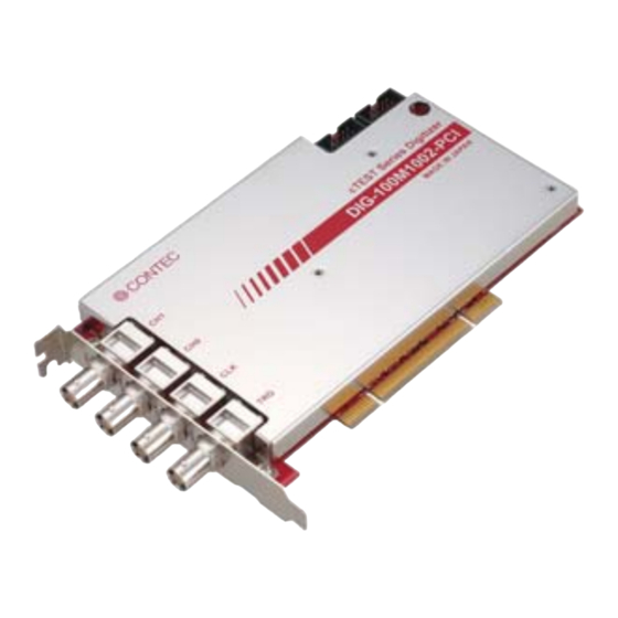
- Page 1 100MSPS 2ch Digitizer Board for PCI DIG-100M1002-PCI User’s Guide CONTEC CO., LTD.
- Page 2 Check Your Package Thank you for purchasing the CONTEC product. The product consists of the items listed below. Check, with the following list, that your package is complete. If you discover damaged or missing items, contact your retailer. Product Configuration List - Board [DIG-100M1002-PCI] …1...
-
Page 3: Copyright
No part of this document may be copied or reproduced in any form by any means without prior written consent of CONTEC CO., LTD. CONTEC CO., LTD. makes no commitment to update or keep current the information contained in this document. The information in this document is subject to change without notice. -
Page 4: Table Of Contents
When Using the API-AIO(WDM) ....................15 Step 4 Checking and Changing the Initialization Setup ..............16 Step 5 Checking Operations with the Front Panel Software ............. 18 What is the front panel software? ....................18 Check Method ..........................18 DIG-100M1002-PCI... - Page 5 The Other Function ........................43 ABOUT SOFTWARE CD-ROM Directory Structure ......................45 About Software for Windows ......................46 When using the API-DIG(WDM) ..................... 47 Accessing the Help File ......................47 Using Sample Programs ......................48 Uninstalling the Driver Libraries ...................... 55 ABOUT HARDWARE DIG-100M1002-PCI...
- Page 6 Hardware specification ........................57 Block Diagram ..........................62 Timing for Control Signal ......................... 63 Timing for Control Signal of Analog Input Function ..............63 DIG-100M1002-PCI...
- Page 7 DIG-100M1002-PCI...
-
Page 8: Before Using The Product
You can use it easily with no need of programming. Moreover, you can use it to check the configured execution environment, because it features the functionality of diagnosing and reporting the status of the board and device driver. DIG-100M1002-PCI... - Page 9 BNC connector used for analog input, trigger and reference clock The BNC connector used for the connector has a characteristic impedance of 50Ω and is of a type commonly used for high speed analog signal. DIG-100M1002-PCI...
- Page 10 The created file can be read by front panel software or from the program using API-PAC(W32) cTEST. Windows compatible driver library API-PAC(W32) cTEST is attached. Using the attached driver library makes it possible to create applications of Window. DIG-100M1002-PCI...
-
Page 11: Support Software
For more details on the supported OS, applicable language and new information, please visit the CONTEC’s Web site. Cable & Connector (Option) < For analog I/O >... -
Page 12: Customer Support
You can download updated driver software and differential files as well as sample programs available in several languages. Note! For product information Contact your retailer if you have any technical question about a CONTEC product or need its price, delivery time, or estimate information. Limited Three-Years Warranty CONTEC products are warranted by CONTEC CO., LTD. -
Page 13: Safety Precautions
Otherwise, this product may malfunction, overheat, or cause a failure. Be sure that the personal computer power is turned off. Do not touch the external connector (BNC connector) when the power is on. Otherwise this may malfunction, cause a failure due to static electricity. DIG-100M1002-PCI... - Page 14 Even when using the product continuously, be sure to read the manual and understand the contents. Do not modify the product. CONTEC will bear no responsibility for any problems, etc., resulting from modifying this product. Regardless of the foregoing statements, CONTEC is not liable for any damages whatsoever (including damages for loss of business profits) arising out of the use or inability to use this CONTEC product or the information contained herein.
-
Page 15: Environment
(3) Store the package at room temperature at a place free from direct sunlight, moisture, shock, vibration, magnetism, and static electricity. Disposal When disposing of the product, follow the disposal procedures stipulated under the relevant laws and municipal ordinances. DIG-100M1002-PCI... -
Page 16: Setup
Step 3 Installing the Hardware Step 4 Checking and Changing the Initialization Setup Step 5 Checking Operations with the front panel software If Setup fails to be performed normally, see the “Setup Troubleshooting” section at the end of this chapter. DIG-100M1002-PCI... -
Page 17: Step 1 Installing The Software
If the panel does not appear, run (CD-ROM drive letter):\AUTORUN.exe. (3) Click on the [Install Development or Execution Environment] button. CAUTION Before installing the software in Windows 7, Vista, XP, Server 2003, or 2000, log in as a user with administrator privileges. DIG-100M1002-PCI... - Page 18 (2) Select the "Digitizer driver". (3) Click on the [Install] button. Run the installation (1) Complete the installation by following the instructions on the screen. (2) The Readme file appears when the installation is complete. You have now finished installing the software. DIG-100M1002-PCI...
-
Page 19: Step 2 Setting The Hardware
Note that the switches and jumpers setting shown below is the factory default. Synchronization control cable (CN6, CN7) Board ID Setting Switch BOARD ID cTEST Series Digitizer DIG-100M1002-PCI MADE IN JAPAN Interface connector (CH0, CH1, CLK, TRG) Figure 2.1. Part Names DIG-100M1002-PCI... -
Page 20: Setting The Board Id
To set the board ID, use the rotary switch on the board. Turn the SW1 knob to set the board ID as shown below. BOARD ID Factory setting : (Board ID = 0) Figure 2.2. Board ID Settings (SW1) DIG-100M1002-PCI... -
Page 21: Plugging The Board
If +5V is not supplied from the PCI bus slot, board is not recognized from PC (”Found New Hardware Wizard” in the next page is not displayed.). In this case, change the expansion slot to be attached or PC to be installed. DIG-100M1002-PCI... -
Page 22: Step 3 Installing The Hardware
[Recommended]" and then click the "Next" button. The wizard may not appear for some OS versions and instead the installation will start automatically. In this case, proceed to the software initial setup step. You have now finished installing the hardware. DIG-100M1002-PCI... -
Page 23: Step 4 Checking And Changing The Initialization Setup
- DIG-100M1002-PCI (2) Hardware that was installed is registered under the CONTEC Devices tree. When you open the devices tree, hardware name that was installed is displayed. The character string of “DIG000” displayed in the right side of hardware name is the device name. - Page 24 (1) Double click the device on the device manager to display the property page of device. Enter the device name in the common settings tab page and then click [OK]. Make sure that you do not use the same name for more than one device. You have now finished installing the initial setting of Software. DIG-100M1002-PCI...
-
Page 25: Step 5 Checking Operations With The Front Panel Software
Chapter 3 “External Connection”. CAUTION Input data remains indeterminate when no input pin is connected. The input pin for the channel not connected to the signal source must be connected to the analog ground. For details, see Chapter 3 “External Connection”. DIG-100M1002-PCI... -
Page 26: Operating The Front Panel Software
Click the [Front Panel] button on the device property page to start the front panel. Pressing the [Auto Setup] button automatically detects the signal of channel and adjusts the screen display. For more details on the using method of front panel software, refer to the API-DIG(WDM) HELP. DIG-100M1002-PCI... - Page 27 Click [Diagnosis Report] and then specify the folder to save the diagnosis report (text file). (2) The diagnosis report contains the following data. Version of OS Device Information (Device Name, Device description) File Information (file version, time stamp) Initialization, interrupts, current input or output state for each channel DIG-100M1002-PCI...
-
Page 28: Setup Troubleshooting
Check the return values of the API functions. Refer to the source code for the sample programs. The OS won’t normally get started or detect the device. Refer to the "Troubleshooting" section of API-DIG(WDM) HELP. If your problem cannot be resolved Contact your retailer. DIG-100M1002-PCI... - Page 29 2. Setup DIG-100M1002-PCI...
-
Page 30: External Connection
- BNC connector [plug type] B6252HB-NPP3G-50 cTEST Series Digitizer [mfd. by AMPHENOL TAIWAN] DIG-100M1002-PCI or equivalence to it MADE IN JAPAN (CH0, CH1, CLK, TRG) * Please refer to chapter 1 for more information on the supported cable and accessories. -
Page 31: Connector Pin Assignment
Digital Ground Digital ground common to digital I/O signals. Figure 3.3. Pin Assignment of CH0, CH1, CLK, TRG CAUTION Please do not connect the analog ground and the digital ground. The measurement result of the analog signal may be influenced. DIG-100M1002-PCI... -
Page 32: Connecting The Analog Input Signal
Please adjust the input impedance to 50Ω when the signal reflection etc. are anxious. However, the effect cannot be achieved except for cases such as setting the output impedance of the signal source to 50Ω, and setting the characteristic impedance of the used connector/cable etc. to 50Ω. DIG-100M1002-PCI... -
Page 33: Connecting The External Trigger I/O Signal
Doing either can cause a malfunction. The signal input of 5VTTL/5VCOMOS is possible. The input is the default at startup. Reference For the operation timings for trigger I/O signal, see “Timing for Control Signal” in Chapter 6 “About Hardware”. DIG-100M1002-PCI... -
Page 34: Connecting The Reference Clock I/O Signal
Digital Ground Figure 3.8. Connecting the Reference Clock Output CAUTION Do not connect any output signal to the analog or digital ground. Do not interconnect outputs. Doing either can cause a malfunction. The input is the default at startup. DIG-100M1002-PCI... - Page 35 CLK can be selected besides the reference clock from outside. Output Connector Output circuit PLL circuit Oscillator Figure 3.9. Connecting the Reference Clock Reference For the input / output condition of reference clock, see “Reference Clock I/O” in Chapter 6 “About Hardware”. DIG-100M1002-PCI...
-
Page 36: Synchronization Control Connectors
CAUTION When sampling clock signals are assigned to the synchronization control connector, the maximum clock frequency is restricted to 5MHz. When signals are assigned to the synchronization control connector, a delay of approximately 100nsec occurs at the slave board. DIG-100M1002-PCI... -
Page 37: Connecting The Sc Connectors (Cn6, Cn7)
Connect CN6 with a smaller ID number to CN7 with a greater ID number with the cable. You should only use the cable that came with the board. ID = 0 ID = 1 ID = 2 Figure 3.10. Connecting Cables DIG-100M1002-PCI... -
Page 38: Functions
Moveover, the data is acquired periodically avoiding the overflow of driver memory, by which infinite sampling can be performed. The figure is a data acquisition image in the data logger mode. In data logger mode, it is possible to control data acquisition timing with two kinds of triggers, pre- trigger and post-trigger. DIG-100M1002-PCI... -
Page 39: Waveform Judgment Instrument Mode
The figure is a data acquisition image in the waveform judgment instrument mode. The record loss is inhibited. The digitizer operation stops when all records cannot be acquired by exceeding the limit of the processing performance. DIG-100M1002-PCI... -
Page 40: Overviews Of Setting Order
Start the digitizer operation after setting acquisition conditions. It is possible to generate a signal and stop the operation by a software command. The state of the digitizer can be confirmed by acquiring the status, the number of samples, the number of records etc. DIG-100M1002-PCI... -
Page 41: Common Setting
For example, to detect the operation completion of the digitizer in the application, if the event notification function is used, the specified handler in the program is called when the digitizer operation completed, though the program is made to observe states such as the status and the number of samples usually. DIG-100M1002-PCI... -
Page 42: Horizontal Axis Setting
The horizontal axis setting becomes the common setting contents for plural channels. Reference clock CONTEC digitizer uses LVTTL signal of 10MHz, duty ratio of 50% as a reference clock. The reference clock of 10MHz is a frequency that can be used by most measuring instruments. - Page 43 When the digitizer is used in the oscilloscope mode, the latest acquisition data is transferred after waiting for the on-board memory to ensure space. Therefore, the loss should occur to the acquired waveform though the operation of the digitizer never stops. DIG-100M1002-PCI...
-
Page 44: Vertical Axis Setting
This product has the following ten kinds of ranges, the waveform of the analog signal can be digitalized by selecting an appropriate input range according to the voltage range of the input signal. The input range is mainly described in a full scale range for CONTEC digitizer. Input range Full-scale range (FSR) ±20V... - Page 45 The resistance of the signal input circuit (digitizer board) is called an input impedance. The input impedance can be set to 50Ω or 1MΩ for CONTEC digitizer board. The current flows to the digitizer when the input impedance of the digitizer is low, and the measurement result is influenced by the voltage descent.
-
Page 46: Trigger Setting
10V and an offset of 0V. By doing so, data before and after the generation of this trigger are respectively digitized as pre-trigger sample and post-trigger sample, and plural record waves consist of sample data with the same shape. DIG-100M1002-PCI... - Page 47 It is the trigger occurs at the rising edge or the falling edge of external digital input signal, and the signal level is LVTTL. It is possible to input a trigger from other CONTEC board via the synchronization control connector (CN6, CN7).
-
Page 48: Waveform Judgment Setting
When synchronization start is used, the driver function doesn't return the control until the the digitizer stopped operating. Therefore, the application cannot do other processing until the digitizer stopped operating. On the other hand, the programming becomes concise for there’s no need to detect the operation completion of the digitizer. DIG-100M1002-PCI... -
Page 49: Status / Data Acquisition
The overview data of the waveform judgment result contains the state of OK or NG for the judgment result of the record. The detailed data of the waveform judgment result contains the information that each sample data of the record whether exceeds the upper bound/lower bound value of the mask data, or is within the range. DIG-100M1002-PCI... -
Page 50: The Other Function
The signal of synchronization bus is output to Trigger Output. A pulse is output to synchronization bus or Trigger Output when the digitizer stops abnormally. Master device or slave device is aborted by conditions such as an error that occurred in the board. DIG-100M1002-PCI... - Page 51 4. Functions DIG-100M1002-PCI...
-
Page 52: About Software
Version information on each driver (English) |–––APIPAC Each installer |––AioWdm |––CntWdm |––DigWdm |––…… | ––INF INF file for each driver |––WDM |––Aio |––Cnt |––Dig |––……. | ––Readme Readme file for each driver | ––UsersGuide Hardware User's Guide (PDF files) DIG-100M1002-PCI... -
Page 53: About Software For Windows
Acquisition conditions can be set to the device in mass with a configuration file. For details, refer to the help file. The help file provides various items of information such as “Function Reference”, “Sample Programs”, and “FAQs”. Use them for program development and troubleshooting. DIG-100M1002-PCI... -
Page 54: When Using The Api-Dig(Wdm)
5. About Software When using the API-DIG(WDM) Accessing the Help File (1) Click on the [Start] button on the Windows taskbar. (2) From the Start Menu, select “Programs” – “CONTEC API-PAC(W32)” – “API-DIG(WDM)” – “API-DIG(WDM) HELP” to display help information. DIG-100M1002-PCI... -
Page 55: Using Sample Programs
The sample programs are stored in \Program Files\CONTEC\API-PAC(W32)\DIGWDM\Samples. Running a Sample Program (1) Click on the [Start] button on the Windows taskbar. (2) From the Start Menu, select “Programs” - “CONTEC API-PAC(W32)” - “API-DIG(WDM)” - “SAMPLE…”. (3) A sample program is invoked. - Page 56 OschilloScope Mode - OschilloScope Sampling using auto setup function - LoadConfig Sampling for plural channels using configuration file Waveform judgment mode - WaveformJudgement1 Waveform judgment using auto mask function - WaveformJudgement2 Waveform judgment using fixed value for judgment standard DIG-100M1002-PCI...
- Page 57 By using the configuration file, there’s a merit that the amount of program source code is decreased, and the measurement parameters can be changed without changing the source code itself. Click “Configuration Wizard” from “Start” menu-“Program”-“CONTEC API-PAC(W32)”-“API- DIG(WDM)” to use the configuration software.
- Page 58 (3) Specify the path to save the file on the last page. Then the configuration file is created in the specified path when the “Finish” button is clicked. Complete the operation without creating a configuration file by clicking the “Cancel” button. DIG-100M1002-PCI...
- Page 59 The mask data for the waveform judgment can be intuitively created by using the mask editor software. Moreover, the judgment data can be theoretically created for that the waveform can be generated with a mathematics function. Click “Mack Editor” from “Start” menu-“Program”-“CONTEC API-PAC(W32)”-“API-DIG(WDM)” to use the mask editor software. *The name of the board you have just added is displayed.
- Page 60 - Horizontal axis setting - Vertical axis setting - Trigger setting - Waveform judgment setting The display is grayout when the setting cannot be done by the combination. For more details on the setting contents, refer to “API-DIG(WDM) HELP”. DIG-100M1002-PCI...
- Page 61 Moreover, you may confirm the value of set data or edit the data value directly on the [Data Viewer] window.20090527 (4) Choose “File…”-“Save As…” from the menu and specify the saving path of the file to save the mask data edited. DIG-100M1002-PCI...
-
Page 62: Uninstalling The Driver Libraries
[Device Manager] tab. (You can also open Device Manager by right clicking on My Computer and selecting Properties.) 2. All of the hardware that uses the API-TOOL(WDM) driver is registered under the CONTEC Devices tree. Open the device tree, select the hardware to uninstall, and then right-click the hardware. - Page 63 < Uninstall the device driver > Use [My Computer] - [Control Panel] - [Add and Remove Programs] to uninstall the device driver. Select [Windows driver package - CONTEC (****)] and then click [Change/Remove]. < Uninstall the development environment > Use [My Computer] - [Control Panel] - [Add and Remove Programs] to uninstall the development environment.
-
Page 64: About Hardware
*1 : Switch to 1MΩ automatically when power is turned off. *2 : Do not input a voltage over the Max. input voltage. It may cause failure. *3 : When 2ch are used, the Max. conversion speed is 50MHz (when data logger mode is used.). DIG-100M1002-PCI... - Page 65 *4 : The designated precision may not be satisfied because of cable. *5 : Voltage generator R6161 [ADVANTEST] is used in measurement. *6 : It is the value when offset/range is set to 0V. *7 : It is the value when noise filter is set to off. DIG-100M1002-PCI...
- Page 66 Noise filtering is OFF. Noise filtering is ON. Amplitude- frequency property (typ) Input signal : 10MHz, -1dBFS Number of sampling channel : 131072 Noise filtering : OFF -100 0.05 0.15 0.25 0.35 0.45 Frequency(100MHz) Spectrum property (typ) : 50Ω, 1Vpk range DIG-100M1002-PCI...
- Page 67 BNC (Characteristic Impedance 50Ω) Currrent consumption 5VDC 1.9A (Max.), 3.3VDC 0.1A (Max.) Operating condition 0 - 50°C, 10 - 90%RH (No condensation) Bus specification PCI (32bit, 33MHz, Universal key shapes supported *9) Dimensions (mm) 176.41(L) x 105.68(H) Weight 400g DIG-100M1002-PCI...
- Page 68 *9 : This product requires +5V and +3.3V power supply from expansion slots. Board Dimensions 176.41(L) [mm] The standard outside dimension (L) is the distance from the end of the board to the outer surface of the slot cover. DIG-100M1002-PCI...
-
Page 69: Block Diagram
AC / DC / GND Noise Filter Noise Filter Oscillator ON / OFF ON / OFF To Other Board SyncBUS Timing GAIN GAIN Connector OFFSET OFFSET Controller AD Converter AD Converter Controller Memory PCI BUS Figure 6.1. Block Diagram DIG-100M1002-PCI... -
Page 70: Timing For Control Signal
Timing for Control Signal of Analog Input Function DIG-100M1002-PCI is unrelated with the sampling clock, it is always sampled in each 10nsec. In a word, the conversion results from the A/D convertor are stored in an internal register once, the values are updated in each 10nsec. - Page 71 When digital filter is being used, the delay time is added by 50ns. *2 1nsec is 1/1,000,000,000 seconds. *3 The internal clock less than 100nsec cannot be output. And it is always maintained to “H”at 100nsec. CAUTION All the model values are shown at the time of Table 6.2. DIG-100M1002-PCI...
- Page 73 CONTEC CO., LTD. June 2018 Edition 3-9-31, Himesato, Nishiyodogawa-ku, Osaka 555-0025, Japan https//www.contec.com/ No part of this document may be copied or reproduced in any form by any means without prior written consent of CONTEC CO., LTD. [06042018] [12112009] Management No. NA00059 [06042018_rev4] Parts No.