
Related Manuals for BKI DRG-40


Summary of Contents for BKI DRG-40
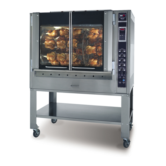
- Page 1 Gas Rotisserie Oven MODEL DRG-40 Installation and Operation Manual Serial Numbers 120170 and Higher...
-
Page 2: Warranty Information
Warranty Information LIMITED ONE YEAR WARRANTY BKI (The "Company") warrants to the original purchaser that at time of shipment from the Company factory, this equipment will be free from defect in materials and workmanship. Written notice of a claim under this warranty must be received by the Company within ONE YEAR from the date of installation, but no longer than ONE YEAR AND THREE MONTHS from date of shipment from the factory. -
Page 3: Table Of Contents
Inspection for Shipping Damage ... 14 Preparation... 14 Location and Clearance ... 15 Installation Procedure... 15 Gas Conversion Instructions ... 16 Maintenance ... 17 Scheduled Maintenance... 17 Oven Cleaning ... 17 Troubleshooting... 24 Appendix A... 25 Table of Contents Table of Contents... -
Page 4: Introduction
Gas Rotisserie Oven Your DRG-40 is a computer controlled gas fired rotisserie oven. It utilizes a double revolving rotor system to ensure even product cooking. The unit contains a single stage cook and hold computer with 5 customizable cook programs. Electrical controls are provided for powering the unit, turning on inside lights, igniting upper/lower burners, turning the rotors, filling the water bath and resetting the unit. -
Page 5: Safe Work Practices
If you lose or damage your mitts, you can buy new ones at your local restaurant equipment supply store or from your local BKI Distributor. Always wear non-skid shoes when working around the oven or any other equipment. Never wear loose clothing such as neckties or scarves while operating this equipment. - Page 6 Before using this appliance for the first time, contact your local gas supplier for instructions about what to do if you smell gas. Post those instructions somewhere near the oven, so that everyone who uses or works near the oven knows what to do if they smell gas.
- Page 7 Gas Rotisserie Oven Introduction Do Not Smoke Near The Oven This oven uses combustible fuels to operate. Smoking near this oven could possibly cause a fire. Do not allow anyone to smoke near this oven.
-
Page 8: Safety Labels
Gas Rotisserie Oven Introduction Safety Labels... - Page 9 Gas Rotisserie Oven Introduction...
-
Page 10: Operation
Gas Rotisserie Oven Operation Operation Controls and Indicators Refer to the figure and table below for an explanation of the oven’s controls and indicators. - Page 11 Controls power to the entire unit. Controls ignition of top burners if ROTOR and POWER switch are on and doors are shut. Controls power to the lights inside oven. Controls power to the motor that turns the rotors if the POWER switch is on.
-
Page 12: Controller Operation
Gas Rotisserie Oven Operation Controller Operation The DRG-40 contains a single-stage cook and hold timer/temperature controller that has 5 cook programs and 5 modes of operation. This section explains the operating modes and programming of the controller. Modes Ready Mode This mode is used to inform the operator that the oven temperature is at the initial temperature (Ready Range) for a particular program. -
Page 13: Programming
The controller may also operate with the cook and/or hold temperature set to “OFF”. When both the cook and hold temperature are set to “OFF”, the controller will not regulate the oven temperature. This feature is intended for demonstration or display purposes. -
Page 14: Cooking
All burners are turned “OFF” when the doors are opened. Always allow a minimum of three (3) seconds before closing the doors again. 5. Open the oven doors and load the product. Use the ROTOR JOG switch on the front panel to operate the rotors during loading. -
Page 15: Probe (Thermocouple) Diagnostics
“PROB”. Operation After Gas or Power Outage The oven will shut off automatically if the gas supply is interrupted or the power goes out. If either of these conditions occur you should perform the following procedure: For your safety, if the gas supply stops, or, if the power goes out, make sure to wait for at least five minutes before restarting your oven. -
Page 16: Installation
½ psi (3.5 kPa). The oven must be isolated from the gas supply piping system by closing its individual manual shutoff valve during any pressure testing of the gas supply piping system at test pressures equal to or less than ½... -
Page 17: Location And Clearance
• The drain on the DRG-40 is a ¾” ball valve. Under NO circumstances, should this valve be hard plumbed to a drain line. A short nipple may be used to direct the discharge into a 2” drain that should have a bell reducer (to act as a funnel) placed on the end of drain line. -
Page 18: Gas Conversion Instructions
5. Turn on the gas at the gas supply valve. 6. Check for gas leaks from the gas supply to the oven gas valve using a soap and water solution. If a leak is detected, tighten the connection where the leak occurs. -
Page 19: Maintenance
Using abrasive cleaners may damage the cabinet finish. Use only a mild soap and water solution. DO NOT USE OVEN CLEANER on this machine. Caustic cleaners can cause damage to the machine. NEVER USE A WATER HOSE OR A STEAM CLEANER TO WASH THIS UNIT. - Page 20 Gas Rotisserie Oven 2. Turn off all switches and controls and let the oven cool. 3. Drain and dispose of the renderings from bottom of oven. 4. Remove all food products from the unit. Remove V-spits, meat baskets and meat forks from the unit and place them in a large sink to soak in hot cleaning solution (BKI Cleaner).
- Page 21 Gas Rotisserie Oven Maintenance • Place the rotor shaft in a large sink.
- Page 22 Gas Rotisserie Oven • If using a dual rotor shaft, loosen the center spinner hub. CENTER SPINNER Remove the center rotor from the shaft and place in large sink. Maintenance...
- Page 23 Gas Rotisserie Oven • Pull drive rotor away from the oven wall to disengage drive hub (on rotor) from the drive shaft and place in sink. Maintenance...
- Page 24 Gas Rotisserie Oven • Pull passive rotor away from the oven wall to disengage drive hub (on rotor) from the drive shaft and place in sink. Maintenance...
- Page 25 BKI Cleaner. Wipe dry with a clean cloth. 7. Clean the outside and inside of the rotisserie oven with warm water, a sponge and an approved cleaner which is authorized for use on food surface areas.
-
Page 26: Troubleshooting
Light switch may not be on. Controller displays “PROB”. Thermocouple connection is loose or thermocouple defective. Water Fill is not working Water supply to oven may be off. Defective oven water system. Possible Solution Check circuit breaker or fuses at building power panel. -
Page 27: Appendix A
Gas Rotisserie Oven Appendix A Appendix A Gas Control Valve Instructions... - Page 28 APPLICATION These direct ignition gas controls are used in gas-fired appliances with up to 415 ft /hr. capacity at 1 in. wc pressure drop (8.5 m /hr at 0.25 kPa) on natural gas. They include a manual valve, two automatic operators and a pressure regulator.
-
Page 29: Specifications
VR8105, VR8205, AND VR8305 DIRECT IGNITION COMBINATION GAS CONTROLS SPECIFICATIONS Body Pattern: Straight through; see Table 1 for inlet and outlet size. Electrical Ratings: Voltage and Frequency: 24 Vac, 60 Hz. Current Draw: 0.5A with both operators energized. Capacity: See Table 1. Conversion: Use conversion factors in Table 2 to convert capacities for other gases. - Page 30 VR8105, VR8205, AND VR8305 DIRECT IGNITION COMBINATION GAS CONTROLS Table 6 shows additional specifications for the CE-only models. Specification Main Valve Connection Ambient Temperature Range Maximum Inlet Pressure Pressure Regulation Regulator Adjustment Ground Terminal Pressure Taps Valve Classification CAUTION Equipment Damage Hazard. Improper use can damage equipment.
- Page 31 VR8105, VR8205, AND VR8305 DIRECT IGNITION COMBINATION GAS CONTROLS CAUTION Equipment Damage. Can burn out valve coil terminals. Never apply a jumper across (or short) the valve coil terminals, even temporarily. Follow the appliance manufacturers instructions if available; otherwise use these instructions as a guide. IMPORTANT These gas controls are shipped with protective seals over the inlet and outlet tappings.
- Page 32 VR8105, VR8205, AND VR8305 DIRECT IGNITION COMBINATION GAS CONTROLS Complete the instructions below for installing the piping, installing the control, connecting the pilot gas tubing and the wiring. Make sure the leak test you perform on the control after completing the installation includes leak testing the adapters and screws.
- Page 33 VR8105, VR8205, AND VR8305 DIRECT IGNITION COMBINATION GAS CONTROLS WHEN FLANGE IS NOT USED APPLY WRENCH FROM TOP OR BOTTOM OF GAS CONTROL TO EITHER SHADED AREA Fig. 5. Proper use of wrench on gas control with and without flanges. HI-LO ADJUSTMENT SCREWS (UNDER CAP)
- Page 34 VR8105, VR8205, AND VR8305 DIRECT IGNITION COMBINATION GAS CONTROLS S87 CONTROL MODULE ALARM 24V (GND) VALVE VALVE IGNITER-SENSOR AND BURNER GROUND TEMPERATURE CONTROLLER POWER SUPPLY. PROVIDE DISCONNECT MEANS AND OVERLOAD PROTECTION AS REQUIRED. ALTERNATE LIMIT CONTROLLER LOCATION. MAXIMUM IGNITER-SENSOR CABLE LENGTH: 3 ft. [.9 m] OR LESS. 3 A REPLACEABLE FUSE.
- Page 35 VR8105, VR8205, AND VR8305 DIRECT IGNITION COMBINATION GAS CONTROLS Check and Adjust Gas Input and Burner Ignition IMPORTANT 1. Do not exceed input rating stamped on appliance nameplate, or manufacturer’s recommended burner orifice pressure for size orifice(s) used. Make certain primary air supply to main burner is properly adjusted for complete combustion.
- Page 36 VR8105, VR8205, AND VR8305 DIRECT IGNITION COMBINATION GAS CONTROLS 4. With main burner operating, check the gas control flow rate using the meter clocking method or check pressure using a manometer connected to the outlet pressure tap on the gas control. See Fig. 6. 5.
- Page 37 VR8105, VR8205, AND VR8305 DIRECT IGNITION COMBINATION GAS CONTROLS Table 9. Pressure Regulator Specification Pressures (kPa). Type of Nominal Inlet Model Type Pressure Range Standard, 1.2-1.7 Slow 2.9-3.9 Step 1.2-1.7 2.9-3.9 Two-stage 1.2-1.7 2.9-3.9 Low Fire setting range for VR8305Q 1/2 in. by 1/2 in. and 1/2 in. by 3/4 in. is 0.37 to 0.75 kPa. Check Safety Shutdown Performance WARNING Fire or Explosion Hazard.
- Page 38 VR8105, VR8205, AND VR8305 DIRECT IGNITION COMBINATION GAS CONTROLS CAUTION Equipment Damage. Can burn out valve coil terminals. Never apply a jumper across (or short) the valve coil terminals, even temporarily. After servicing, verify proper system operation. If Main Burner Does Not Come On With Call For Heat 1.
- Page 39 Automation and Control Solutions Honeywell International Inc. Honeywell Limited-Honeywell Limitée 1985 Douglas Drive North 35 Dynamic Drive Golden Valley, MN 55422 Scarborough, Ontario M1V 4Z9 69-1226—2 G.R. Rev. 11-99 Printed in U.S.A. on recycled paper containing at least 10% post-consumer paper fibers. www.honeywell.com...
- Page 40 P.O. Box 80400, Simpsonville, S.C. 29680-0400, USA http://www.bkideas.com Made and printed in the U.S.A LI0175/0807...