Furuno FE-700 Installation Manual
Navigational echo sounder
Hide thumbs
Also See for FE-700:
- Installation manual (61 pages) ,
- Service manual (58 pages) ,
- Operator's manual (44 pages)
Table of Contents
Advertisement
Quick Links
Installation Manual
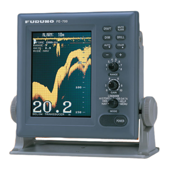
NAVIGATIONAL ECHO SOUNDER
FE-700
Model
SAFETY INSTRUCTIONS ................................................................................................ i
SYSTEM CONFIGURATION ........................................................................................... ii
EQUIPMENT LISTS........................................................................................................ iii
1. MOUNTING................................................................................................................. 1
1.1 Category of Equipment .........................................................................................................1
1.2 Display Unit...........................................................................................................................1
1.3 Transducer............................................................................................................................4
1.4 Distribution Box.....................................................................................................................6
1.5 Matching Box ........................................................................................................................7
1.6 Digital Depth Indicator FE-720 (option).................................................................................7
1.7 Transducer Switch Box EX-8 (option)...................................................................................9
1.8 Gate Valve GV-50B-6B, GV-200B-8B (option) .....................................................................9
2. WIRING..................................................................................................................... 11
2.1 Wiring..................................................................................................................................11
2.2 Cable Fabrication................................................................................................................13
2.3 Transducer..........................................................................................................................17
2.4 Ground ................................................................................................................................17
2.5 Alarm system connection....................................................................................................17
2.6 Digital Depth Indicator FE-720............................................................................................18
3. CHANGING POWER SPECIFICATIONS................................................................. 19
4. ADJUSTMENTS ....................................................................................................... 21
4.1 Transducer Setting..............................................................................................................21
4.2 Setting the Time..................................................................................................................23
PACKING LISTS ......................................................................................................... A-1
OUTLINE DRAWINGS ................................................................................................ D-1
INTERCONNECTION DIAGRAMS.............................................................................. S-1
www.furuno.com
All brand and product names are trademarks, registered trademarks or service marks of their respective holders.
Advertisement
Table of Contents

Related Manuals for Furuno FE-700


Summary of Contents for Furuno FE-700
-
Page 1: Table Of Contents
Installation Manual NAVIGATIONAL ECHO SOUNDER FE-700 Model SAFETY INSTRUCTIONS ....................i SYSTEM CONFIGURATION ................... ii EQUIPMENT LISTS......................iii 1. MOUNTING......................... 1 1.1 Category of Equipment ......................1 1.2 Display Unit...........................1 1.3 Transducer..........................4 1.4 Distribution Box........................6 1.5 Matching Box ........................7 1.6 Digital Depth Indicator FE-720 (option).................7 1.7 Transducer Switch Box EX-8 (option)...................9... - Page 2 ・FURUNO Authorized Distributor/Dealer 9-52 Ashihara-cho, Nishinomiya, 662-8580, JAPAN A : JAN 2000 Printed in Japan All rights reserved. U : SEP . 01, 2020 Pub. No. IME-23660-U (TAYA ) FE-700 0 0 0 8 0 8 9 1 0 1 5...
-
Page 3: Safety Instructions
When handling the transducer cable, proper installation of the equipment. keep in mind following points: FURUNO will assume no responsibility for any damage associated with improper - Keep the cable away from oil and fuel. installation. -
Page 4: System Configuration
SYSTEM CONFIGURATION DISPLAY UNIT FE-701 Terminal Box DS-802 IEC 61162-1 DIGITAL DEPTH INDICATOR FE-720 IEC 61162-1 Navigation Device DISTRIBUTION IEC 61162-1 BOX FE-702 Navigation Device EIA-232C Personal Computer Contact signal Alarm Unit AU-12 100/110-115/ 200/220-230 VAC DC24 V DISTRIBUTION SWITCH BOX EX-8 MB-1200 JUNCTION BOX... -
Page 5: Equipment Lists
EQUIPMENT LISTS Standard Supply Name Type Code No. Remarks Display Unit FE-701 — w/Installation Materials CP02- 06400 (000-015-872) and Ac- cessories FP02-04800 (000- 015-469) Distribution Box FE-702 — Matching Box MB-502 000-013-602 For 50B-6B MB-504 000-013-604 For 200B-8B Transducer 50B-6B —... - Page 6 EQUIPMENT LISTS Name Type Code No. Remarks Data Recording 02-522-990 001-229-090 For Windows 95/98/NT4.0 Software for PC Digital Depth Indica- FE-720 000-029-025 1 set w/Installation Materials CP02-06700 (000-029- 068)Spare Parts SP65- 00601 (002-889-730)Acces- sories FP65-00400 (000- 029-067) Dimmer MF-22L-1-100V 000-069-401 100 VAC-120 VAC, Flush mount type MF-22L-1-200V...
-
Page 7: Mounting
MOUNTING NOTICE Do not apply paint, anti-corrosive sealant or contact spray to coating or plastic parts of the equipment. Those items contain organic solvents that can damage coating and plastic parts, especially plastic connectors. Category of Equipment Equipment for protected area •... - Page 8 1. MOUNTING • A magnetic compass will be affected if placed too close to the display unit. Observe the following compass safe distances to prevent disturbance to the magnetic com- pass. Standard compass: 0.55 meters Steering compass: 0.35 meters Cover Desktop Overhead 1.2.2...
- Page 9 1. MOUNTING 3. Attach the dummy covers to the unused holes. Dummy cover 5x20 tapping screws 1.2.4 Flush mounting There are two types of flush mount kits, F type and S type. For details, see the outline diagrams at the back of this manual.
-
Page 10: Transducer
1. MOUNTING F type Flush Mount Kit (F): OP02-79-1 (001-229-290) OP02-79-2 (001-229-300) OP02-79-3 (001-229-310) Name Type Code no. Remarks Cosmetic 02-129-1041-0 100-279-270 OP02-79-1:N3.0 panel 100-279-280 OP02-79-2:2.5GY5/1.5 100-279-290 OP02-79-3:7.5GY7/2 Hex bolt M6x12 000-162-897-10 Spring 000-158-855-10 washer 1. Prepare a cutout in the mounting location whose dimensions are 210 (W) x 194 (H) mm. - Page 11 1. MOUNTING 1.3.1 Mounting Location To decide the location of the transducer, the following points should be taken into ac- count. • The most important matter is where the transducer is installed. The position should be free from aeration possibly occurring beneath the hull and also not affected by engine and propeller noise.
-
Page 12: Distribution Box
1. MOUNTING the junction box (or matching box). This will protect the transducer from vibration and damage. SGP 1 /4" 1 Transducer (50B-6B) JIS B2221 5 -32 2 Transducer Tank 4- 15 FIXING HOLE 3 Fixing Flange 4 Gland Nut 5 Washer 6 Rubber Gasket 7 Hex. -
Page 13: Matching Box
1. MOUNTING Matching Box The matching box should be selected depending on the transducer type; • 50B-6B transducer: MB-502 • 200B-8B transducer: MB-504 Fasten the matching box with four Trapping screws (6x20: local supply). Compass safe distances are as follows; standard compass: 0.50 m, Steering compass: 0.40 m. Digital Depth Indicator FE-720 (option) The indicator can be installed on a tabletop, on the overhead. - Page 14 1. MOUNTING F type Use the accessories FP65-00401 (See page A-7). 1. Prepare a cutout in the mounting location whose dimensions are 183 (W) x 92 (H) 2. Attach the cosmetic panel (20-016-1051) to the indicator with two hex bolts (M6x12) and two spring washers (M6).
-
Page 15: Transducer Switch Box Ex-8 (Option)
1. MOUNTING Transducer Switch Box EX-8 (option) If two transducers are installed, the transducers switch box is required. Locate the transducer switch box near the display unit considering length of the interconnection cable. Select the bright place where the panel of equipment can be watched. Use only the screws supplied on the terminal inside to make connections. - Page 16 1. MOUNTING 6. Fix stud bolts with washers and bolts loosely. 7. Keep seachest cap and shaft assembly free of dirt and dust. 8. Grease (supplied) both sides of the gasket 2 and place it onto the gate valve. 9. Place seachest cap and shaft assembly onto the gasket 2. 10.
-
Page 17: Wiring
WIRING Wiring Connect three cable assemblies (supplied) between the display unit and distribution box. See the interconnection diagram for details. Display unit FE-701 (rear panel) FM-C6FPS002-100 MJ-A3SPF0015-100C POWER Digital depth indicator FE-720 (option) DATA When silencing the alarm beep, connect 2.0 sq to *2 connector. - Page 18 2. WIRING When the Transducer Switch Box EX-8 or Distribution Box MB-1200 is used, the in- terconnections are as follows. Display unit FE-701 (rear panel) FM-C6FPS003-020 (for EX-8) MJ-A3SPF0015-100C FM-C6FPS004-050 (for MB-1200) POWER Digital depth indicator FE-720 (option) DATA When silencing the alarm beep, connect 2.0 sq to *2 connector.
-
Page 19: Cable Fabrication
2. WIRING Cable Fabrication 2.2.1 DPYCYS-2.5, DPYCYS-1.5, MJ-A3SPF0015-100C , FM- C6FPS0002-100 and TPYCYS-1.5 Fabricate the power and other cables as illustrated below to connect them to the Dis- tribution box. Vinyl Sheath Cores Shield 40mm 50mm Armor 100mm Fold back shield over on vinyl sheath. Vinyl Sheath Cores Shield... - Page 20 2. WIRING Several cables are required to supply at local. In this manual, JIS (Japan Industrial Standard ) cables are specified. Use equipment cables referring to the figures below. Shield Sheath Shield Sheath Armor Armor Core Core S=1.5 mm S=2.5 mm =1.56mm Vinyl sheath =2.01mm...
- Page 21 2. WIRING 2.2.2 TTYCYS-4 TTYCYS is a Japan Industrial Standard (JIS) cable. Use the equipment one. Vinyl Sheath Shield Cores 40mm 50mm Armor 100mm Fold back shield over on vinyl sheath. Vinyl Sheath Shield Taping Armor Vinyl Tape Vinyl Sheath Shield 3 mm Clamp here.
- Page 22 2. WIRING 2 Rotate Shield Special tool for Armor connecting wires, fitted inside the Conductor Vinyl sheath Distribution Box S =0.75 mm Anticorrosive sheath Insert =1.11 mm (Sectional view) Fabrication of cable TTYCYS-4 Terminal Board TB1, TB3 Cross section Power Supply Cable from Ship's Mains If the ship's mains is AC, the power supply cable must be connected to TB5 in the Dis- tribution Box.
-
Page 23: Transducer
2. WIRING Transducer Connect the transducer cable to the distribution box. If necessary, attach the junction box between the distribution box and matching box. Ground Connect the ground wire (2.0 sq.) from both the display unit and distribution box to ship’s ground to prevent interference to the picture. -
Page 24: Digital Depth Indicator Fe-720
2. WIRING Digital Depth Indicator FE-720 There are two methods to connect the digital depth Indicator FE-720. Case 1: Input signal from the main display unit to FE-720 The interconnection is as follows. DIGITAL DEPTH INDICATOR DISTRIBUTION BOX FE-720 FE-702 TERMINAL BOX DS-802(option) MJ-A7SPF0009-020C... -
Page 25: Changing Power Specifications
CHANGING POWER SPECIFICA- TIONS This unit is set at factory to operate from 220-230 VAC ship's mains. For connection to a 100 VAC, 110-115 VAC, 200 VAC or 24 VDC ship's mains, modify the connec- tions in the distribution box as shown below. Note: Tick the appropriate box on the inside of the FE-702 distribution box cover to denote the power use. - Page 26 3. CHANGING POWER SPECIFICATIONS 24 VDC Ship's Mains 1. Remove the cover of the distribution box. 2. Remove P3 connector from J4 on the CONE Board. 3. Reattach P3 connector to J3 on the CONE Board. 4. Connect the power cable to TB6. CONE Board For DC ship's mains For AC ship's mains...
-
Page 27: Adjustments
- key to set option. EX8 or MB-1200 connected to transducer(s) a) [CHANGEOVER] sets how transducer(s) is connected to the FE-700. Select [MANUAL] for single transducer or transducers connected via Switch Box EX- 8. Select [AUTO] for connection via Distribution Box MB-1200. - Page 28 4. ADJUSTMENTS d) [DEPTH (BELOW)] selects the method of depth indication. [TRANSDUCER] for depth indication below the transducer (except DBS mode), or [KEEL] for depth indication below the keel. e) [DISP MODE] sets the function of the MODE switch in case of dual frequen- cies.
-
Page 29: Setting The Time
4. ADJUSTMENTS Setting the Time 1. Open the [SYSTEM MENU 2] referring to the operator’s manual. SYSTEM MENU 2 MENU SELECT TIME ADJUST INTERNAL EXTERNAL MONTH YEAR 2009 ( 2100) HOUR (0 23) MINUTE (0 59) SECOND (0 59) 01 JAN 2009 00:01:06 : To select item - +: To set option... - Page 40 D-3a...
- Page 41 18/Mar/2014 H.MAKI...
- Page 50 D-13 5/Jun/2020 H.MAKI...
- Page 51 D-14 5/Jun/2020 H.MAKI...
- Page 52 D-15 4/Oct/2018 H.MAKI...
- Page 53 D-16 17/May/2018 H.MAKI...
- Page 54 D-17 5/Jun/2020 H.MAKI...
- Page 55 D-18 9/Jun/2020 H.MAKI...
- Page 56 D-19 T.MAtsuguchi Apr.28'06...
- Page 57 D-20 T.Matsuguchi Apr.28'06...
-
Page 58: Interconnection Diagrams
TRANSDUCER 50kHzのときは必ずメニュー設定を変更のこと。 TRANSDUCER TRANSDUCER *6)接続の詳細はFE-720相互結線図を参照のこと。 NOTE *1. SHIPYARD SUPPLY. DRAWN TITLE *2. OPTION. FE-700 T.YAMASAKI 21/Apr/2014 *3. FITTED AT FACTORY. CHECKED 名称 音響測深機 H.MAKI *4. USE A DISTRIBUTION BOX OR A MATCHING BOX WHEN TWO TRANSDUCERS ARE INSTALLED. 21/Apr/2014 *5. TRANSMIT FREQUENCY IS SET TO 200 kHz AT FACTORY.