Furuno FE-700 Service Manual
Hide thumbs
Also See for FE-700:
- Installation manual (61 pages) ,
- Service manual (58 pages) ,
- Operator's manual (44 pages)

Related Manuals for Furuno FE-700


Summary of Contents for Furuno FE-700
- Page 1 ECHO SOUNDER FE-700 MODEL Downloaded from www.Manualslib.com manuals search engine...
- Page 2 Y o u r L o c a l A g e n t / D e a l e r 9 - 5 2 , A s h i h a r a - c h o , N i s h i n o m i y a , J a p a n T e l e p h o n e : 0 7 9 8 - 6 5 - 2 1 1 1 T e l e f a x :...
- Page 3 Copy these files to a floppy disk to execute the program from the floppy disk. Connect the DATA port on the FE-700 display unit to the serial I/O port of the Turn on the PC. Do not as yet turn on the FE-700.
- Page 4 The PC screen shows the progresses of updating. When loading of new software is completed, “Finish version up.ted” appears on the PC screen while the FE-700 shows normal picture. 11. Turn off the FE-700 and the PC to disconnect the cable. A1-2 Downloaded from www.Manualslib.com...
- Page 5 Downloaded from www.Manualslib.com manuals search engine...
- Page 6 Figure 1 C29 on MAIN board (02P6280(A) with wrong polarity Figure 2 C4 on CONE board (02P6283) with wrong polarity Downloaded from www.Manualslib.com manuals search engine...
-
Page 7: Table Of Contents
CONTENTS General SYSTEM CONFIGURATION..........1 Chapter 1. Circuit Description 1.1 GENERAL BLOCK DIAGRAM ........2 1.2 FUNCTION OF EACH UNIT........3 1.3 POWER SUPPLY............4 1.4 TRANSMISSION CIRCUIT.........7 1.5 RECEIVING CIRCUIT ..........8 1.6 DISPLAY...............9 Chapter 2. Maintenance 2.1 ADJUSTMENT .............12 2.2 REPLACEMENT OF LITHIUM BATTERY....12 Chapter 3. -
Page 8: General
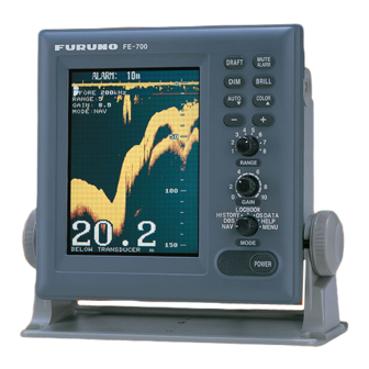
General SYSTEM CONFIGURATION The FE-700 consists of Display Unit ( FE701 ) , Distribution Box ( FE702 ), Transducer Switching Box ( EX-8 ) and Matching Box ( MB-502/MB-504 ). The Switching Box and Matching Box connected to switching box are supplied optionally. -
Page 9: Chapter 1. Circuit Description
Chapter 1. Circuit Description 1.1 GENERAL BLOCK DIAGRAM Downloaded from www.Manualslib.com manuals search engine... -
Page 10: Function Of Each Unit
1.2 FUNCTION OF EACH UNIT 1.2 FUNCTION OF EACH UNIT Display Unit (FE-701 ) Board/Unit Functions MAIN Board 1) Processes depth signal by the CPU and the gate array, and converts them into the video signal. (02P6280) 2) Receives panel signal. 3) Detects the depth. -
Page 11: Power Supply
1.3 POWER SUPPLY 1.3 POWER SUPPLY Either 24 VDC or 100-115/200-230 VAC ship's mains is connected to the Distribution Box. The connection on TB7 must be changed depending on ship's mains, as follows. 1) When ship's main is 100 to 115 VAC; Black Orange White... - Page 12 1.3 POWER SUPPLY Switching Regulator Circuit The switching regulator on the ANLG board generates 100 V for TX amplifier, 9 V for LCD inverter and 15/12/5 V for other circuits. Downloaded from www.Manualslib.com manuals search engine...
- Page 13 1.3 POWER SUPPLY Figure 1.5 Waveforms at A/B/C/D/E on the switching regulator circuit. Downloaded from www.Manualslib.com manuals search engine...
-
Page 14: Transmission Circuit
1.4 TRANSMISSION CIRCUIT 1.4 TRANSMISSION CIRCUIT The transmission amplifier circuit is commonly used for both frequencies, 50/200 kHz. The transmission frequency is set on the System Menu 3. Transmission carrier signal "TX0/TX1" are generated by Gate Array U10 on the MAIN board 02P6280 and supplied to the TX driver circuit. -
Page 15: Receiving Circuit
1.5 RECEIVING CIRCUIT 1.5 RECEIVING CIRCUIT The received signal is amplified by the Log Amplifier Circuit. Both 200 and 50 kHz RX circuits are located on the ANLG board and the one of RX circuits is selected by U9 in accordance with the System Menu 3 setting. -
Page 16: Display
1.6 DISPLAY 1.6 DISPLAY The TFT LCD module is employed for the presentations. The control circuit and fluorescent lamp for backlighting are molded in the LCD unit "EDTCA14QCF". The life of the fluorescent lamp is approx. 20,000 hours if it is used with max. brightness. High voltage for LCD backlighting is generated on the MAIN board and is outputed from J4-#1 and #2 to the LCD unit. - Page 17 I/O Signals of LCD Module I/O Signals of LCD Module Signal Specification/Function STH1 Source Driver Start Pulse 1 ( When RL is High ) Pulse for switching the output current of the Source Driver Control signal for switching the Video Data for the Source Driver CPH1 Source Driver Sampling Pulse 1 CPH2...
- Page 18 I/O Signals of LCD Module Figure 1.10 Output Waveforms from LCD interface circuit Downloaded from www.Manualslib.com manuals search engine...
-
Page 19: Chapter 2. Maintenance
Chapter 2. Maintenance 2.1 ADJUSTMENT ANLG board Measuring Point Ratings Adjuster Vcc (+5V) J5, #3 and GND ( TP1 ) +5±0.02 V R49, ANLG Board Switching frequency U3,#9 and U3, #7 ( GND ) 83.4~83.8 kHz R50, ANLG Board Figure 2.1 Adjuster on the ANLG board 2.2 REPLACEMENT OF LITHIUM BATTERY The battery on the MEM board must be replaced when the low battery alarm appears on the display. -
Page 20: Chapter 3. Troubleshooting
Chapter 3. Troubleshooting 3.1 DIAGNOSTIC TEST Function Test Function test is performed by the following key operation. 1. Press the POWER key while pressing any key. 2. Release the key when the optional mode selection display appears. 3. Press the [ - ] key to select the TEST. The following display appears. -
Page 21: Test Pattern
3.1 DIAGNOSTIC TEST Range, Gain and Mode knobs Operate the controls. The RANG and MODE control setting indications should be the same as actual control settings. The GAIN control setting indication should be among 0 to 235- 255. If some abnormal condition is obtained by controlling the RANGE and MODE knobs, the PANEL or MAIN board ( Gate array U10 ) is suspected to be defective. -
Page 22: Clearing The Memory
3.2 CLEARING THE MEMORY 3.2 CLEARING THE MEMORY To clear all data in the memory, follow the steps below. Factory settings are restored after this operation. 1. Turn on the power while pressing any key. Release the keys when the optional mode window appears. 2. -
Page 23: Inspection Of Each Board
3.4 INSPECTION OF EACH BOARD 3.4 INSPECTION OF EACH BOARD Board/Unit : MAIN board (02P6236) Signal In/Out Measuring Points Measured by Rating/Remarks FREQ Output ANLG Board Oscilloscope 50 kHz : J4, #21 and GND 200 kHz : (L=0 V, H=5 V) TX0/TX1 Output... - Page 24 3.4 INSPECTION OF EACH BOARD Board/Unit : MAIN board (02P6236) Signal In/Out Measuring Points Measured by Rating/Remarks Power Line J4, #3 and GND Multimeter +5±0.02V +12 V Power Line J4, #11 and GND Multimeter +12.0±0.5V +9 V Power Line J4, #13 and GND Multimeter +9.0±0.3V -15 V...
-
Page 25: Chapter 4. Parts Location
Chapter 4. Parts Location 4.1 DISPLAY UNIT ANLG Board ( 02P6281 ) Front Panel MAIN Board ( 02P6280 ) Chasiss Figure 4.1 Parts Assembly MAIN Board ( 02P6280 ) MEM Board ( 02P6282 ) Figure 4. 2 Front Panel Assembly Downloaded from www.Manualslib.com manuals search engine... - Page 26 LCD Unit EDTCA14QCF Figure 4.3 LCD Unit PANEL Board ( 02P6250 ) Gasket 02-1123-1061 Figure 4.4 Front Panel Downloaded from www.Manualslib.com manuals search engine...
- Page 27 U10(Gate Array) U1 ( CPU ) TP4 (GND) TP3 (+5V) TP5 (+15V) TP2 (+12V) TP1 (+9V) Figure 4.5 MAIN Board ( 02P6280 ) (Lithium Battery) Figure 4.6 MEM Board ( 02P6282 ) Downloaded from www.Manualslib.com manuals search engine...
- Page 28 LS1 ( Buzzer ) Figure 4.7 PANEL Board ( 02P6250 ) Downloaded from www.Manualslib.com manuals search engine...
- Page 29 Heat Sinking Plate (Vcc +5V ADJ) Preset Gain: 50kHz (Preset Gain: 200kHz) U3 (MB3759PF) ( Freq. Adj.) TP1( GND) J1 ( Power) J3 ( Data ) J2 ( XDR ) Figure 4.8 ANLG Board ( 02P6281 ) Downloaded from www.Manualslib.com manuals search engine...
-
Page 30: Distribution Box
4.2 DISTRIBUTION BOX (Power Switch) (02S1256-0) FUSE 1 FUSA 2 CONE Board ( 02P6283 ) TB5 TB6 Figure 4.9 Distribution Box ( FE702) F1 (3A) F2 (0.5A) F3 (0.5A) Figure 4.10 CONE Board ( 02P6283 ) Downloaded from www.Manualslib.com manuals search engine... -
Page 31: Matching Box
4.3 MATCHING BOX TO TRANSDUCER TO DISTRIBUTION 1 2 3 1 2 3 FREQ 50 kHz T-203BJ T-204B 50B-6B 200 kHz T-205AJ T-206A 200B-8B Figure 4.11 Matching Box ( MB502 ) Downloaded from www.Manualslib.com manuals search engine... -
Page 32: Switch Box
4.4 SWITCH BOX Figure 4.12 Switch Box, Front View Figure 4.13 Switch Box, Inside View Downloaded from www.Manualslib.com manuals search engine... -
Page 33: Chapter 5. Digital Interface (Iec 61162-1)
Chapter 5. Digital interface (IEC 61162-1) 5.1 I/O SENTENCES Input RMA, RMC, GLL, GGA, VTG, ZDA Output DPT, DBS, DBT 5.2 SENTENCE DESCRIPTION DPT - Depth 1MG Resolution A.224 (VII). Water depth relative to the transducer and offset of the measuring transducer. - Page 34 5.2 SENTENCE DESCRIPTION GGA - Global positioning system (GPS) fix data Time, position and fix related data for a GPS receiver. *Differential reference station ID, 0000-1023 *Age of differential GPS data *Unit of geoid height, m *Geoid height (-999 - 0999) *Unit of antenna height, m *Antenna height (-9999 - 99999) Checksum...
- Page 35 5.2 SENTENCE DESCRIPTION RMA - Recommended minimum specific LORAN-C data Position, course and speed data provided by a LORAN-C receiver. Time differences A and B are those used in computing latitude/longitude. Checksum is mandatory in this sentence. This sentence is transmitted at intervals not exceeding 2 s and is always accompanied by RMB when a destination waypoint is active.
- Page 36 5.2 SENTENCE DESCRIPTION VTG- Course over ground and ground speed The actual course and speed relative to the ground $--VTG, x.x, T, x.x, M, x.x, N, x.x, K*hh<CR><LF> Checksum Speed, km/h Speed, knots Course degrees magnetic Course degrees true ZDA - Time and date UTC, day, month, year and local time zone.
-
Page 37: Parts List
PARTS LIST UNIT NAME TYPE CODE NUMBER FE-701 MAIN Board Assembly(MAIN/MEM) 001229190 MAIN Board 02P6280 001229200 MEM Board 02P6282 001229220 ANLG Board 02P6281 001229240 PNL Board 02P6250 001389720 EDTCA14QCF 000142777 FE-702 CONE Board 02P6283 001229030 Downloaded from www.Manualslib.com manuals search engine... - Page 38 Downloaded from www.Manualslib.com manuals search engine...
- Page 39 Downloaded from www.Manualslib.com manuals search engine...
- Page 40 Downloaded from www.Manualslib.com manuals search engine...
- Page 41 Downloaded from www.Manualslib.com manuals search engine...
- Page 42 Downloaded from www.Manualslib.com manuals search engine...
- Page 43 Downloaded from www.Manualslib.com manuals search engine...
- Page 44 Downloaded from www.Manualslib.com manuals search engine...
- Page 45 Downloaded from www.Manualslib.com manuals search engine...
- Page 46 Downloaded from www.Manualslib.com manuals search engine...
- Page 47 Downloaded from www.Manualslib.com manuals search engine...
- Page 48 Downloaded from www.Manualslib.com manuals search engine...
- Page 49 Downloaded from www.Manualslib.com manuals search engine...
- Page 50 Downloaded from www.Manualslib.com manuals search engine...
- Page 51 Downloaded from www.Manualslib.com manuals search engine...
- Page 52 Downloaded from www.Manualslib.com manuals search engine...
- Page 53 Downloaded from www.Manualslib.com manuals search engine...
- Page 54 Downloaded from www.Manualslib.com manuals search engine...
- Page 55 Downloaded from www.Manualslib.com manuals search engine...
- Page 56 Downloaded from www.Manualslib.com manuals search engine...
- Page 57 Downloaded from www.Manualslib.com manuals search engine...
- Page 58 Downloaded from www.Manualslib.com manuals search engine...