Table of Contents
Advertisement
Quick Links
USER'S MANUAL
Of
NVIDIA
MCP73V
Platform Processor Chipset
M/B for LGA775
Quad Core
Ready
Intel Core Processor Family
NO. G03-IN73M3-F
Rev: 1.0
Release date: Apr. 2008
Trademark:
* Specifications and information contained in this documentation are furnished for information use only, and are
subject to change at any time without notice, and should not be construed as a commitment by manufacturer.
Advertisement
Table of Contents

Related Manuals for JETWAY IN73M3


Summary of Contents for JETWAY IN73M3
- Page 1 Platform Processor Chipset M/B for LGA775 Quad Core Ready Intel Core Processor Family NO. G03-IN73M3-F Rev: 1.0 Release date: Apr. 2008 Trademark: * Specifications and information contained in this documentation are furnished for information use only, and are subject to change at any time without notice, and should not be construed as a commitment by manufacturer.
-
Page 2: Table Of Contents
TABLE OF CONTENT CHAPTER 1 INTRODUCTION OF NVIDIA MCP73V MOTHERBOARD SERIES FEATURES OF MOTHERBOARD ..................1 1-1.1 SPECIAL FEATURES OF MOTHERBOARD............ 2 SPECIFICATION........................3 ITEM CHECKLIST ......................3 LAYOUT DIAGRAM & JUMPER SETTING ..............4 CHAPTER 2 HARDWARE INSTALLATION INSTALL SOCKET INTEL SUPPORTED INTEL PROCESSOR ......... 5 INSTALL MEMORY...................... -
Page 3: Chapter 1 Introduction Of Nvidia Mcp73V Motherboard Series
Chapter 1 Introduction of NVIDIA MCP73V Motherboard Series Features of motherboard The MCP73V chipset technology which supports the innovative 65nm Quad-Core, Dual-Core Intel® Core 2 Quad, Core 2 Duo (Code Name: Conroe) processors, 90nm Dual-Core Intel® Pentium® D Processor 8 and 9 Series processors , Pentium 4 and Celeron D with Intel® Hyper-Threading Technology. -
Page 4: 1-1.1 Special Features Of Motherboard
Some special features---CPU Thermal Throttling/ CPU Vcore 7-shift this motherboard are designed for power user to use the over-clocking function in more flexible ways. But please be caution that the over-clocking maybe causes the fails in system reliabilities. This motherboard provides the guaranteed performance and meets the demands of the next generation computing. -
Page 5: Specification
Specification Spec Description ∗ U- ATX form factor 4 layers PCB size: 24.5cm*18.5cm Design ∗ Chipset NVIDIA MCP73V Chipset ∗ Support Intel Pentium 4, Celeron D, Pentium D, Core 2 Duo and Core 2 Quad 775-Land LGA Package utilizes Flip-Chip Land Grid Array package processor ∗... -
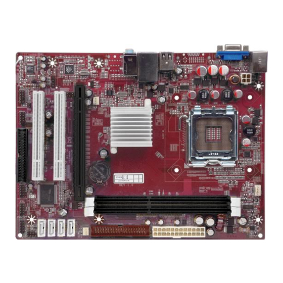
Page 6: Layout Diagram & Jumper Setting
Layout Diagram & Jumper Setting Line IN PS/2 Mouse VGA Connector USB1 Line OUT PS/2 Keyboard MIC IN USB Port ATX 12V Power Conn. CPU FAN PS2 KB/Mouse Port VGA Connector DDR2 Socket x 2 LGA775 CPU Socket KBMS/USB Power On Jumper (JP1) ATX Power Conn. -
Page 7: Chapter 2 Hardware Installation
Chapter 2 Hardware Installation 2-1 About Intel LGA775 CPU This motherboard provides a 775-pin surface mount, LGA775 Land Grid Array socket, referred to as the LGA775 socket supports Intel Core family processor in the 775 Pin package utilizes Flip-Chip Land Grid Array (FC-LGA) package technology. The CPU that comes with the motherboard should have a cooling FAN attached to prevent overheating. -
Page 8: Expansion Cards
Generally, installing DDRII SDRAM modules to your motherboard is very easy, you can refer to figure 2-4 to see what a 240-pin DDR SDRAM module looks like. NOTE! When you install DIMM module fully into the DIMM socket the eject tab should be locked into the DIMM module very firmly and fit into its indention on both sides. -
Page 9: Connectors
Chapter 3 Connectors, Headers & Jumpers Setting 3-1 Connectors Power Connector (24-pin block): ATXPWR1 Power Supply connector: This is a new defined 24-pins ROW1 ROW2 connector that usually comes with ROW1 ROW2 ROW1 ROW2 3.3V 3.3V ATX case. The ATX Power Supply 3.3V -12V allows... - Page 10 (6) Audio Line-In, Lin -Out, MIC, Surrback, Surround, CEN/LEF Connector: SURROUND1 / CN1 This Connector are 6 phone Jack for LINE-OUT, LINE-IN, MIC, Surrback, Surround, CEN/LEF Audio input to sound chip Line-in : (BLUE) Line-out : (GREEN) Audio output to speaker MIC : (PINK) Microphone Connector...
- Page 11 (8) Secondary IDE Connector (40-pin block): IDE1 This connector connects to the next set of Master and Slave hard disks. Follow the same procedure described for the primary IDE connector. You may also configure two hard disks to be both Masters using one ribbon cable on the primary IDE connector and another ribbon cable on the secondary IDE connector.
-
Page 12: Headers
3-2 Headers (1) Line-Out/MIC Header for Front Panel (9-pin): AUDIO1 This header connects to Front Panel Line-out, MIC connector with cable. Without install the cable, this header default setting is 5-6 short, 9-10 short. When you install the cable you have take off these jumpers. AUDIO Pin 1 Line-Out, MIC Headers... - Page 13 (7)USB Port Headers (9-pin) : USB2/USB3 / USB4 (Optional) These headers are used for connecting the additional USB port plug. By attaching an option USB cable, your can be provided with two additional USB plugs affixed to the back panel. USB2 USB3 Pin 1...
- Page 14 (9) CD Audio-In Headers (4-pin) : CDIN CDIN are the connectors for CD-Audio Input signal. Please connect it to CD-ROM CD-Audio output connector. CDIN CD Audio-In Headers (10) Serial COM Port header: COM1 is the 9-pin block pin-header. The On-board serial port can be disabled through BIOS SETUP.
-
Page 15: Chapter 4 Useful Help
Chapter 4 USEFUL HELP 4-1 HOW TO UPDATE BIOS Before updating the BIOS, users have to “Disable” the “Flash Part Write Protect” selection in “Miscellaneous Control” of BIOS SETUP. Otherwise the system the will not allow you to upgrade BIOS by Award Flash Utility. STEP 1.