Table of Contents
Advertisement
Quick Links
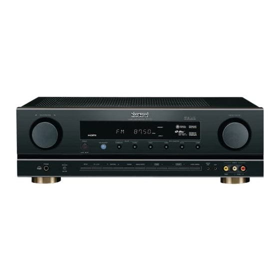
R-772
AUDIO/VIDEO RECEIVER
SAFETY PRECAUTIONS ................................... 1
SPECIFICATIONS .............................................. 2
TUNER SECTION .............................................. 7
BLOCK DIAGRAMS ............................................ 9
WIRING DIAGRAM ........................................... 12
CIRCUIT DESCRIPTION .................................. 13
ALIGNMENT PROCEDURES .......................... 18
CONTENTS
TROUBLESHOOTING....................................... 21
MECHANICAL PARTS LIST.............................. 25
EXPLODED VIEW ............................................. 26
ELECTRICAL PARTS LIST ............................... 27
IC'S FUNCTIONAL BLOCK DIAGRAMS........... 35
PRINTED CIRCUIT BOARDS ........................... 37
SCHEMATIC DIAGRAMS ................................. 45
R
Advertisement
Table of Contents

Related Manuals for Sherwood R-772


Summary of Contents for Sherwood R-772
-
Page 1: Table Of Contents
R-772 AUDIO/VIDEO RECEIVER CONTENTS SAFETY PRECAUTIONS ........1 TROUBLESHOOTING........21 SPECIFICATIONS ..........2 MECHANICAL PARTS LIST......25 TUNER SECTION ..........7 EXPLODED VIEW ..........26 BLOCK DIAGRAMS ..........9 ELECTRICAL PARTS LIST ....... 27 WIRING DIAGRAM ........... 12 IC’S FUNCTIONAL BLOCK DIAGRAMS... 35 CIRCUIT DESCRIPTION ........ -
Page 2: Safety Precautions
SAFETY PRECAUTIONS WARNING Before servicing this unit, familiarize yourself with the following precautions: 1. Many electrical and mechanical parts in this exposed metal parts of the cabinet, such as chassis have special safety characteristics that terminals, screw heads, and metal overlays, to often pass unnoticed and the protection be sure the set is safe to operate danger of afforded by them cannot necessarily be... -
Page 3: Specifications
SPECIFICATIONS Measuring methods are based on IHF and IEC standard 268-3 Measurements conditions,unless otherwise noted : Output resistive load = (6) ohms / Both channel driven Tone Direct ON , Other SW's : OFF Nominal input level : 5mV for MM, 0.5mV for MC, 500mV for general purpose inputs Power figures should be kept minimum 10min. - Page 4 NOMINAL DESCRIPTION INPUT FREQ. REMARK UNIT LIMIT L/R S/N RATIO, INPUT SHORT EXT IN INPUT 1kHz IHF-A FILTER FREQUENCY RESPONSE EXT IN INPUT 1W / 1kHz Ref. Hz~kHz 20~50 20~55 SURROUND BACK AMP SECTION * SPKR LEVEL:ALL 0dB * SPK SIZE:YES * EXT IN INPUT * TONE OFF * X-OVER:FULL RANGE NOMINAL...
- Page 5 DOLBY DIGITAL INPUT SECTION * INPUT : COAXIAL (CD DIGITAL) * SURROUND MODE : DOLBY DIGITAL * VOLUME POSISTION : 55dB * CONFIG1:SPK YES BACK-NO/X-OVER:ALL 80Hz * CONFIG2:SPK YES /SUBWOOFER,BACK-NO/X-OVER:FRONT FULL RANGE,OTHERS 80Hz * AT SPEAKER OUT Disc:LD VER 1.0 SPEC DESCRIPTION INPUT...
- Page 6 DOLBY-EX INPUT SECTION * INPUT : COAXIAL, CD DIGITAL * SURROUND MODE : DOLBY-EX * VOLUME POSISTION : 55dB * AT SPEAKER OUT SPK MODE YES,BACK-YES DOLBY-EX TEST Disc(TRACK 7) SPEC DESCRIPTION INPUT FREQ. CHAP UNIT NOMI. LIMIT OUT PUT LEVEL 1 KHz Disc : DOLBY-EX -23dB 700±70...
- Page 7 VIDEO SECTION * Load : Video output 75 ohm * MEASUREMENT POSITION : AT MONITOR OUT * DISC : TDV - 540 TEST DISC (ABEX) * TEST INSTRUMENT : SCOPE,VN30A1 (1) INPUT : C-VIDEO OUTPUT : C-VIDEO DESCRIPTION INPUT REMARK UNIT LIMIT NOMINAL...
-
Page 8: Tuner Section
TUNER SECTION Measuring methods in confirmity with IEC standard 315 Measurements condition FM : Radio frequency = 98.1MHz, Audio frequency = 1kHz Reference level = 1mV on ( 75ohms , 300ohms ) Deviation : MONO = ±75kHz, Stereo = ±67.5kHz±7.5kHz (A) Filter = B.P.F at STEREO MONO MONO = ±40kHz, Stereo = ±40kHz±7.5kHz (RDS) Test Point : TP 1 = 90.1MHz, TP 2 = 98.1MHz, TP 3 = 106.1MHz (100KHz STEP(A), 50KHz STEP(RDS)) - Page 9 AM SECTION Measurements condition AM - MW : Radio frequency = 1000/999kHz, Audio frequency = 400Hz Reference level = 74dBu/m), (50) ohms Modulation = 30% Test Point : MW TP1 = (600)kHz TP2 = (1000)kHz TP3 = (1400)kHz Test Point : TP1 = (594)kHz TP2 = (999)kHz TP3 = (1404)kHz...
-
Page 10: Block Diagrams
BLOCK DIAGRAMS - AUDIO (I) Model No.:R-772... - Page 11 BLOCK DIAGRAMS - VIDEO (II) Model No.:R-772...
- Page 12 BLOCK DIAGRAMS - POWER (III) Model No.:R-772...
-
Page 13: Wiring Diagram
WIRING DIAGRAM Model No.:R-772 PCB4-2(D.INPUT) PCB-RS232 PCB4(ST-BY) PCB1(MAIN) PCB3(AMP) PCB2(FRONT) -
Page 14: Circuit Description
CIRCUIT DESCRIPTION M3062LFGPFP : IC402 1. Pin Description 100 99 98 97 96 95 94 93 92 91 90 89 88 87 86 85 84 83 82 81 SUB_DATAOUT 24C16_SDA SUB_CLK 24C16_SCL PLL_CE FL_CE PLL_DATA FL_CLK RDS_DATA FL_DATA RDS_CLK RMC/IR SUB_IRQ BYTE MAIN_IRQ... - Page 15 2. Block Diagram Port P0 Port P1 Port P2 Port P3 Port P4 Port P5 Port P6 <VCC2 ports> <VCC1 ports> Internal peripheral functions A/D converter System clock (10 bits X 8 channels generation circuit Expandable up to 26 channels) Timer (16-bit) XIN-XOUT Output (timer A): 5...
- Page 16 3. Pin Function Pin No. Symbol Description SUB_DATAOUT Serial data signal Output to submicom SUB_CLK Output Clock Signal for submicom. Not used! FL_CE Output for chip enable of SC16315 FL_CLK Clock signal output for SC16315 FL_DATA Data signal output for SC16315 Input for remocon data.
- Page 17 Pin No. Symbol Description NJW1197_MUTE MUTE signal output for NJW1197. OSD_DATA Data signal output for LC74781 OSD_CLK Clock signal output for LC74781 OSD_CE Output for chip enable of LC74781 TA1270_SCL Serial data clock signal output for "TA1270BF" TA1270_SDA Serial data signal output for "TA1270BF" BU2090_CLK Clock signal output for BU2090 BU2090_DATA...
- Page 18 4. Key Table KEY IN 1(pin90) KEY IN 2(pin91) KEY IN 3(pin92) PRESET UP CONTROL UP TUNER 0V~0.14V SW717 SW718 SW719 PRESET DOWN CONTROL DOWN EXT_IN 0.15V~0.47V SW714 SW715 SW716 TUNE UP CH_LEVEL AUDIO 0.48V~0.85V SW711 SW712 SW713 TUNE DOWN OSD SETUP VIDEO 0.86V~1.2V...
-
Page 19: Alignment Procedures
ALIGNMENT PROCEDURES TUNER 1. Equipment Requried • Audio Generator • AM Standard Signal Generator (AM SSG) • Oscilloscope • Distortion Meter • AC Voltmeter • DC Voltmeter • FM Standard Signal Generator (FM SSG) • Frequency Counter • Stereo Modulator Note : Disconnect external FM antenna prior to alignment. - Page 20 2-3. FM Alignment • Output of signal generator should not be greater than necessary to obtain an optimum output reading. • Signal generator modulation : MAIN : 90%, PILOT : 10% • Signal frequency : 1kHz / Deviation : 75kHz •...
- Page 21 3-2. AM Alignment • Output of signal generator should not be greater than necessary to obtain an optimum output reading. • Signal generator modulation : 30% • Signal frequency : 400Hz • Modulation frequency : 600, 1000, 1400kHz • Switch : press the BAND Button to AM Signal generator Set frequency Equipment...
-
Page 22: Troubleshooting
TROUBLESHOOTING Symptom Cause and Remedy Ref No. Power On Failure A) AC-Cord check. 1. FLT does not light up. B) Power Trans (Main/ST-BY) check. 2. ST-BY LED does not light up. C) Fuse's disconnection check. F ( 300,301) D) Connector's disconnection or disjunction. Change or close insertion of the connector. - Page 23 Symptom Cause and Remedy Ref No. Bass / Treble Control Failure. A) Bass volume check. I.C401 1. Resister/Capacitor correction figure check. I.C401 PIN No. ( 9,10,13,14/11,15) 2. BASS VR's property inferior. B) TONE I.C check. I.C No. ( 401) 1. Signal IN/OUT terminal check. 2.
- Page 24 Symptom Cause and Remedy Ref No. 3)I2C Control Check. IC No.(1018) IC Pin No.(26,27) IC No.(1009) IC Pin No.(48,49) 4)DDC Check. IC No.(1018) IC Pin No.(28,29,33,34) 5)Hot Plug detect Check. JACK No.1001,1002,1003 Pin No.19 OSD Failure. A) I.C voltage check. I.C No.
- Page 25 Symptom Cause and Remedy Ref No. FM Failure. A) FM MUTE adjustment inferior. B) FRONT-END inferior. C) FM DET COIL inferior. D) PLL IC check. 1. PLL I.C B+( 5 )V check. 2. PLL control data check. (Data/CE/Clock) E) TUNER B+ voltage inferior. F) µ-COM I.C &...
-
Page 26: Mechanical Parts List
MECHANICAL PARTS LIST Model No.:R-772 DESCRIPTION Q'TY PARTS No. VER. DESCRIPTION Q'TY PARTS No. VER. Parts without Parts No. are not supplied. PCB TOTAL ASS'Y, INPUT INDICATOR, GUIDE LED 5160041003010S Parts without version mentioned are common ones. USA(120V/60Hz), G RDS(230V/50Hz) -
Page 27: Exploded View
EXPLODED VIEW Model No.:R-772... -
Page 28: Electrical Parts List
ELECTRICAL PARTS LIST Model No.:R-772 Parts without Parts No. are not supplied. DESCRIPTION REF No. DESCRIPTION Q'TY PARTS No. VER. REF No. Q'TY PARTS No. VER. CP416 CN.FPC 1.25MM (7P) L131007100010S C520 ELECT GE 85C 10 uF D040100087070S Parts without version mentioned are common ones. - Page 29 Model No.:R-772 REF No. DESCRIPTION Q'TY PARTS No. VER. REF No. DESCRIPTION Q'TY PARTS No. VER. REF No. DESCRIPTION Q'TY PARTS No. VER. R415-R421 METAL FILM 100PPM 10 ohm C060010065050S R514L/R CHIP THICK 470 ohm 1/16W C20004716M160S R580/R581 CARBON FILM...
- Page 30 Model No.:R-772 REF No. DESCRIPTION Q'TY PARTS No. VER. REF No. DESCRIPTION Q'TY PARTS No. VER. REF No. DESCRIPTION Q'TY PARTS No. VER. J394-J396 CN,WIRE 1P L045084006040S R744/R745 CHIP THICK 3.3 kohm 1/16W C20003326M160S C202SBL CERAMIC HIK AXIAL 220 pF...
- Page 31 Model No.:R-772 REF No. DESCRIPTION Q'TY PARTS No. VER. REF No. DESCRIPTION Q'TY PARTS No. VER. REF No. DESCRIPTION Q'TY PARTS No. VER. D201SBL 1SS133T, SWITCHING K000013300520S R206SL CARBON FILM 33 kohm 1/5W C00003336P520S R218SBL METAL FILM 100PPM 4.7 ohm...
- Page 32 Model No.:R-772 DESCRIPTION REF No. DESCRIPTION Q'TY PARTS No. VER. REF No. DESCRIPTION Q'TY PARTS No. VER. REF No. Q'TY PARTS No. VER. MISCELLANEOUS C865 CERAMIC CHIP HIK 0.1 uF D011104597160S C836 ELECT GE 85C 0.1 uF D040R10087080S C866 CERAMIC CHIP HIK 0.01 uF...
- Page 33 Model No.:R-772 REF No. DESCRIPTION Q'TY PARTS No. VER. REF No. DESCRIPTION Q'TY PARTS No. VER. REF No. DESCRIPTION Q'TY PARTS No. VER. C569 CERAMIC CHIP HIK 0.022 uF D011223777160S C569 CERAMIC CHIP HIK 0.022 uF D011223777160S R585C CHIP THICK...
- Page 34 Model No.:R-772 DESCRIPTION REF No. DESCRIPTION Q'TY PARTS No. VER. DESCRIPTION REF No. Q'TY PARTS No. VER. REF No. Q'TY PARTS No. VER. C1005/C1006 CERAMIC CHIP HIK 0.1 uF D011104177101S C1153-C1155 CERAMIC CHIP HIK 0.1 uF D011104177101S C1330 CERAMIC CHIP HIK 0.1 uF...
- Page 35 Model No.:R-772 REF No. DESCRIPTION Q'TY PARTS No. VER. REF No. DESCRIPTION Q'TY PARTS No. VER. REF No. DESCRIPTION Q'TY PARTS No. VER. Q1022-Q1024 KTC2875B(MB), NPN J5222875B0010S R1207/R1208 CHIP THICK 100 kohm 1/16W C20001046M101S R1377 CHIP THICK 470 kohm 1/16W...
-
Page 36: Ic's Functional Block Diagrams
IC’S FUNCTIONAL BLOCK DIAGRAMS Model No.:R-772 M30302FEPFP : IC1024(SUB MICOM) 3. Pin Function 1. Pin Description Pin No. Symbol Description Pin No. Symbol Description U_SUB_CE Chip Enable ( controled by Main Micom) SIL9135_INT_U SIL9135 Interrupt request U_SUB_CCLK Serial control clock ( controled by Main Micom) - Page 37 Model No.:R-772 CS495313 : IC1005 TA1270BF : IC504 Stereo Audio Inptut Stereo Audio Inptut DSP CORE Peripheral Debug Controller Stereo Audio Inptut Controller Controller Stereo Audio Inptut or 4Kx32 Compressed Audio Input SRAM Ext (64 bit) 4Kx32 Stereo Audio Outptut...
-
Page 38: Printed Circuit Boards
PRINTED CIRCUIT BOARDS (I) Model No.:R-772 PCB1 (MAIN-TOP) - Page 39 PRINTED CIRCUIT BOARDS (II) Model No.:R-772 PCB1 (MAIN-BOTTOM)
- Page 40 PRINTED CIRCUIT BOARDS (III) Model No.:R-772 PCB2 (FRONT-TOP) PCB2 (FRONT-BOTTOM)
- Page 41 PRINTED CIRCUIT BOARDS (IV) Model No.:R-772 PCB3 (AMP-TOP) PCB3 (AMP-BOTTOM)
- Page 42 PRINTED CIRCUIT BOARDS (V) Model No.:R-772 PCB4 (STAND BY-TOP) PCB4 (STAND BY-BOTTOM)
- Page 43 PRINTED CIRCUIT BOARDS (VI) Model No.:R-772 PCB5 (VIDEO-TOP) PCB5 (VIDEO-BOTTOM)
- Page 44 PRINTED CIRCUIT BOARDS (VII) Model No.:R-772 PCB6 HDMI MULTI LAYER - 1 LAYER (TOP) PCB6 HDMI MULTI LAYER - 2 LAYER (VCC) PCB6 HDMI MULTI LAYER - 3 LAYER (INTER1)
- Page 45 PRINTED CIRCUIT BOARDS (VIII) Model No.:R-772 PCB6 HDMI MULTI LAYER - 4 LAYER (INTER2) PCB6 HDMI MULTI LAYER - 6 LAYER (BOTTOM) PCB6 HDMI MULTI LAYER - 5 LAYER (GND)
-
Page 46: Schematic Diagrams
SCHEMATIC DIAGRAMS (I) Model No.:R-772 L-OUT A_FL R-OUT +12V TUNED A_FR PLL DO PLL CLK PLL DI PLL CE COMP_MUTE COMP_DET S-VIDEO DET RDS DATA RDS CLK C-VIDEO DET BU2090_DTA BU2090_CLK TA1270_SDA TA1270_SCL OSD_CE OSD_CLK OSD_DATA R2_MUTE SW_PREOUT VIDEO4_IN ROOM2_L... - Page 47 SCHEMATIC DIAGRAMS (II) Model No.:R-772 PCB1 (MAIN-2)
- Page 48 SCHEMATIC DIAGRAMS (III) Model No.:R-772 PCB2-2 PCB2-1 (POWER SW) (MULTI JOG) PCB2 (FRONT) PCB2-3 (H/P) PCB2-4 (MIC SETUP)
- Page 49 SCHEMATIC DIAGRAMS (IV) Model No.:R-772 PCB3 (AMP)
- Page 50 SCHEMATIC DIAGRAMS (V) Model No.:R-772 PCB4-1 (SPEAKER) PCB4-2 (D. INPUT) PCB4-3 (CONNECTION) PCB4 (ST-BY)
- Page 51 SCHEMATIC DIAGRAMS (VI) Model No.:R-772 PCB5 (VIDEO)
- Page 52 SCHEMATIC DIAGRAMS (VII) Model No.:R-772 PCB6 (HDMI)
- Page 53 SCHEMATIC DIAGRAMS (VIII) Model No.:R-772...
- Page 54 SCHEMATIC DIAGRAMS (IX) Model No.:R-772 DIR WITH CODEC...
- Page 55 SCHEMATIC DIAGRAMS (X) Model No.:R-772 SUB MICOM...
- Page 56 SCHEMATIC DIAGRAMS (XI) Model No.:R-772...
- Page 57 SCHEMATIC DIAGRAMS (XII) Model No.:R-772 TUNER ASS’Y(A ONLY)
- Page 58 SCHEMATIC DIAGRAMS (XIII) Model No.:R-772 TUNER ASS’Y(RDS ONLY)
- Page 59 Printed in Korea 07K11 5737045850010...