
Related Manuals for CAME CAME GARD PT Brushless


Summary of Contents for CAME CAME GARD PT Brushless
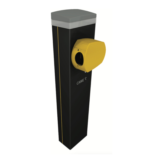
- Page 1 Automatic road barriers FA01440-EN GARD PT Brushless GPT40AGS GPT40RGS GPT40AGL English INSTALLATION MANUAL...
- Page 2 DEVICE MANUAL RELEASE Releasing the device may be dangerous for the user, if the boom fastening has been damaged or if the boom is no longer intact, as the result of an accident or installation error. In these cases, the tensioned springs no longer guarantee that the boom is balanced. The boom may suddenly rotate when being released. With the gearmotor released, the operator does not work.
- Page 3 GENERAL PRECAUTIONS FOR INSTALLERS Important safety instructions. Please follow all of these instructions. Improper installation may cause serious bodily harm. Before continuing, please also read the general precautions for users. Only use this product for its intended purpose. Any other use is hazardous. • The manufacturer cannot be held liable for any damage caused by improper, unreasonable or erroneous use.
-
Page 4: Dismantling And Disposal
DISMANTLING AND DISPOSAL CAME S.p.A. employs an Environmental Management System at its premises. This system is certified and compliant with the UNI EN ISO 14001 standard to ensure that the environment is respected and safeguarded. Please continue safeguarding the environment. At CAME we consider it one of the fundamentals of our operating and market strategies. - Page 5 PRODUCT DATA AND INFORMATION This symbol shows which parts to read carefully. This symbol shows which parts describe safety issues. This symbol shows what to tell users. The measurements, unless otherwise stated, are in millimetres. Description 803BB-0070 GPT40AGS - Automatic barrier with reversible gearmotor and brushless motor; painted aluminium cabinet. 803BB-0140 GPT40RGS - Automatic barrier powered at 120 V AC with reversible gearmotor and brushless motor;...
-
Page 6: Description Of Parts
Description of parts Barrier Boom anchoring plate Cabinet Fastening flange Inspection hatch Anti-shearing cover Anchoring plate Protective cover fastening screws Anchoring bracket Control panel Filter cover Transformer cover Mechanical stop for the boom adjustment Lock for release Gear motor with encoder Line fuse Lever arm Electric lock *... - Page 7 Control board 1 -Programming buttons 16 -Terminal board for NC contact for gearmotor release 17 -Terminal board associated with the RSE_2 connector for CRP or CAME KEY 2 -Display connection 3 -USB stick connector 18 -Terminal board associated with the RSE_1 connector for paired or alternate...
- Page 8 Size 206.5 3800 max Cable types and minimum thicknesses Cable length (m) up to 20 from 20 to 30 Power supply 230 V AC 3G x 1.5 mm2 3G x 2.5 mm2 24 V AC/DC flashing beacon 2 x 1 mm2 2 x 1 mm2 TX Photocells 2 x 0.5 mm2...
-
Page 9: Installation
INSTALLATION The following illustrations are examples only. The space available for fitting the operator and accessories varies depending on the area where it is installed. It is up to the installer to find the most suitable solution. In case of manual handling, have one person for every 20 kg that needs hoisting; for non-manual handling, use proper hoisting equipment in safe conditions. When the operator is being fixed in place, it may be unstable and overturn. - Page 10 Fill the hole with soil around the concrete block. Remove the nuts from the screws. Thread the electrical cables into the tubes so that they protrude by about 1500 mm. Preparing the barrier With the cover open, the operator does not work. ❸...
-
Page 11: Boom Installation
Changing the boom opening direction The barrier is set up for installation on the left. Check that the lever arm is positioned vertically. Remove the mechanical stop. Attach the mechanical stop to the right of the lever arm. Edit the parameter for the function [Opening direction]. <... - Page 12 Fit the boom into the fastening flange. Tighten the screws firmly. Cut the slot-cover profiles to the same size as the boom slot minus 10 millimetres. Insert the slot-cover profiles into the grooves on both sides of the boom. Fit the rubber end cap in position. Insert the anti-impact rubber profile into the groove, aligning it with the end cap.
-
Page 13: Boom Set Up
Boom set up Before adjusting the boom, check the accessories you want to fit and the passage clearance width. Simple boom means the boom complete with slot cover, cap and rubber profile. Passage width clearance / Duty-cycle < 2.5 m / 80% <... - Page 14 Correct the boom’s vertical position Release the gearmotor. Open the inspection hatch. Turn the mechanical stop until you reach the desired boom position. Fasten the mechanical stop with a locknut. Lock the gearmotor ❶ ❷...
-
Page 15: Electrical Connections
ELECTRICAL CONNECTIONS Passing the electrical cables The electrical cables must not touch any parts that may overheat during use (such as the motor and transformer). Make sure that the moving mechanical parts are suitably far away from the wiring. The cables must pass through the ferrite included in the supply. Power supply Make sure the mains power supply is disconnected during all installation procedures. - Page 16 Maximum capacity of contacts Device Output Power supply (V) Power (W) Accessories 10 - 11 24 AC Additional light 10 - E1 24 AC Flashing beacon 10 - E1 24 AC Operator status warning light 10 - 5 24 AC RGB LED strip 13,5 The sum of the connected accessories input must not exceed 40 W.
-
Page 17: Signalling Devices
Signalling devices Additional light It increases the light in the manoeuvring area. Additional flashing beacon It flashes when the operator opens and closes. Operator status warning light It notifies the user of the operator status. RGB LED strip and/or RGB crown If the red LEDs are flashing, the operator is moving. - Page 18 DIR / DELTA-S photocells DIR / DELTA-S photocells Standard connection Connection with safety test Multiple photocell pairs can be connected. Multiple photocell pairs can be connected. See function [F5] Safety devices test. S1GND FA FC S1GND FA FC 11 E1 E6 TS 1 3 3P 4 2 CX CY CZ 11 E1 E6 TS 1...
-
Page 19: Getting Started
PROGRAMMING Programming button functions ESC button The ESC button is used to perform the operations described below. Exit the menu Delete the changes Go back to the previous screen Stop the operator < > buttons The <> buttons are used to perform the operations described below. Navigate the menu Increase or decrease values Open or close the operator... - Page 20 CY input Associate a function with the CY input. CY input OFF (Default) C1 = Reopen while closing (photocells) C4 = Obstacle standby (photocells) C5 = Immediate closure at the travel end during opening C7 = Reopen while closing (sensitive edges) C9 = Immediate closure at the travel end during opening with obstacle standby during closure C10 = Immediate closure during opening with obstacle standby during closure (NO...
- Page 21 Open warning light Barrier status warning. Open warning light 0 = Warning light on (default) - The light stays on when the boom is moving or open. 1 = Warning light flashing - The warning light flashes every half a second when the boom is opening and remains on when the boom is open.
- Page 22 Closing speed Set the closing speed (percentage of maximum speed). The percentage values automatically adapt to the value entered in the function [Boom length]. Closing speed from 60% to 100% (Default 50%) Travel sensitivity Adjust the obstruction detection sensitivity during boom travel. Travel sensitivity 10% to 100% (Default 100%) - 10% = maximum sensitivity - 100% = minimum sensitivity...
- Page 23 The operation can be carried out by using a transmitter or another control device. The boards that manage the control devices (AF - R700 - R800) must be inserted into the connectors. Download the LIST OF REGISTERED USERS form from the docs.came.com portal by typing in L20180423. New user...
- Page 24 Remove user Remove one of the registered users. Remove user OFF (Default) No. 1 > 250 Use the arrows to choose the number associated with the user you want to remove. Alternatively, the control device associated with the user you want to remove can be activated.
-
Page 25: Import/Export Data
FW version Display the firmware version number and the GUI installed. FW version Update the FW from USB Update the firmware version of the device. The function is displayed only when a USB memory stick is inserted. Make sure the USB stick contains the firmware update file. Update the FW from USB OFF (Default) Import/export data... -
Page 26: Final Operations
FINAL OPERATIONS ❶ ❹ ❸ ❷... - Page 27 PAIRED OPERATION Two connected operators are controlled with one command. Electrical connections Connect the two electronic boards with a UTP CAT 5 cable. Fit an RSE card on both control boards, using the RSE_1 connector. Connect up the electrics for the devices and accessories. For information on connecting the electrics for the devices and accessories, please see the “ELECTRICAL CONNECTIONS”...
-
Page 28: Alternate Operation
ALTERNATE OPERATION The first barrier opens, the vehicle passes, the first barrier closes, the second barrier opens, the vehicle passes and the second barrier closes. Electrical connections Connect the two electronic boards with a UTP CAT 5 cable. Fit an RSE card on both control boards, using the RSE_1 connector. Connect up the electrics for the devices and accessories. - Page 29 ONLY OPEN command (2-3) on barrier B OPEN-CLOSE command (2-7) on barrier A or B for emergency opening...
- Page 30 MCBF Models GPT40 Std boom L = 3.05 m 4.000.000 Boom L = 4.05 m -0 % Boom L = 3.05 m with joint -0 % Boom L = 4.05 m with joint -0 % The GARD PT barrier has been designed to perform up to 4 million cycles. Thanks to its ultra-efficient brushless motor, it is extremely reliable and requires very little maintenance.
-
Page 31: Error Messages
ERROR MESSAGES Adjustment error Encoder failure error Service test failure error Operating time error Open release-hatch error Obstacle detected during closing Obstacle detected during opening The maximum number of obstacles detected consecutively has been exceeded Serial communication error Incompatible transmitter error Open SLAVE-motor hatch error Arm/boom drop-down error on ARM connector USB device error... - Page 32 CAME S.p.A. Via Martiri della Libertà, 15 31030 Dosson di Casier Treviso - Italy Tel. (+39) 0422 4940 Fax (+39) 0422 4941...