
Related Manuals for CAME GARD PT Brushless


Summary of Contents for CAME GARD PT Brushless
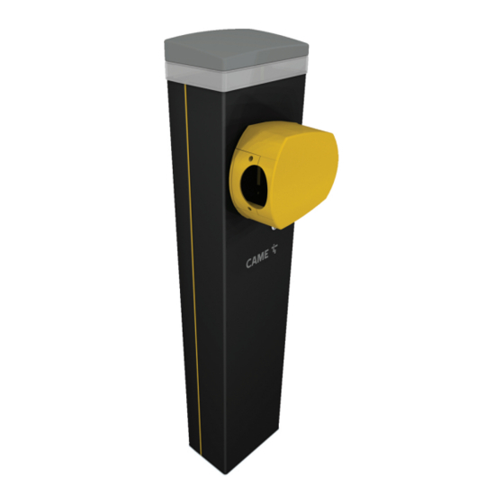
- Page 1 Barriere stradali automatiche FA01332M04 GARD PT Brushless GPT40AGS Italiano EN English FR Français RU Русский MANUALE DI INSTALLAZIONE...
- Page 2 SBLOCCO MANUALE DEL DISPOSITIVO L’operazione di sblocco può rappresentare un pericolo per l’utente, nel caso in cui le condizioni ottimali di fissaggio e integrità dell'asta, siano state compromessa da un incidente o da errori di montaggio. In questi casi, le molle in tensione non garantiscono più il bilanciamento dell'asta che in fase di sblocco potrebbe ruotare bruscamente. Con il motoriduttore sbloccato, l'automazione non funziona.
-
Page 3: Avvertenze Generali Per L'installatore
AVVERTENZE GENERALI PER L'INSTALLATORE Importanti istruzioni di sicurezza. Seguire tutte le istruzioni, in quanto un'installazione non corretta può portare a lesioni gravi. Prima di procedere, leggere anche le avvertenze generali per l'utilizzatore. Il prodotto deve essere destinato solo all’uso per il quale è stato espressamente studiato e ogni altro uso è da considerarsi pericoloso. - Page 4 CAME S.p.A. implementa all’interno dei propri stabilimenti un Sistema di Gestione Ambientale certificato e conforme alla norma UNI EN ISO 14001 a garanzia del rispetto e della tutela dell’ambiente. Vi chiediamo di continuare l’opera di tutela dell’ambiente, che CAME considera uno dei fondamenti di sviluppo delle proprie strategie operative e di mercato, semplicemente osservando brevi indicazioni in materia di smaltimento: SMALTIMENTO DELL’IMBALLO...
-
Page 5: Descrizione Delle Parti
DATI E INFORMAZIONI SUL PRODOTTO Legenda Questo simbolo indica parti da leggere con attenzione. Questo simbolo indica parti riguardanti la sicurezza. Questo simbolo indica cosa comunicare all’utente. Le misure, se non diversamente indicato, sono in millimetri. Descrizione GPT40AGS - Barriera automatica con motoriduttore reversibile e motore brushless; armadio in alluminio verniciato. Destinazione d'uso Soluzione ideale per l’utilizzo carraio intensivo Ogni installazione e uso difformi da quanto indicato nel seguente manuale sono da considerarsi vietate.. -
Page 6: Scheda Elettronica
Scheda elettronica 1 - Tasti per la programmazione 16 - Morsettiera per contatto NC per sblocco motoriduttore 17 - Morsettiera associata al connettore RSE_2 per collegamento CRP o CAME 2 - Display 3 - Connettore per chiavetta USB 18 - Morsettiera associata al connettore RSE_1 per collegamento abbinato o... - Page 7 Dimensioni 206.5 3800 max Limiti di impiego MODELLI GPT40AGS Larghezza max. passaggio utile (m) Dati tecnici MODELLI GPT40AGS Alimentazione (V - 50/60 Hz) 230 AC 50/60Hz Alimentazione motore (V) 36 DC Consumo in stand-by (W) Potenza (W) Termo-protezione trasformatore (°C) Corrente assorbita (A) 1,5 (230 V AC) Temperatura d’esercizio (°C)
- Page 8 Tipi di cavi e spessori minimi LUNGHEZZA DEL CAVO (m) < 10 da 10 a 20 da 20 a 30 Alimentazione 230 V AC 3G x 1,5 mm² 3G x 1,5 mm² 3G x 2,5 mm² Lampeggiatore 24 V AC - DC 2 x 1 mm²...
-
Page 9: Installazione
INSTALLAZIONE Le seguenti illustrazioni sono solo esempi in quanto lo spazio per il fissaggio dell’automazione e degli accessori varia a seconda della zona di installazione. Spetta all’installatore scegliere la soluzione più adatta. Nel caso di movimentazione manuale prevedere una persona per ogni 20 kg da sollevare; nel caso di movimentazione non manuale utilizzare opportuni mezzi per il sollevamento in sicurezza. - Page 10 Riempire di terra lo scavo attorno al blocco di cemento. Togliere i dadi dalle viti. Inserire i cavi elettrici nei tubi fino a farli uscire di 1500 mm circa. Preparazione della barriera Con il coperchio aperto, l'automazione non funziona. ❸ ❷...
- Page 11 Cambio del senso di apertura dell'asta La barriera e predisposta per l'installazione a sinistra. 1 - Verificare che il braccio della leva sia posizionato in verticale. 2 - Togliere il fermo meccanico. 3 - Fissare il fermo meccanico a destra del braccio leva. 4 - Cambiare il parametro nella funzione [ Direzione apertura].
- Page 12 Inserire l'asta nella flangia di fissaggio. Serrare con forza le viti. 1 - Tagliare i profili copri cava della stessa misura della cava dell'asta meno 10 millimetri. 2 - Inserire i profili copri cava nelle apposite scanalature su entrambi i lati dell'asta. 3 - Inserire il tappo terminale di gomma nell'apposita sede.
- Page 13 Composizione dell'asta Prima di regolare l'asta, verificare gli accessori da applicare e la luce di passaggio. Per asta semplice si intende l'asta completa di copri-cava, tappo e profilo in gomma. Passaggio utile / Intermittenza lavoro < 2,5 m / 80% <...
- Page 14 Correggere la posizione verticale dell'asta Sbloccare il motoriduttore Aprire lo sportello di ispezione. 1 - Ruotare il fermo meccanico fino ad ottenere la posizione desiderata dell'asta. 2 - Fissare il fermo meccanico con il controdado. Bloccare il motoriduttore ❶ ❷...
-
Page 15: Collegamenti Elettrici
COLLEGAMENTI ELETTRICI Passaggio dei cavi elettrici I cavi elettrici non devono entrare in contatto con parti che possono riscaldarsi durante l'uso (per esempio: motore e trasformatore). Assicurarsi che gli elementi meccanici in movimento abbiano un'adeguata distanza dal cablaggio realizzato. I cavi devono passare attraverso la ferrite in dotazione. 1 Alimentazione Durante tutte le fasi dell’installazione assicurarsi di operare fuori tensione. -
Page 16: Dispositivi Di Comando
Dispositivi di segnalazione 1 Lampada supplementare Aumenta l'illuminazione nella zona di manovra. Portata massima del contatto 10 - E1 24 V AC/DC - 20 W 2 Lampeggiatore supplementare B GND B GND FCA CM1 FCC CM2 Lampeggia durante le fasi di apertura e chiusura dell'automazione. -
Page 17: Dispositivi Di Sicurezza
Dispositivi di sicurezza Collegare i dispositivi di sicurezza agli ingressi CX, CY e/o CZ. In fase di programmazione, configurare il tipo di azione che deve essere svolta dal dispositivo collegato all'ingresso. Se non vengono utilizzati, i contatti CX CY CZ devono essere disattivati in fase di programmazione. Fotocellule DELTA Fotocellule DELTA Collegamento standard... - Page 18 PROGRAMMAZIONE Funzione dei tasti di programmazione 1 Tasto ESC Il tasto ESC permette di eseguire le operazioni di seguito descritte. Uscire dal menu Annullare le modifiche Tornare alla schermata precedente Arrestare l'automazione 2 Tasti < > I tasti < > permettono di eseguire le operazioni di seguito descritte. Navigare attraverso le voci del menu Incrementare o decrementare un valore Chiudere o aprire l'automazione...
- Page 19 Ingresso CZ Associa una funzione all’ingresso CZ. Ingresso CZ OFF (Default) C1 = Riapertura durante la chiusura (Fotocellule) C4 = Attesa ostacolo (Fotocellule) C5 = Chiusura immediata a fine corsa in apertura C7 = Riapertura durante la chiusura (bordi sensibili) C9 = chiusura immediata a finecorsa in apertura con attesa ostacolo durante la chiusura C10 = chiusura immediata durante l'apertura con attesa ostacolo durante la chiusura...
- Page 20 Lampada E1 Permette di scegliere il tipo di dispositivo collegato all'uscita. Lampada E1 0 = Lampeggiatore (Default) 1 = Lampada ciclo La lampada rimane spenta se non viene impostato un tempo di chiusura automatica. Ch. Automatica Imposta il tempo che deve trascorrere prima che si attivi la chiusura automatica, una volta che è stato raggiunto il punto di finecorsa in apertura. La funzione non si attiva nei casi in cui: intervengano dispositivi di sicurezza per la rilevazione di un ostacolo, dopo uno stop totale o in caso di mancanza di tensione.
- Page 21 Passaggio parametri MASTER-SLAVE Abilita la condivisione dei parametri programmati sulla barriera Master con la barriera Slave. Compare solo se la funzione F49 è impostata in Abbinato o Bussola. Passaggio parametri MASTER- OFF (Default) SLAVE Direzione apertura Imposta la direzione di apertura dell'asta. Direzione apertura 0 = Verso sinistra (Default) 1 = Verso destra...
- Page 22 L’operazione può essere svolta mediante un trasmettitore o altro dispositivo di comando. Le schede che gestiscono i dispositivi di comando (AF - R700 - R800) devono essere innestate nei connettori. Scaricare dal portale docs.came.com il modulo ELENCO UTENTI REGISTRATI, digitando L20180423. Nuovo Utente...
-
Page 23: Messa In Funzione
Reset parametri Ripristina le impostazioni di fabbrica ad esclusione delle funzioni: [Decodifica radio], [Lunghezza asta] e le impostazioni relative alla taratura della corsa. Reset parametri Conteggi manovre Permette di visualizzare il numero di manovre effettuate dall'automazione (1 = 1000 manovre). Conteggi manovre Versione FW Visualizza il numero della versione firmware e GUI installate. -
Page 24: Operazioni Finali
OPERAZIONI FINALI ❶ ❹ ❸ ❷... - Page 25 FUNZIONAMENTO ABBINATO Comando unico di due automazioni collegate. Collegamenti elettrici Collegare le due schede elettroniche con un cavo tipo UTP CAT 5. Inserire una scheda RSE su entrambe le schede elettroniche, utilizzando il connettore RSE_1. Procedere con il collegamento elettrico dei dispositivi e degli accessori. Per i collegamenti elettrici dei dispositivi e degli accessori, vedere capitolo COLLEGAMENTI ELETTRICI.
-
Page 26: Modalità Di Funzionamento
FUNZIONAMENTO A BUSSOLA Apertura della prima barriera, passaggio del veicolo, chiusura della prima barriera, apertura della seconda barriera, passaggio del veicolo e chiusura della seconda barriera. Collegamenti elettrici Collegare le due schede elettroniche con un cavo tipo UTP CAT 5. Inserire una scheda RSE su entrambe le schede elettroniche, utilizzando il connettore RSE_1. - Page 27 2 - Comando SOLO APRE (2-3) sulla barriera B 3 - Comando APRE-CHIUDE (2-7) sulla barriera A o B per apertura di emergenza...
- Page 28 MCBF Modelli 803BB-0070 Asta std L=3,05 m Asta L = 4,05 m -0 % Asta L = 3,05 m con snodo -0 % Asta L = 4,05 m con snodo -0 % Le percentuali indicano di quanto si debba ridurre il numero di cicli in relazione al tipo e numero di accessori installati. Il tipo di intervento e la frequenza di manutenzione sono decisi dall'installatore, considerando l'uso, il luogo di installazione e il numero di cicli giornalieri.
-
Page 29: Messaggi Di Errore
MESSAGGI DI ERRORE Errore di taratura Errore rottura encoder Errore di test servizi fallito Errore tempo di lavoro Errore sportello sblocco aperto Ostacolo rilevato durante la chiusura Ostacolo rilevato durante l'apertura Superato il numero massimo di ostacoli rilevati consecutivamente Errore comunicazione seriale Errore trasmettitore non compatibile Errore sportello aperto del motore SLAVE Errore caduta braccio/asta su connettore ARM... - Page 32 CAME S.p.A. Via Martiri della Libertà, 15 31030 Dosson di Casier Treviso - Italy Tel. (+39) 0422 4940 Fax (+39) 0422 4941...
- Page 33 Automatic road barriers FA01332-EN GARD PT Brushless GPT40AGS English INSTALLATION MANUAL...
- Page 34 DEVICE MANUAL RELEASE The unlocking operation may constitute a danger to the user, in case the correct boom fastening and conditions have been compromised by an accident or by installation errors. In these cases, the tensioned springs no longer guarantee the boom balancing which could suddenly rotate during the unlocking phase. With unlocked gearmotor, the operator does not work.
- Page 35 GENERAL PRECAUTIONS FOR INSTALLERS Important safety instructions. Follow all of these instructions. Improper installation can cause serious bodily harm. Before continuing, also read the general precautions for users. Use this product only for its specifically intended use. Any other use is hazardous. The manufacturer can not be held liable for any damage caused by improper, unreasonable, and erroneous use.
-
Page 36: Dismantling And Disposal
DISMANTLING AND DISPOSAL CAME S.p.A. employs an Environmental Management System at its premises. This system is certified and compliant with the UNI EN ISO 14001 regulation standard to ensure that the environment is respected and safeguarded. Please continue safeguarding the environment. At CAME we consider it one of the fundamentals of our operating and market strategies. -
Page 37: Intended Use
PRODUCT DATA AND INFORMATION Legend This symbol shows which parts to read carefully. This symbol shows which parts describe safety issues This symbol shows which parts to tell users about. The measurements, unless otherwise stated, are in millimeters. Description GPT40AGS - Automatic barrier with reversible gearmotor and brushless motor; painted aluminium cabinet. Intended use The ideal solution for passage ways with heavy transit flows Any installation and/or use other than that specified in this manual is forbidden.. -
Page 38: Control Board
Control board 1 - Buttons for programming 16 - Terminal board for NC contact for gearmotor release 17 - Terminal block associated with the RSE_2 connector for CRP or CAME KEY 2 - Display connection 3 - USB stick connector... - Page 39 Dimensions 206.5 3800 max Limits to use MODELS GPT40AGS Maximum clearance width of the passage (m) Technical data MODELS GPT40AGS Power supply (V - 50/60 Hz) 230 AC 50/60Hz Motor power supply (V) 36 DC Stand-by consumption (W) Power (W) Transformer thermal protection (°C) Current draw (mA) 1.5 (230 V AC)
- Page 40 Cable types and minimum thicknesses CABLE LENGTH (m) < 10 from 10 to 20 from 20 to 30 230 V AC Power supply 3G x 1.5 mm² 3G x 1.5 mm² 3G x 2.5 mm² 24 V AC - DC Flashing light 2 x 1 mm²...
-
Page 41: Installation
INSTALLATION The following illustrations are just examples, as the space available for fitting the operator and accessories varies depending on the area where it is installed. In case of manual handling, have one person for every 20 kg that need hoisting; for non manual handling use proper hoisting equipment in safe conditions. - Page 42 Fill the hole with earth around the concrete block. Remove the nuts from the bolts. Fit the electric cables into the tubes so that they come out about 1500 mm. Preparing the barrier With the cover open, the operator does not work. ❸...
-
Page 43: Boom Installation
Change of the boom opening direction The barrier is set up for installing on the left. 1 - Check that the lever arm is positioned vertically. 2 - Remove the mechanical stop. 3 - Attach the mechanical stop to the right of the lever arm. 4 - Edit the parameter in function [ Opening direction]. - Page 44 Fit the boom into the fastening flange Tighten the screws firmly. 1 - Cut the slot cover profiles of the same size as the boom slot minus 10 millimeters. 2 - Insert the slot cover profiles in the appropriate grooves on both sides of the boom. 3 - Fit the rubber terminal cap into the corresponding housing 4 - Insert the anti-impact rubber profile into the groove, making it fit with the end cap.
-
Page 45: Boom Set Up
Boom set up Before adjusting the boom, check the accessories you want to fit and the passage clearance width. Simple boom means the boom complete with slot cover, cap and rubber profile. Passage width clearance / Duty-cycle < 2.5 m / 80% <... - Page 46 Correct the boom's vertical position Release the gearmotor Open the inspection hatch. 1 - Turn the mechanical stop until the desired position of the boom is achieved. 2 - Fasten the mechanical stop with a counter nut. Lock the gearmotor ❶...
-
Page 47: Electrical Connections
ELECTRICAL CONNECTIONS Electric cables passage The electrical cables must not touch any parts that may overheat during use (such as the motor and the transformer). Make sure that the moving mechanical elements have adequate distance from the wiring made. The cables must pass through the ferrite included in the supply. 1 Input voltage Make sure the mains power supply is disconnected during all installation procedures. -
Page 48: Signalling Devices
Signalling devices 1 Additional light Increases illumination in the maneuvering area. Maximum contact capacity 10 - E1 26 V AC/DC - 20 W 2 Additional flashing light B GND B GND FCA CM1 FCC CM2 It flashes during the operator opening and closing phases. -
Page 49: Safety Devices
Safety devices Connect the safety devices to the CX, CY and/or CZ inputs. During programming, configure the type of action that must be performed by the device connected to the input. If contacts CX, CY and CZ are not used they must be deactivated during programming. DELTA photocells DELTA photocells Standard connection... -
Page 50: Esc Button
PROGRAMMING Function of the programming buttons 1 ESC button The ESC key is used to perform the operations described below. Exiting the menu Delete the changes Return to the previous screen Stop the operator 2 < > buttons The <> keys are used to perform the operations described below. Navigate through the menu items Increasing or decreasing values Close or open the operator... - Page 51 CZ input Associate a function with the CZ input. CZ input OFF (Default) C1 = Reopening while closing (Photocells) C4 = Obstacle wait (Photocells) C5 = Immediate closing at the opening travel end C7 = Reopening while closing (sensitive safety-edges) C9 = immediate closing at the travel end during opening with obstacle waiting, during closing C10 = Immediate closing during opening with obstacle waiting during closing...
- Page 52 Light E1 For choosing the type of device connected to the output. Light E1 0 =Flashing light (Default) 1 = Cycle light The light remains off if an automatic closing time is not set. Automatic cls It sets the time that must pass before the automatic closing is activated, once the opening travel end has been reached. The function does not work if any of the safety devices trigger when an obstacle is detected, or after a total stop, or during a power outage.
- Page 53 Transferring MASTER-SLAVE parameters It enables to share the parameters programmed on the Master barrier with the Slave barrier. This only appears if the F49 function is set to Paired or Alternate. Transferring MASTER-SLAVE OFF (Default) parameters Opening direction Set the boom opening direction. Opening direction 0 = To the left (Default) 1 = To the right...
- Page 54 The operation can be carried out by using a transmitter or other control device. The boards that manage the control devices (AF - R700 - R800) must be plugged into the connectors. From the docs.came.com portal, download the LIST OF REGISTERED USERS form, type L20180423. Add User...
-
Page 55: Getting Started
Parameters reset Restore factory settings except for the functions: [Radio decoding], [Boom type] and the settings related to the travel calibration. Parameters reset Maneuvers counter For viewing the number of maneuvers done by the operator (1 = 1000 maneuvers). Maneuvers counter FW version It displays the number of the firmware version and GUI installed. -
Page 56: Final Operations
FINAL OPERATIONS ❶ ❹ ❸ ❷... -
Page 57: Combined Operation
COMBINED OPERATION Single command of two connected operators. Electrical connections Connect the two electronic boards with a UTP CAT 5 cable. Fit a RSE card on both control boards, using the RSE_1 connector. Proceed with the electrical connection of the devices and accessories. For electrical connections of the devices and accessories, see the ELECTRICAL CONNECTIONS chapter. -
Page 58: Alternate Operation
ALTERNATE OPERATION Opening of the first barrier, passage of the vehicle, closing of the first barrier, opening of the second barrier, passage of the vehicle and closing of the second barrier. Electrical connections Connect the two electronic boards with a UTP CAT 5 cable. Fit a RSE card on both control boards, using the RSE_1 connector. - Page 59 2 - ONLY OPEN command (2-3) on barrier B 3 - OPEN-CLOSE command (2-7) on barrier A or B for emergency opening...
- Page 60 MCBF Models 803BB-0070 Std boom L = 3.05 m Boom L = 4.05 m -0 % Boom L = 3.05 m with joint -0 % Boom L = 4.05 m with joint -0 % The percentages indicate how much the number of cycles should be reduced in relation to the type and number of accessories installed. The type of intervention and the maintenance frequency are decided by the installer, considering the use, place of installation and number of daily cycles.
-
Page 61: Error Messages
ERROR MESSAGES Adjustment error Encoder failure error Services test failure error Operating time error Open release-hatch error Obstacle detected during closing Obstacle detected during opening Exceeded the maximum number of obstacles consecutively detected Serial communication error Incompatible transmitter error Open SLAVE-motor hatch error Arm/boom drop-down error on ARM connector USB device error Arm/boom drop-down error on MOTOR BLOCK connector... - Page 64 CAME S.p.A. Via Martiri della Libertà, 15 31030 Dosson di Casier Treviso - Italy Tel. (+39) 0422 4940 Fax (+39) 0422 4941...
- Page 65 Barrières automatiques FA01332-FR GARD PT Brushless GPT40AGS Français MANUEL D'INSTALLATION...
- Page 66 DÉBLOCAGE MANUEL DU DISPOSITIF Le déblocage peut représenter un danger pour l'utilisateur, si les conditions optimales de fixation et d'intégrité de la lisse ont été compromises par un accident ou des erreurs de montage. Dans ces cas, les ressorts tendus ne garantissent plus l’équilibrage de la lisse qui, en phase de déblocage, pourrait tourner brusquement. Avec motoréducteur débloqué, l’automatisme ne fonctionne pas.
- Page 67 INSTRUCTIONS GÉNÉRALES POUR L’INSTALLATEUR Consignes de sécurité importantes. Suivre toutes les instructions étant donné qu'une installation incorrecte peut provoquer de graves lésions. Avant toute opération, lire également les instructions générales réservées à l’utilisateur. Ce produit ne devra être destiné qu'à l'utilisation pour laquelle il a été expressément conçu et toute autre utilisation est à considérer comme dangereuse.
- Page 68 MISE AU REBUT ET ÉLIMINATION CAME S.p.A. adopte dans ses établissements un Système de Gestion Environnementale certifié et conforme à la norme UNI EN ISO 14001 qui garantit le respect et la sauvegarde de l'environnement. Nous vous demandons de poursuivre ces efforts de sauvegarde de l'environnement, que CAME considère comme l'un des fondements du développement de ses propres stratégies opérationnelles et de marché, en observant tout simplement de brèves indications en matière...
-
Page 69: Utilisation Prévue
DONNÉES ET INFORMATIONS SUR LE PRODUIT Légende Ce symbole indique des parties à lire attentivement. Ce symbole indique des parties concernant la sécurité. Ce symbole indique ce qui doit être communiqué à l'utilisateur. Les dimensions sont exprimées en millimètres, sauf indication contraire. Description GPT40AGS - Barrière automatique avec motoréducteur réversible et moteur sans balai ;... -
Page 70: Carte Électronique
Carte électronique 1 - Touches de programmation 16 - Bornier pour contact NF pour déverrouillage du motoréducteur 17 - Bornier associé au connecteur RSE_2 pour la connexion CRP ou CAME 2 - Afficheur 3 - Connecteur pour clé USB 18 - Bornier associé au connecteur RSE_1 pour la connexion Vis-à-vis ou SAS 4 - Connecteur pour encodeur 19 - Bornier de connexion des dispositifs de commande et de sécurité... -
Page 71: Limites D'utilisation
Dimensions 206.5 3800 max Limites d'utilisation MODÈLES GPT40AGS Largeur maximum du passage (m) Données techniques MODÈLES GPT40AGS Alimentation (V - 50/60 Hz) 230 AC 50/60 Hz Alimentation moteur (V) 36 DC Consommation en stand-by (W) Puissance (W) Thermo-protection transformateur (°C) Courant absorbé... - Page 72 Types de câbles et épaisseurs minimum LONGUEUR DU CÂBLE (m) < 10 de 10 à 20 de 20 à 30 Alimentation 230 VAC 3G x 1,5 mm² 3G x 1,5 mm² 3G x 2,5 mm² Clignotant 24 VAC - DC 2 x 1 mm²...
-
Page 73: Opérations Préliminaires
INSTALLATION Les illustrations suivantes ne sont que des exemples étant donné que l'espace pour la fixation de l'automatisme et des accessoires varie en fonction de la zone d'installation. C'est donc l'installateur qui doit choisir la solution la plus indiquée. En cas de manutention manuelle, prévoir une personne tous les 20 kg à soulever ; en cas de manutention non manuelle, utiliser des instruments aptes à assurer le levage sécurisé. - Page 74 Remplir de terre le trou autour du bloc de ciment. Enlever les écrous des vis. Introduire les câbles électriques dans les gaines jusqu'à ce qu'ils sortent d'environ 1500 mm. Préparation de la barrière Avec couvercle ouvert, l’automatisme ne fonctionne pas. ❸...
- Page 75 Changement du sens d’ouverture de la lisse La barrière a été prévue pour une installation à gauche. 1 - S’assurer que le bras du levier est bien en position verticale. 2 - Enlever la butée mécanique. 3 - Fixer la butée mécanique à droite du bras du levier. 4 - Modifier le paramètre dans la fonction [ Sens d'ouverture].
- Page 76 Introduire la lisse dans la bride de fixation. Serrer à fond les vis. 1 - Couper les profilés couvre-joint de sorte à ce qu’ils soient de la même longueur que le joint de la lisse moins 10 millimètres. 2 - Insérer les profilés couvre-joint dans les rainures spécifiques des deux côtés de la lisse. 3 - Introduire l’embout en caoutchouc dans le logement.
- Page 77 Composition de la lisse Avant de régler la lisse, contrôler les accessoires à appliquer et la largeur de passage. Par lisse simple l’on entend la lisse avec couvre-joint, couvercle et profilé en caoutchouc. Passage / Intermittence fonctionnement < 2,5 m / 80 % <...
- Page 78 Corriger la position verticale de la lisse Débloquer le motoréducteur Ouvrir la porte de visite. 1 - Tourner la butée mécanique jusqu’à obtenir la position souhaitée de la lisse. 2 - Fixer la butée mécanique à l'aide du contre-écrou. Embrayer le motoréducteur ❶...
-
Page 79: Branchements Électriques
BRANCHEMENTS ÉLECTRIQUES Passage des câbles électriques Les câbles électriques ne doivent pas entrer en contact avec des parties pouvant devenir chaudes durant l’utilisation (ex. : moteur et transformateur). S'assurer que les éléments mécaniques en mouvement sont bien séparés du câblage. Les câbles doivent passer à... -
Page 80: Dispositifs De Commande
Dispositifs de signalisation 1 Lampe supplémentaire Permet d’augmenter l'éclairage de la zone de manœuvre. Portée maximale du contact 10 - E1 28 VAC/DC - 20 W B GND B GND FCA CM1 FCC CM2 2 Clignotant supplémentaire Clignote durant les phases d'ouverture et de MOTOR BLOCK fermeture de l’automatisme. -
Page 81: Dispositifs De Sécurité
Dispositifs de sécurité Connecter les dispositifs de sécurité aux entrées CX, CY et/ou CZ. Pendant la programmation, configurer le type d'action que le dispositif connecté à l'entrée doit effectuer. En cas de non utilisation des contacts CX, CY et CZ les désactiver durant la phase de programmation. Photocellules DELTA Photocellules DELTA Connexion standard... - Page 82 PROGRAMMATION Fonction des touches de programmation 1 Touche ESC La touche ESC permet d’effectuer les opérations décrites ci-après. Sortir du menu Annuler les modifications Revenir à la page-écran précédente Arrêter l’automatisme 2 Touches < > Les touches <> permettent d’effectuer les opérations décrites ci-après. Naviguer dans les options du menu Augmenter ou diminuer une valeur Fermer ou ouvrir l’automatisme...
- Page 83 Entrée CZ Associe une fonction à l’entrée CZ Entrée CZ OFF (par défaut) C1 = Réouverture durant la fermeture (Phototocellules) C4 = Attente obstacle (Photocellules) C5 = Fermeture immédiate en fin de course à l’ouverture C7 = Réouverture durant la fermeture (bords sensibles) C9 = Fermeture immédiate en fin de course à...
- Page 84 Lampe E1 Permet de choisir le type de dispositif connecté à la sortie. Lampe E1 0 = Clignotant (par défaut) 1 = Lampe cycle La lampe reste éteinte à moins qu'un temps de fermeture automatique ne soit configuré. Ferm. Automatique Configure le temps devant s'écouler avant que la fermeture automatique ne soit activée, une fois que le point de fin de course a été...
- Page 85 Passage paramètres MASTER-SLAVE Permet d’activer le partage des paramètres programmés sur la barrière Master avec la barrière Slave. Cette fonction n'apparaît que si la fonction F49 est configurée sur Vis-à-vis ou Sas. Passage paramètres MASTER- OFF (par défaut) SLAVE Sens d'ouverture Configure le sens d’ouverture de la lisse.
- Page 86 Cette opération peut être effectuée par le biais d’un émetteur ou d’un autre dispositif de commande. Les cartes qui gèrent les dispositifs de commande (AF - R700 - R800) doivent être enfichées dans les connecteurs. Télécharger sur le portail docs.came.com le formulaire LISTE UTILISATEURS ENREGISTRÉS en tapant L20180423. Nouvel Utilisateur 1 = Pas-à-pas...
-
Page 87: Mise En Fonction
RàZ paramètres Restaure les configurations d'usine à l'exception des fonctions suivantes : [Décodage radio], [Longueur lisse] et les configurations pour l'étalonnage de la course. RàZ paramètres Comptage manœuvres Permet de visualiser le nombre de manœuvres effectuées par l’automatisme (1= 1000 manœuvres). Comptage manœuvres Version FW Permet de visualiser le numéro de la version firmware et GUI installées. -
Page 88: Opérations Finales
OPÉRATIONS FINALES ❶ ❹ ❸ ❷... - Page 89 FONCTIONNEMENT VIS-À-VIS Commande unique de deux automatismes connectés. Branchements électriques Connecter les deux cartes électroniques avec un câble UTP CAT 5. Insérer une carte RSE sur les deux cartes électroniques en utilisant le connecteur RSE_1. Effectuer le branchement électrique des dispositifs et des accessoires. Pour les branchements électriques des dispositifs et des accessoires, voir le chapitre BRANCHEMENTS ÉLECTRIQUES.
- Page 90 FONCTIONNEMENT SAS Ouverture de la première barrière, passage du véhicule, fermeture de la première barrière, ouverture de la deuxième barrière, passage du véhicule et fermeture de la deuxième barrière. Branchements électriques Connecter les deux cartes électroniques avec un câble UTP CAT 5. Insérer une carte RSE sur les deux cartes électroniques en utilisant le connecteur RSE_1.
- Page 91 2 - Commande OUVERTURE UNIQUEMENT (2-3) sur la barrière B 3 - Commande OUVERTURE-FERMETURE (2-7) sur la barrière A ou B pour l’ouverture d’urgence...
- Page 92 MCBF Modèles 803BB-0070 Lisse std L=3,05 m Lisse L = 4,05 m -0 % Lisse L = 3,05 m avec rotule -0 % Lisse L = 4,05 m avec rotule -0 % Les pourcentages indiquent dans quelle mesure il faut réduire le nombre de cycles par rapport au type et au nombre d'accessoires installés. Le type d'intervention et la fréquence d'entretien sont décidés par l'installateur en fonction de l'utilisation, du lieu d'installation et du nombre de cycles quotidiens.
-
Page 93: Messages D'erreur
MESSAGES D'ERREUR Erreur de réglage Erreur rupture encodeur Erreur test services échoué Erreur temps de fonctionnement Erreur porte dispositif de déblocage ouverte Obstacle détecté durant la fermeture Obstacle détecté durant l’ouverture Dépassement du nombre maximum d'obstacles détectés consécutivement Erreur communication série. Erreur émetteur incompatible Erreur porte ouverte moteur SLAVE Erreur chute bras/lisse sur connecteur ARM... - Page 96 CAME S.p.A. Via Martiri della Libertà, 15 31030 Dosson di Casier Treviso - Italy Tél. (+39) 0422 49 40 Fax (+39) 0422 49 41...
- Page 97 Автоматические дорожные шлагбаумы FA01332-RU GARD PT Brushless GPT40AGS Русский РУКОВОДСТВО ПО МОНТАЖУ...
- Page 98 РУЧНАЯ РАЗБЛОКИРОВКА УСТРОЙСТВА Операция разблокировки может представлять опасность для пользователя, если оптимальные условия крепления и целостность стрелы были нарушены в результате повреждения или ошибок при установке. В этих случаях натянутые пружины больше не обеспечивают балансировку стрелы, которая может внезапно провернуться во время разблокировки. При...
- Page 99 ОБЩИЕ ПРЕДУПРЕЖДЕНИЯ ДЛЯ УСТАНОВЩИКА Важные инструкции по технике безопасности. Строго следуйте всем инструкциям по безопасности, поскольку неправильный монтаж может привести к серьезным увечьям. Прежде чем продолжить, внимательно прочитайте общие предупреждения для пользователя. Это изделие должно использоваться исключительно по назначению. Использование не по назначению считается опасным.
- Page 100 Проход запрещен. УТИЛИЗАЦИЯ Came S.p.A. имеет сертификат системы защиты окружающей среды UNI EN ISO 14001, гарантирующий экологическую безопасность на ее заводах. Мы просим вас прилагать максимальные усилия по защите окружающей среды. Компания САМЕ считает одним из фундаментальных пунктов стратегии рыночных отношений выполнение этих кратких руководящих принципов: УТИЛИЗАЦИЯ...
-
Page 101: Условные Обозначения
ДАННЫЕ И ИНФОРМАЦИЯ ОБ ИЗДЕЛИИ Условные обозначения Этот символ обозначает раздел, требующий особого внимания. Этот символ обозначает раздел, связанный с вопросами безопасности. Этот символ обозначает раздел, предназначенный для ознакомления конечного пользователя. Все размеры приведены в мм, если не указано иное. Описание... - Page 102 16 - Клеммная панель для Н.З. контакта разблокировки привода 17 - Клеммная панель для разъема RSE_2 для подключения CRP или 2 - Дисплей CAME KEY 3 - Разъем для USB-ключа 18 - Клеммная панель для разъема RSE_1 для подключения синхронного...
- Page 103 Габаритные размеры 206.5 3800 max Ограничения по применению МОДЕЛИ GPT40AGS Максимальная ширина проезда (м) Технические характеристики МОДЕЛИ GPT40AGS Напряжение питания (В, 50/60 Гц) ~230 (50/60 Гц) Электропитание привода =36 В Потребление в режиме ожидания (Вт) Мощность (Вт) Термозащита трансформатора (°C) Потребляемый ток (A) 1,5 (~230 В) Диапазон...
- Page 104 Тип и минимальное сечение кабелей ДЛИНА КАБЕЛЯ (м) < 10 от 10 до 20 от 20 до 30 Напряжение электропитания ~230 В 3G x 1,5 мм² 3G x 1,5 мм² 3G x 2,5 мм² переменного тока Сигнальная лампа ~/=24 В 2 x 1 мм² 2 x 1 мм²...
-
Page 105: Предварительные Работы
МОНТАЖ Приведенные ниже рисунки носят иллюстративный характер, так как пространство для крепления автоматики и дополнительных принадлежностей может меняться от случая к случаю. Выбор наиболее подходящего решения должен осуществляться монтажником во время установки. В случае перемещения вручную на каждого человека должно приходиться не более 20 кг. В других случаях перемещения следует использовать соответствующие... - Page 106 Засыпьте пространство вокруг цементного блока землей. Отвинтите гайки и снимите их с винтов. Вставьте электрические кабели в трубы таким образом, чтобы они выступали как минимум на 1500 мм. Подготовка тумбы шлагбаума При открытой крышке автоматика не работает. ❸ ❷ ❶ ❹ Анкеровка...
- Page 107 Изменение направления открывания стрелы Конструкция шлагбаума предусмотрена для левосторонней установки. 1 - Убедитесь в том, что рычаг расположен вертикально. 2 - Снимите механический упор. 3 - Зафиксируйте механический упор справа от рычага. 4 - Измените параметр функции [ Направление открывания]. TCN_FUNCTION_F54_Direzione_apertura_FUNCTION_XX_BARRIERS_NAMES_Name_3 <...
- Page 108 Вставьте стрелу в крепежный фланец. Плотно затяните винты. 1 - Отрежьте профили паза на длину, соответствующую длине паза минус 10 миллиметров. 2 - Вставьте профили паза в соответствующие канавки на обеих сторонах стрелы. 3 - Вставьте резиновую концевую заглушку в соответствующее гнездо. 4 - Вставьте...
- Page 109 Конфигурация стрелы Перед отладкой стрелы проверьте ширину проезда и все комплектующие, которые необходимо установить. Под стандартной стрелой понимается стрела, укомплектованная профилями паза, заглушкой и противоударным резиновым профилем. Ширина прохода / интенсивность < 2,5 м / 80 % < 2,5 м / 100% 2,5 < 2,75 м / 100 % от 2,5 до 3,8 м / использования...
- Page 110 Корректировка вертикального положения стрелы Разблокируйте привод Откройте дверцу тумбы. 1 - Вращайте механический упор до тех пор, пока не будет достигнуто желаемое положение стрелы. 2 - Зафиксируйте механический упор контргайкой. Заблокируйте привод. ❶ ❷...
-
Page 111: Электрические Подключения
ЭЛЕКТРИЧЕСКИЕ ПОДКЛЮЧЕНИЯ Прокладка электрокабелей Электрические кабели не должны соприкасаться с деталями, которые могут нагреваться во время эксплуатации (например, мотором и трансформатором). Убедитесь в том, что движущиеся механические элементы находятся на достаточном расстоянии от электропроводки. Кабели должны проходить через прилагаемый ферритовый фильтр. 1 Электропитание... - Page 112 Устройства сигнализации 1 Вспомогательная лампа Увеличивает освещенность зоны проезда. максимальная нагрузка контакта 10 - E1 ~/=34 В, 20 Вт 2 Дополнительный мигающий указатель B GND B GND FCA CM1 FCC CM2 Мигает во время открывания и закрывания автоматики. MOTOR BLOCK максимальная нагрузка контакта 10 - E1 ~/=34 В, 20 Вт...
-
Page 113: Устройства Безопасности
Устройства безопасности Подключите устройства безопасности к входам CX, CY и/или CZ. На этапе программирования настройте действие, которое должно выполняться подключенным к контакту устройством. Если контакты CX, CY и CZ не используются, их необходимо отключить при программировании. Фотоэлементы DELTA Фотоэлементы DELTA Стандартное... - Page 114 ПРОГРАММИРОВАНИЕ Функции кнопок программирования 1 Клавиша ESC Кнопка ESC позволяет выполнить нижеописанные действия. Выйти из меню Отмена изменений Вернуться на предыдущую страницу Остановить автоматику 2 Кнопки < > Кнопки < > позволяют выполнить нижеописанные действия. Навигация по пунктам меню Увеличение или уменьшение значения выбранного параметра Закрыть...
- Page 115 Вход CZ Позволяет связать с входом CZ одну из доступных функций. Вход CZ ВЫКЛ. (по умолчанию) C1 = Открывание в режиме закрывания (фотоэлементы) C4 = Обнаружение препятствия (фотоэлементы) C5 = Немедленное закрывание до упора при открывании C7 = Открывание в режиме закрывания (чувствительные профили) C9 = Немедленное...
- Page 116 Лампа E1 Позволяет выбрать тип устройства, подключенного к выходу. Лампа E1 0 = Сигнальная лампа (по умолчанию) 1 = Лампа цикла Лампа остается выключенной, если не установлено время автоматического закрывания. Авт. закрывание Устанавливает время, которое должно пройти перед тем, как активируется автоматическое закрывание после достижения крайней точки открывания. Эта...
- Page 117 Передача параметров между ведущим (MASTER) и ведомым (SLAVE) устройствами Позволяет использовать параметры, запрограммированные на ведущем шлагбауме (Master), одновременно и ведомым шлагбаумом (Slave). Доступна, только если для функции F49 выбран синхронный или шлюзовый режим работы. Передача параметров между ведущим ВЫКЛ. (по умолчанию) (MASTER) и...
- Page 118 Добавление осуществляется с помощью пульта ДУ или другого устройства управления. Платы, контролирующие устройства управления (AF - R700 - R800), должны быть вставлены в соответствующие разъемы. Загрузите с сайта docs.came.com модуль «СПИСОК ЗАРЕГИСТРИРОВАННЫХ ПОЛЬЗОВАТЕЛЕЙ», набрав L20180423. Новый пользователь 1 = Пошаговый режим...
-
Page 119: Ввод В Эксплуатацию
Сброс параметров Восстанавливает заводские настройки за исключением функций: [Радиодекодер], [Длина стрелы] и настройки, связанные с калибровкой движения. Сброс параметров Счетчики движения Позволяет отобразить количество команд, выполненных автоматикой (1 = 1000 ходов). Счетчики движения Версия прошивки Показывает номер установленной версии прошивки и GUI. Версия... -
Page 120: Заключительные Работы
ЗАКЛЮЧИТЕЛЬНЫЕ РАБОТЫ ❶ ❹ ❸ ❷... - Page 121 СИНХРОННЫЙ РЕЖИМ Единая команда для двух связанных автоматических систем. Электрические подключения Подключите две электронные платы кабелем типа UTP CAT 5. Вставьте плату RSE в обе платы управления, используя разъем RSE_1. Затем переходите к электрическому подключению устройств и аксессуаров. Для выполнения электрических подключений устройств и аксессуаров см. главу «ЭЛЕКТРИЧЕСКИЕ ПОДКЛЮЧЕНИЯ». Устройства...
- Page 122 ШЛЮЗОВЫЙ РЕЖИМ Открывание первого шлагбаума, проезд транспортного средства, закрывание первого шлагбаума, открывание второго шлагбаума, проезд транспортного средства и закрывание второго шлагбаума. Электрические подключения Подключите две электронные платы кабелем типа UTP CAT 5. Вставьте плату RSE в обе платы управления, используя разъем RSE_1. Затем...
- Page 123 2 - Команда ТОЛЬКО ОТКРЫТЬ (2-3) шлагбаум B 3 - Команда ОТКРЫТЬ-ЗАКРЫТЬ (2-7) шлагбаум A или B для экстренного открывания...
- Page 124 MCBF Модели 803BB-0070 Стандартная длина стрелы: L = 3,05 м 2 M Длина стрелы L = 4,05 м -0 % Длина стрелы L = 3,05 м с шарниром -0 % Длина стрелы L = 4,05 м с шарниром -0 % Процентные значения показывают, насколько нужно сократить количество циклов в зависимости от типа и количества установленного дополнительного...
-
Page 125: Сообщения Об Ошибках
СООБЩЕНИЯ ОБ ОШИБКАХ Ошибка калибровки Ошибка повреждения энкодера Ошибка сбоя самодиагностики Ошибка времени работы Ошибка – дверца разблокировки открыта Обнаружено препятствие при закрывании Обнаружено препятствие при открывании Превышено максимальное количество обнаруженных подряд препятствий Ошибка последовательного подключения. Ошибка несовместимости пульта ДУ Ошибка открытия дверцы привода SLAVE Ошибка –... - Page 128 CAME S.p.A. Via Martiri della Libertà, 15 31030 Доссон-ди-Казьер Treviso - Italy (Италия) Тел.: (+39) 0422 4940 Факс: (+39) 0422 4941...