Table of Contents
Advertisement
Quick Links
INSTALLATION
INSTRUCTIONS
Bard Manufacturing Company, Inc.
Bryan, Ohio 43506
Since 1914...Moving ahead just as planned.
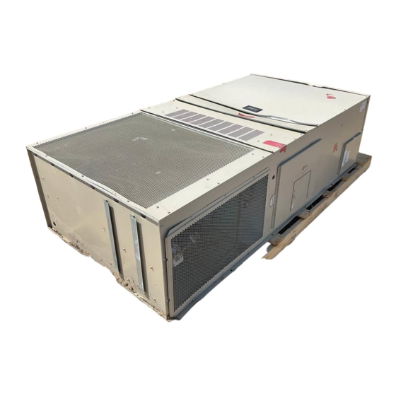
WALL MOUNTED
PACKAGED
AIR CONDITIONER
Models:
H42A2
H48A2
H60A2
MIS-2498
Manual :
Supersedes:
File:
Date:
H42L2
H48L2
H60L2
2100-585A
2100-585
Volume III Tab 16
03-05-14
Manual
2100-585A
Page
1 of 19
Advertisement
Table of Contents

Related Manuals for Bard H42A2


Summary of Contents for Bard H42A2
- Page 1 PACKAGED AIR CONDITIONER INSTALLATION Models: INSTRUCTIONS H42A2 H42L2 H48A2 H48L2 H60A2 H60L2 MIS-2498 Bard Manufacturing Company, Inc. Manual : 2100-585A Supersedes: 2100-585 Bryan, Ohio 43506 File: Volume III Tab 16 Since 1914...Moving ahead just as planned. Date: 03-05-14 Manual 2100-585A...
-
Page 2: Table Of Contents
CONTENTS Start Up Getting Other Information and Publications General .............. 13 Topping Off System Charge ........13 Wall Mount General Information Safety Practices ............13 Wall Mount Model Nomenclature ......4 Important Installer Note ........... 13 Shipping Damage ............. 4 High Pressure Switch .......... -
Page 3: Getting Other Information And Publications
GETTING OTHER INFORMATION AND PUBLICATIONS FOR MORE INFORMATION, CONTACT These publications can help you install the air conditioner or heat pump. You can usually find these THESE PUBLISHERS: at your local library or purchase them directly from the publisher. Be sure to consult current edition of each ACCA Air Conditioning Contractors of America standard. -
Page 4: Wall Mount General Information
WALL MOUNT GENERAL INFORMATION AIR CONDITIONER WALL MOUNT MODEL NOMENCLATURE – CONTROL MODULES REVISIONS MODEL NUMBER (See Spec. Sheet) CAPACITY 42 - 3½ Ton VOLTS & PHASE COIL OPTIONS 48 - 4 Ton A - 230/208/60/1 X - Standard COLOR OPTIONS 60 - 5 Ton 1 - Phenolic Coated Evaporator X - Beige (Standard) -
Page 5: Duct Work
5/8 inch. Any grille that meets with 5/8 inch louver criteria may be used. It is recommended that Bard Return Air Grille Kit RG5 or RFG5 be installed when no return duct is used. -
Page 6: Installation Instructions
INSTALLATION INSTRUCTIONS WALL MOUNTING INFORMATION WARNING 1. Two holes for the supply and return air openings must be cut through the wall as shown in Figure 2. 2. On wood frame walls, the wall construction must be Failure to provide the 1/4 inch clearance strong and rigid enough to carry the weight of the between the supply duct and a combustible unit without transmitting any unit vibration. -
Page 7: Figure 1 Unit Dimensions
Note 1: When security fences, theft guards, or other objects restrict use of the standard 100% air intake hood the alternate 3" air intake hood Bard Part Number WMDK5- (color) may be ordered; however, it will result in only 75% of cooling rated airflow in the full open position instead... -
Page 8: Figure 2 Mounting Instructions - H42, 48, 60
Manual 2100-585A Page 8 of 19... -
Page 9: Figure 3 Electric Heat Clearance
FIGURE 3 ELECTRIC HEAT CLEARANCE H42A2, H42L2, H48A2, H48L2, H60A2, H60L2 NOTE 1: SIDE SECTION VIEW OF SUPPLY AIR DUCT FOR WALL MOUNTED UNIT SHOWING 1/4 INCH CLEARANCE TO COMBUSTIBLE SURFACES. WARNING A minimum of 1/4 inch clearance must be maintained between the supply air duct and combustible materials. -
Page 10: Figure 4 Wall Mounting Instructions
FIGURE 4 WALL MOUNTING INSTRUCTIONS WALL STRUCTURE SEE FIGURE 3 – MOUNTING INSTRUCTIONS FACTORY SUPPLIED RAIN FLASHING. MOUNT ON UNIT BEFORE INSTALLATION SUPPLY AIR SUPPLY AIR SUPPLY AIR DUCT OPENING OPENING RETURN AIR RETURN AIR RETURN AIR OPENING OPENING OPENING BOTTOM MOUNTING WOOD OR STEEL SIDING BRACKET. -
Page 11: Figure 6 Common Wall Mounting Installations
FIGURE 6 COMMON WALL MOUNTING INSTALLATIONS SUPPLY DUCT MAY BE LOCATED IN AN ATTIC OR BELOW CEILING RAFTERS AS SHOWN RAIN RAIN FLASHING RAFTERS FLASHING RAFTERS FINISHED CEILING SURFACE SUPPLY AIR DUCT SUPPLY AIR DUCT FINISHED CEILING SURFACE W/ GRILLE RETURN AIR RETURN AIR OPENING W/ GRILLE... -
Page 12: Wiring - Main Power
WIRING – MAIN POWER “6” Used with MD4000 only; do not use for anything else! “Y1” & “7” Used with ECONWMT Economizer; do Refer to the unit rating plate for wire sizing information not use for anything else! and maximum fuse or “HACR” type circuit breaker size. “8”... -
Page 13: Start Up
TOPPING OFF SYSTEM CHARGE 10. Never trap liquid R-410A in manifold sets, gauge lines or cylinders. R-410A expands significantly If a leak has occurred in the system, Bard at warmer temperatures. Once a cylinder or line is Manufacturing recommends reclaiming, evacuating... -
Page 14: Condenser Fan Operation
START UP (Continued) High Pressure Switch and Lockout Sequence CONDENSER FAN OPERATION If the high pressure switch opens, the compressor Applies to H42, H48 and H60 models only. NOTE: contactor will de-energize immediately. The lockout timer Certain models may be equipped with a Low Ambient will go into a soft lockout and stay in soft lockout until Control (LAC), and if so equipped the condenser fan the high pressure switch closes and the delay on break... -
Page 15: Figure 7 Fan Blade Setting
6. Service motor/fan as needed. 7. Reverse steps to reinstall. TABLE 1 FAN BLADE DIMENSION Dimension Model H42A2 / H42L2 H48A2 / H48L2 1.75" H60A2 / H60L2 Manual 2100-585A Page 15 of 19... -
Page 16: Table 2 Cooling Pressure
TABLE 2 COOLING PRESSURE TABLE Air Temperature Entering Outdoor Coil °F Return Air Temp Model Pressure (DB/WB) 75° DB Low Side 62° WB High Side 80° DB Low Side H42A/L 67° WB High Side 85° DB Low Side 72° WB High Side 75°... -
Page 17: Table 3 Electrical Specifications H**A, H**L
Ampacity Ckt. Brkr. Size Ckt. A Ckt. B Ckt. A Ckt. B Ckt. A Ckt. B Ckt. A Ckt. B H42A2-A00, A0Z H42L2 230/208-1 1 or 2 H48A2-A00, A0Z H48L2 230/208-1 1 or 2 H60A2-A00, A0Z H60L2 230/208-1 1 or 2 j Maximum size of the time delay fuse or HACR type circuit breaker for protection of field wiring conductors. -
Page 18: Table 4 Recommended Airflow
TABLE 4 RECOMMENDED AIRFLOW Rated Rated Recommended Factory Speed Model CFM * ESP * Airflow Range Connection H42A, H42L 1400 1600 - 1150 High H48A, H48L 1550 1750 - 1285 High H60A, H60L 1700 1950 - 1375 High * Rated CFM and ESP on high speed tap. TABLE 5 INDOOR BLOWER PERFORMANCE H42/48... -
Page 19: Table 7 Optional Accessories
TABLE 7 OPTIONAL ACCESSORIES EHWA05-A05 EHWA05-A10 EHWA05-A15 WMCB-08A TABLE 8 VENT & CONTROL OPTIONS Factory Installed Field Installed Option Number Part Number CMC-15 Start Kit (230V 1-Phase) BOP-5 Blank Off Plate ECONWMT-T5* 100% Economizer Temperature ECONWMT-E5* 100% Economizer Enthalpy 100% Economizer DC Temperature 100% Economizer DC Enthalpy Manual 2100-585A Page...