Table of Contents
Advertisement
Advertisement
Table of Contents

Related Manuals for Bard HA4S3


Summary of Contents for Bard HA4S3
-
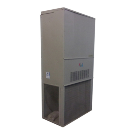
Page 1: Wall Mounted
WALL MOUNTED PACKAGED AIR CONDITIONER INSTALLATION Models: INSTRUCTIONS HA4S3 HL4S2 HA5S3 HL5S2 Bard Manufacturing Company, Inc. Manual : 2100-573A Supersedes: 2100-573 Bryan, Ohio 43506 File: Volume III Tab 16 Since 1914...Moving ahead just as planned. Date: 07-09-12 Manual 2100-573A Page... -
Page 2: Table Of Contents
CONTENTS Start Up Getting Other Information and Publications General ............. 13 For more information contact these publishers ..3 Topping Off System Charge ........13 Wall Mount General Information Safety Practices ............. 13 Air Conditioner Wall Mount Model Nomenclature ..4 Important Installer Note ......... -
Page 3: Getting Other Information And Publications
Getting Other Information and Publications FOR MORE INFORMATION, CONTACT These publications can help you install the air conditioner or heat pump. You can usually find these at your local THESE PUBLISHERS: library or purchase them directly from the publisher. Be sure to consult current edition of each standard. -
Page 4: Wall Mount General Information
WALL MOUNT GENERAL INFORMATION AIR CONDITIONER WALL MOUNT MODEL NOMENCLATURE MODEL CONTROL MODULES REVISION NUMBER J – Only HA – Right Hand HL – Left Hand K – Accumulator COIL OPTIONS X – Standard 1 - Phenolic Coated Evaporator VOLTS & PHASE 2 - Phenolic Coated Condenser A –... -
Page 5: Figure 1 Unit Dimensions
TABLE 2 DIMENSIONS OF BASIC UNIT FOR ARCHITECTURAL & INSTALLATION REQUIREMENTS (NOMINAL) All dimensions in inches. Dimensional Drawings are not to scale. FIGURE 1 — UNIT DIMENSIONS HA*S* RIGHT Built In Rain Hood UNIT 4° Pitch Heater 2.13 Access Panel Side Wall Supply Air Opening Mounting... -
Page 6: Table 3 Electrical Specifications
Manual 2100-573A Page 6 of 21... -
Page 7: Shipping Damage
Any grille that meets the 5/8 inch louver criteria, may be and/or local codes in any way. Authorities having used. It is recommended that Bard Return Air Grille Kit jurisdiction should be consulted before the installation is RG-5 or RFG-5 be installed when no return duct is used. -
Page 8: Installation Instructions
INSTALLATION INSTRUCTIONS WALL MOUNTING INFORMATION 3. Locate and mark lag bolt locations and bottom mounting bracket location. See Figure 4. 1. Two holes, for the supply and return air openings, 4. Mount bottom mounting bracket. must be cut through the wall as shown in Figure 3. 5. -
Page 9: Figure 2 Mounting Instructions
The unit rating plate lists a “Maximum Time Delay To convert for the locking capability, bend the tab Relay Fuse” or “HACR” type circuit breaker that is to located in the bottom left hand corner of the disconnect be used with the equipment. The correct size must be opening under the disconnect access panel straight out. -
Page 10: Figure 3 Wall-Mounting Instructions
FIGURE 3 WALL-MOUNTING INSTRUCTIONS SEE FIGURE 3 — MOUNTING INSTRUCTIONS WALL STRUCTURE FACTORY SUPPLIED RAIN FLASHING. MOUNT ON UNIT BEFORE INSTALLATION SUPPLY AIR SUPPLY AIR SUPPLY AIR DUCT OPENING OPENING RETURN AIR RETURN AIR RETURN AIR OPENING OPENING OPENING BOTTOM MOUNTING WOOD OR STEEL SIDING BRACKET. -
Page 11: Figure 5 Common Wall-Mounting Instructions
FIGURE 5 COMMON WALL-MOUNTING INSTALLATIONS SUPPLY DUCT MAY BE LOCATED IN AN ATTIC OR BELOW CEILING RAFTERS AS SHOWN RAIN RAIN FLASHING RAFTERS FLASHING RAFTERS FINISHED CEILING SURFACE SUPPLY AIR DUCT SUPPLY AIR DUCT FINISHED CEILING SURFACE W/ GRILLE RETURN AIR RETURN AIR OPENING W/ GRILLE OPENING W/ GRILLE... -
Page 12: Wiring - Low Voltage Wiring
WARNING FIGURE 6 ELECTRIC HEAT CLEARANCE • A minimum of 1/4 inch clearance must be maintained between the supply air duct and combustible materials. This is required for the first 3 feet of ducting. • It is important to insure that the 1/4 inch minimum spacing is maintained at all points. -
Page 13: Start Up
Purge with small amount of nitrogen when inserting plugs. TOPPING OFF SYSTEM CHARGE If a leak has occurred in the system, Bard Manufacturing recommends reclaiming, evacuating (see criteria above), and charging to the nameplate charge. Topping off the system charge can be done without problems. -
Page 14: Figure 7 Start-Up Label
START UP CONTINUED IMPORTANT INSTALLER NOTE HIGH & LOW PRESSURE SWITCH For improved start-up performance, wash the indoor coil All models covered by this Manual are supplied with a with a dishwasher detergent. remote reset high pressure switch and low pressure switch. -
Page 15: Service Hints
High Pressure Switch and Lockout Sequence SERVICE HINTS If the high pressure switch opens, the compressor 1. Maintain clean air filters at all times. Also, do not close contactor will de-energize immediately. The lockout off or block supply and return air registers. This reduces timer will go into a soft lockout and stay in soft lockout air flow through the system, which shortens equipment until the high pressure switch closes and the delay on... -
Page 16: Adjustments
Alarm Relay Output MOTOR START DEVICE Alarm terminal is output connection for applications Single Phase (-A) model compressor circuits are where alarm relay is employed. This terminal is equipped with a 25 ohm PTCR (Positive Temperature powered whenever compressor is locked out due to HPC Coefficient Resistor) motor starting device as standard or LPC sequences as described. -
Page 17: Figure 8 Fan Blade Setting
TROUBLESHOOTING COMPRESSOR SOLENOID FAN BLADE SETTING DIMENSIONS Shown in the drawing below are the correct fan blade A nominal 24-volt direct current coil activates the setting dimensions for proper air delivery across the internal compressor solenoid. The input control circuit outdoor coil. -
Page 18: R-410A Refrigerant Charge
TROUBLESHOOTING CONT’D. The following pressure tables show nominal pressures R-410A for the units. Since many installation specific situations can affect the pressure readings, this REFRIGERANT CHARGE information should only be used by certified technicians as a guide for evaluating proper system This unit was charged at the factory with the quantity performance. -
Page 19: Ge Ecm ™ Motors
TROUBLESHOOTING GE ECM MOTORS ™ CAUTION: Symptom Cause/Procedure • Noisy blower or cabinet • Check for loose blower housing, panels, etc. Disconnect power from unit before removing or replacing • High static creating high blower speed? connectors, or servicing motor. To avoid electric shock - Check for air whistling through seams in from the motor’s capacitors, disconnect power and wait at ducts, cabinets or panels... -
Page 20: Figure 9 Control Disassembly
TROUBLESHOOTING GE ECM MOTORS CONT’D. ™ 8b. IF REPLACING AN ECM 2.3 CONTROL WITH AN ECM 2.3 Replacing ECM Control Module CONTROL, the plastic tab and shorter through-bolts are not needed. The To replace the control module for the GE variable-speed indoor blower control can be oriented in two positions 180°... -
Page 21: Optional Accessories
TABLE 6 INDOOR BLOWER PERFORMANCE 1 1 1 1 1 2 2 2 2 2 3 3 3 3 3 4 4 4 4 4 5 5 5 5 5 6 6 6 6 6 1 Motor will deliver consistent CFM through voltage supply range with no deterioration. (197-253V for 230/208V models, 414-506V for 460V models) 2 Continuous CFM is the total air being circulated during continuous (manual) fan mode.