
Related Manuals for Ryobi RA-NBA1564-K


Summary of Contents for Ryobi RA-NBA1564-K
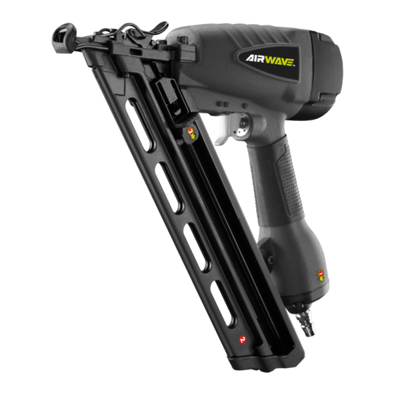
- Page 1 RA-NBA1564-K AIRwAve DA BRAD NAIleR OpeRAtOR's MANUAl ORIgINAl INstRUctIONs Important! It is essential you read the instructions in this manual before starting and operating this machine. Subject to technical modifications.
- Page 2 DescRIptION 1. Nitto style coupler 2. Exhaust cap 3. Air supply 4. Nails 5. Pusher 6. Magazine 7. Trigger 8. Depth adjustment knob 9. Safety yoke Fig. 3 10. Jam release Fig. 1 Fig. 2 Fig. 3 Fig. 4 Fig. 5...
- Page 3 Fig. 6 Fig. 7 Fig. 8 Fig. 9 Quick Quick connector connector Lubricator Filter Tool compressor Cut-off valve Quick Quick coupler coupler Regulator Air hose (0-8.5 bar) Fig. 10...
-
Page 4: General Safety Rules
comfortable posture while maintaining a secure footing geNeRAl sAFety RUles and avoiding awkward or off-balanced postures. The operator should change posture during extended ■ For multiple hazards, read and understand the safety tasks, which can help avoid discomfort and fatigue. instructions before installing, operating, repairing, maintaining, changing accessories on, or working ■... -
Page 5: Information On Mechanical Impact(Vibration)
INFORMAtION ON MechANIcAl IMpAct(vIBRAtION) ■ Repairs shall be carried out only by the manufacturer's authorized agents or by other experts, having due The characteristic vibration values for the fastener driving regard to the information given in the operating tool have been determined in accordance with ISO 8662- instructions. -
Page 6: Residual Risks
trigger using finger pressure. flying objects. In addition, fastener driving tool is fitted with a safety yoke which enables the driving operation to be carried syMBOls out only after the muzzle of the tool is pressed against a work piece, These tools are marked with an inverted triangle behind the serial number and are not Safety alert... -
Page 7: Intended Use
wARNINg Working pressure 5.5 - 8.3 bar (80 - 120 psi) range Ensure the air supply is clean and does not exceed 8.3 bar (120 psi) while operating the product. Too Exhaust Rear adjustable high an air pressure and unclean air will shorten the Tool weight 2.29 kg product's life due to excessive wear, and may be... -
Page 8: Operation
Before connecting the tool, check the air compressor OpeRAtION gauge to be sure it is functioning within the proper range of 5.5 - 8.3 bar (80 - 120 psi). wARNINg ADjUstINg the exhAUst Do not use oxygen, combustible gases or bottled gases See figure 2. - Page 9 wARNINg wARNINg Always use a coupling that discharges all the Use only the fasteners recommended for use with this compressed air in the tool at the time the fitting or tool. The use of any other fasteners can result in tool hose coupling is disconnected.
-
Page 10: Clearing A Jammed Fastener
DRIve Depth ADjUstMeNt 2. Grip the tool firmly to maintain control. Position the safety yoke of the tool onto the work surface. See figure 7. 3. Push the tool against the work surface to depress the The driving depth of the fastener may be adjusted. It safety yoke. -
Page 11: General Maintenance
NOte: Some commercial air line drying liquids are harmful 7. Reconnect the tool to the air supply. to “O” rings and seals. Do not use these low temperature 8. Reinstall fasteners. air dryers without checking compatibility. MAINteNANce AIR sUpply pRessURe AND vOlUMe Air volume is as important as air pressure. - Page 12 lUBRIcAtION automatic in-line filter-regulator-lubricator recommended (Fig. 10) as it increases product life and keeps the product in sustained operation. The in-line lubricator should be regularly checked and filled with air tool oil. Proper adjustment of the in-line lubricator is performed by placing a sheet of paper next to the exhaust ports and actuate the tool 10 - 15 times without fasteners loaded.
-
Page 13: Troubleshooting
tROUBleshOOtINg pROBleM cAUse pOssIBle sOlUtION Loose screws. Tighten screws. Air leak near the top of the tool or in the trigger area. Worn or damaged O-rings or seals. Install overhaul kit. Loose screws. Tighten screws. Air leak near the bottom of the tool. -
Page 14: Parts List
pARts lIst Description Description Description Description Bolt Bumper Trigger valve guide Fixed cover Axle sleeve Cylinder cover washer Spring O-ring 9 x 1.8 Gun body O-ring 2.5 x 1.5 Retainer ring Air deflector Rubber washer Switch valve stem Drive nail slip Bolt M5 x 25 O-ring 1.7 x 2 O-ring 18 x 2.65... - Page 15 techtronic Industries (Australia) pty. ltd. Level 1, 660 Doncaster Road Doncaster, VIC 3108, Australia techtronic Industries New zealand ltd. 18-26 Amelia Earhart Avenue Mangere, Auckland 2022, New Zealand...