Table of Contents
Advertisement
Quick Links
WARNING:
READ THIS
FIRST
This symbol is intended to alert the user to
the presence of important operating and
maintenance (servicing) instructions in the
literature accompanying the appliance.
This symbol is intended to alert the user to
the presence of un-insulated dangerous
voltage within the product's enclosure that
may be of sufficient magnitude to constitute
a risk of electric shock to persons.
IMPORTANT SAFETY INSTRUCTIONS
Use in countries other than the U.S.A. may require the use of a different
line cord or attachment plug, or both. To reduce the risk of fire or
electric shock, refer servicing to qualified service personnel. To reduce
risk of fire or electric shock do not expose this product to rain or mois-
ture.
GROUNDING INSTRUCTIONS
This product must be grounded. If it should malfunction or break down,
grounding provides a path of least resistance for electric current, reduc-
ing the risk of electric shock. This product is equipped with a cord
having an equipment-grounding conductor and a grounding plug. The
plug must be plugged into an appropriate outlet properly installed and
grounded in accordance with all local codes and ordinances.
DANGER
Improper connection of equipment grounding conductor can result in
the risk of electric shock. Check with a qualified electrician or service
personnel if you are in doubt as to whether the product is properly
grounded. Do not modify the plug provided with this product. If it will
not fit the outlet, have a proper outlet installed by a qualified technician.
CAUTION
If the 6200, ESI-32 is rack mounted, a standard 19 inch open frame rack
must be used.
USER-MAINTENANCE INSTRUCTIONS
1. The ESI-32 should be kept clean and dust free. Periodically wipe the
unit with a clean, lint free cloth. Do not use solvents or cleaners.
2. There are no user lubrication or adjustment requirements.
3. Refer all other servicing to qualified service personnel.
INSTRUCTIONS PERTAINING TO A RISK OF FIRE, ELECTRIC
SHOCK, OR INJURY TO PERSONS
WARNING; When using electric products, basic precautions should
always be followed, including the following:
1. Read all instructions before using the ESI-32.
2. To reduce the risk of injury, close supervision is necessary when the
ESI-32 is used near children.
3. Do not use the ESI-32 near water — for example near a bathtub,
washbowl, kitchen sink, in a wet basement, on a wet bar, or near or
in a swimming pool.
4. The ESI-32 should be situated so that its location or position does
not interfere with its proper ventilation.
5. The ESI-32 should be located away from heat sources such as
radiators, heat registers, fireplaces, stoves, or ovens.
i
Contents
Advertisement
Table of Contents

Related Manuals for E-Mu ESI-32


Summary of Contents for E-Mu ESI-32
- Page 1 CAUTION If the 6200, ESI-32 is rack mounted, a standard 19 inch open frame rack This symbol is intended to alert the user to must be used.
- Page 2 6. The ESI-32 should only be connected to a power supply of the type described in the operating instructions and as marked on the product. 7. Care should be taken so that objects do not fall and liquids are not spilled into the enclosure of the ESI-32 through openings.
- Page 3 • Turn the television or radio antenna until the interference stops. • Move the ESI-32 to one side or the other of the television or radio. • Move the ESI-32 farther away from the television or radio. • Plug the ESI-32 into an outlet on a different circuit than the television or radio.
- Page 4 ESI-32 Operation Manual...
-
Page 5: Table Of Contents
Contents General Instructions Introduction ..................3 The ESI-32.................... 4 Connection Instructions ............... 6 Connection Diagram ................7 Connecting to an Unformatted Hard Disk ..........9 Sampling Basics .................. 10 Definitions ..................11 Additional Definitions................. 15 Controls Master Volume ..................21 Data Entry Control ................ - Page 6 3. MIDI Load Bank ..............81 4. MIDI Volume Pedal ............81 5. MIDI Volume/Pan ............... 82 6. Multimode Enable .............. 82 0. Import Options ................83 0. Akai Import................ 83 1. Emax II Import ..............89 ESI-32 Operation Manual...
- Page 7 Sample Management 0. Select Sample .................. 95 1. Load Sample ................... 95 2. Rename Sample ................96 3. Erase Sample .................. 97 4. Copy Sample .................. 98 5. Setup ....................99 6. Place Sample ................. 101 7. Arm Sampling ................102 8.
- Page 8 Using SCSI ..................201 Disk Drive Compatibility Chart ............205 Digital Interface ................206 Keyboard Character Chart ..............207 ESI-32 Menu Map ................208 MIDI Key Numbers ................209 MIDI Implementation Chart ............. 210 Specifications ..................211 Error Codes ..................212 Troubleshooting ................
-
Page 9: General Instructions
General Instructions Introduction ......3 The ESI-32 ....... 4 Connection Instructions ..8 Connection Diagram ....7 Connecting to a Hard Disk ..9 Sampling Basics ..... 10 Definitions ......11 Additional Definitions ... 15 Intro/Basic Setup... - Page 10 ESI-32 Operation Manual...
-
Page 11: Introduction
Introduction Welcome to the ESI-32 Digital Sampling System. Congratulations are definitely in order! The many functions of the ESI-32 are detailed in this manual by their module. Screen displays and step-by-step instructions are described for all aspects of use and operation. Sidebars are used to highlight important points or to give useful operational tips which might not be readily apparent. -
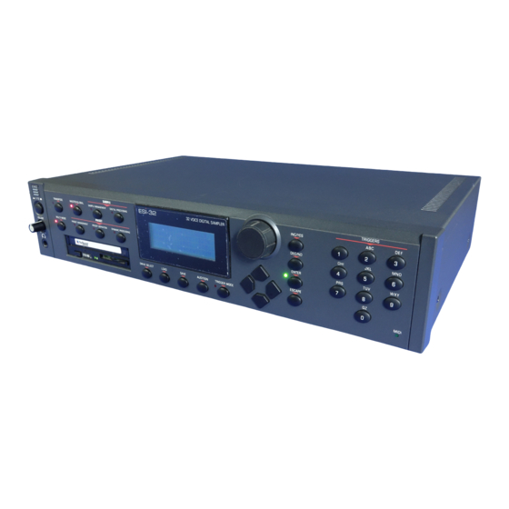
Page 12: The Esi-32
TRIGGER MODE MIDI The ESI-32 The ESI-32 is the latest in the long line of high quality and affordable E-mu sampling products. The ESI-32 features 22.05 kHz and 44.1 kHz sampling rates and 16-bit resolution for CD quality sound. Sampling can be performed in either mono or true stereo. - Page 13 The ESI-32 can access up to 999 samples per bank arranged in up to 256 presets. The integral 3.5" floppy disk drive provides a convenient means of storing and loading banks.
-
Page 14: Connection Instructions
Connecting to a Mixer Main Outputs: The ESI-32 has provisions for a variety of output con- nection schemes. The most common hookup will probably be using the main stereo outputs. Output level is -10 dBm (approximately 1-2 volts RMS). Output impedance is 1K ohm. -
Page 15: Connection Diagram
Connection Diagram To Digital Mixer, DAT, etc. Computer Digital Effect Device 60 mS SCSI Device Digital Input Device DAT Recorder, etc. SCSI MIDI In Power Cord Other Submix Out/Mix In Sampler MIDI Out Mic or Line Inputs Mixer MIDI Controller MIDI In MIDI In (MIDI Keyboard, Sequencer, etc.) - Page 16 110V / 220V Operation The ESI-32 may be used in either 110 volt or 220 volt environments at either 50 Hz or 60 Hz. No change of voltage settings is required. The ESI-32 automatically switches itself for 110 or 220 volt operation.
-
Page 17: Connecting To An Unformatted Hard Disk
ESI-32 to a SCSI device. Connecting the ESI-32 to an External, Unformatted Hard Disk 1. Position the SCSI device and the ESI-32 in a stable location. Hard disk drives are particularly susceptible to shock and vibration. Make sure that you position your hard disk where it won't be bumped or moved while in use. -
Page 18: Sampling Basics
The ESI-32 is conceptually like a tape recorder. However, the recording process is very different since the ESI-32 digitally records into its com- puter memory. Sounds for the ESI-32 can be loaded via removable- media hard disk, magneto-optical disk, CD-ROM using the SCSI interface;... -
Page 19: Definitions
You can think of the ESI-32 as resembling a collection of sound-organiz- ing modules, all contained within an the ESI-32 bank. Pathways indicate how information flows within the ESI-32. Let’ s take a closer look at what makes up this information, and how it is transferred from one section of the instrument to another. - Page 20 As an example, suppose you wanted to set the velocity response for the entire keyboard. You would first select the zone range by playing the lowest and highest keys when prompted by the ESI-32. Next you would set the velocity response (in the Dynamic Processing module). Done.
- Page 21 Loop Points Loop Points Loop Points THE BANK All the data loaded into the ESI-32 is called the Bank. Each individual keyboard setup is called a Preset. Individual Samples can be shared among presets. The Internal Drive A disk drive is a memory storage device that stores banks of data. The standard ESI-32 has a built-in floppy disk drive which can be used to load and store bank data.
- Page 22 ESI-32. Here are some of the can load hard disk data created on the EIII, EIIIX, Emax II or the Akai S1000/S1100. types of mass storage devices that can plug into the ESI-32’ s SCSI connector. •...
-
Page 23: Additional Definitions
You can always hear the current sample by pressing the audition button or entering the Digital Processing module. Modules A module controls a particular set of functions in the ESI-32. There are six main modules: Master/Global, Preset Management, Preset Definition, Sample Management, Digital Processing and Dynamic Processing. - Page 24 Saving The bank only retains data for as long as the ESI-32 is plugged in and turned on. Of course, we don’t expect you to leave the thing on all the time, which brings us to the subject of saving data.
- Page 25 By specifying one or more of these samples (or portions thereof) as a zone, the zone may then be processed by the ESI-32’ s dynamic signal processors. •...
- Page 26 ESI-32 Operation Manual...
- Page 27 Controls Master Volume ....... 21 Data Entry Control ....21 Inc/Dec Buttons ..... 21 Ten Key Pad ......21 Escape ........21 Enter ........21 Cursor/Page ......22 Preset Selection ...... 22 Save Bank ....... 23 Load Bank ......23 Drive Select ......
- Page 28 ESI-32 Operation Manual...
-
Page 29: Controls
A flashing Enter LED means that the ESI-32 wants you to do something. Data may need to be entered, or the ESI-32 may be waiting for you to press the Enter button to activate a particular operation. If the Enter LED is lit steadily, pressing Enter is optional. -
Page 30: Cursor/Page
Tip: The cursor buttons can be used to placed under the preset number, presets may be incremented or select presets only when the ESI-32 is in decremented by pressing the left and right cursor buttons. This Omni or Poly modes. -
Page 31: Save Bank
1. Press Save. 2. If necessary, select the drive to which the bank will be saved. The ESI-32 will default to the current drive. If you want to choose a different drive, place the cursor under the drive number in line two, select the appropriate drive and press ENTER. -
Page 32: Drive Select
This allows the ESI-32 to be used as a stand-alone sample playback unit .In Trigger Mode, the LED next to the button illuminates and all ESI-32 functions operate normally, except that the ten key pad is now used exclusively for triggering sounds. -
Page 33: Multimode
This function transposes the entire ESI-32 in half-step intervals up to ± one octave. When in multimode, all channels will be transposed. When the ESI-32 is in Transpose mode, the Transpose LED will be lit steadily. A new transposition can be selected at any time, regardless of whether or not the Transpose LED is lit. - Page 34 3. While holding Transpose, check the display to confirm the transposition interval. Upward transpositions are indicated with a + symbol, downward transpositions with a - symbol. For example, if the ESI-32 is transposed up a fifth, the display will show: TRANSPOSE Play a Key 4.
- Page 35 Guided Tours 1. Basics ......... 29 2. Current Sample & Zone ..33 3. Dynamic Processing ... 35 4. Realtime Controls ....42 5. Sampling ......45 6. Digital Processing ....47 7. Managing the Bank .... 54 8. On Your Own ..... 54 Guided Tours...
- Page 36 ESI-32 Operation Manual...
-
Page 37: Guided Tours
Tour 1 Welcome to the Guided Tours! If you have just met the ESI-32 for the first time, we suggest that you follow these tours until you complete the Guided Tours section. This will get you up and running on the ESI-32 in the fastest possible time. - Page 38 In preparation, you must have at least five double- sided, high-density, 3.5" diskettes on hand. Before a floppy disk can be used by the ESI-32, it must be formatted using the Format Disk func- tion. To Format a Floppy Disk: 1.
- Page 39 To Format a Hard Disk Drive Like a floppy disk, a hard disk must also be formatted before it can be used to store information. 1. Activate the Master/Global module. 2. Select 7. Disk Utilities, 7. Format Disk (7/6). 3. Select the hard disk using the data entry control and press ENTER.
- Page 40 Tuning the ESI-32 to Other Instruments Refer to the Master/Globals module, 1. Master Tune. This function demonstrates how the ESI-32 uses the data entry control to adjust a parameter. Play the keyboard while adjusting the data entry control to change the overall tuning.
-
Page 41: Tour 2: The Current Sample & Current Zone
Tour 2 The ESI-32 has two modules dedicated exclusively to processing samples within a preset: Sample Management and Digital Processing. Each sample stored in a bank can be processed by the Digital Processing module independently. Therefore, we need a way to specify the current The Current sample, which is the individual sample to be processed. - Page 42 3 . S e l e c t a S u b m o d u l e & M o d i f y Z o n e Any range of the keyboard can be a zone. Select the low and high keys which define the zone, then select the Dynamic Processing parameter to be modified. ESI-32 Operation Manual...
-
Page 43: Tour 3: Dynamic Processing
A filter is a device which allows you to remove certain components of a sound depending on its frequency. For example, a Low Pass Filter, like the one in ESI-32, lets the low frequencies pass and removes only the high frequencies. - Page 44 2. Move the cursor back to Cutoff on line three. Vary the data entry control. Note how this produces a sort of wa-wa effect. Remember, you have to re-trigger the key to hear the results of changing the Q. ESI-32 Operation Manual...
- Page 45 3. Set Cutoff to 200 Hz and Q to about 50. The range of notes covered by the current zone should sound muted. To Change the Filter Cutoff Envelope: 1. Select page two by pressing the right cursor arrow. Tracking: +1.00 Envelope Amt: Investigate the effects of envelope control over the filtered sound by...
- Page 46 2. Select the 2. VCA function. The display shows: Strings Level: 100% Pan: + 0% Percussion The generalized envelope shapes of a few types of sounds are shown above. ESI-32 Operation Manual...
- Page 47 3. Select the next page of the VCA controls with the right cursor. VCA Attack: 0.20s Hold: 0.00s Decay: 0.30s Sus:50% Rel:0.60s Move the cursor under the various envelope parameters and observe how different settings affect the sound. Before moving on, make sure you have a sound that is fairly sustained with little or no envelope attack time.
- Page 48 Now play the keyboard. Since we are using an inverted envelope, notes will bend up to pitch and then hold there. This is an effect common in many natural sounds. Vary the various envelope parameters, and observe the effect these changes have on the sound. ESI-32 Operation Manual...
- Page 49 Move the data entry control to select different values, and note the Tip: Remember that the velocity-to- effects. With positive velocity sent to the VCA, the ESI-32 plays softer as envelope Attack setting interacts with the initial envelope Attack settings. Call up the you play softer.
-
Page 50: Tour 4: Realtime Controls
Want to change the pitch bend range? Activate the Preset Definition module, 6. MIDI. Modulation Wheel Destinations The ESI-32 offers two modulation options: Pre-programmed, which adds a constant, selectable amount of modulation, and Realtime, where the player adds in modulation by using one of the wheels or other controllers. - Page 51 For example, if you assigned mod. control to VCF cutoff and then assigned pressure to VCF cutoff, the Footswitch Destinations ESI-32 would automatically turn off the mod. control to VCF cutoff routing. 0: Off 5: Unused 3...
- Page 52 Keeping this in mind, refer to the Preset Definition module, 0. Realtime Controls, footswitch destinations 0-9. (Destinations 3-7 are EIII func- tions which were not implemented in the ESI-32. The numbers were retained to maintain compatibility.) Assign various functions to the footswitches.
-
Page 53: Tour 5: Sampling
200.8 secs Available Check the available sampling time. This will vary depending on how much memory you have in your ESI-32. 5. Change the source using the data entry control for analog sampling. Set the source to either Analog 22050 Hz or Analog 44100 Hz. - Page 54 Speaking into the microphone, you should see the VU meter move, Tip: The optimum gain level setting for indicating that the ESI-32 is receiving signal. Place the cursor on line ESI-32 is +00. For high-quality sampling, one of the display and use the data entry control to adjust the input use an external microphone preamplifier gain.
-
Page 55: Tour 6: Digital Processing
When you are satisfied with your truncating efforts, press ENTER. The ESI-32 will automatically make a backup of the sample on the hard disk, (if you have one connected) in case you decide that you don’t like the truncation after all. -
Page 56: A Practice Sampling Session
G1. 8. Truncate the silence off of the beginning and end of the sound. Activate the Digital Processing module. The ESI-32 will default to the only sample in the unit, which is the one you just made. - Page 57 To loop, first move the data entry control to make the loop length about half a second long. Next, move the start point into the sustained portion of the ahhh sound so that the ticking sound becomes softer. The idea is to loop the “hhh”...
- Page 58 4. Move the cursor under End on line three. Adjust the data entry control so that only the word “cut” is heard. Press ENTER. The display will inform you that the ESI-32 is backing up the sample, and then will return you to the module identifier.
- Page 59 5. Select 6. Paste. The display shows: PASTE secs samples Offset: 0.00 00000 Select Location Adjust the offset past that “tt” sound of the word paste. Again use the left and right cursor keys once you get close. Press ENTER. The sample should now say, “and paste, cut”.
- Page 60 Exponential Curve 2, then press ENTER. The sample should now smoothly fade out instead of ending abruptly. And remember that Digital Processing, 9. Undo will cancel the effects of Taper. You can use this feature to further experiment with different Taper settings. ESI-32 Operation Manual...
- Page 61 The pitch change Type is not critical, but mid-2 seems to work well for voice. Press Enter to begin the pitch change. If you have a hard disk connected, the ESI-32 will automatically back up your sample before processing it. If you don't like the resulting pitch change, press Digital Processing, Undo.
-
Page 62: Tour 7: Managing The Bank
The proceeding guided tours cover only the basics. To cover every possibility of how to use the ESI-32 would drown you in words. It’ s better that you just start playing! The best way to learn the ESI-32 is to Your Own power up and dive right in. - Page 63 Master/Global 1. Master Tune ....... 57 2. Rename Bank ..... 57 3. Erase Bank ......58 4. Dynamic Allocation ... 58 5. Save as EIII Bank ....59 6. Memory Available ....60 7. Disk Utilities ...... 60 0. SCSI Setup ......... 61 1.
- Page 64 ESI-32 Operation Manual...
-
Page 65: Master/Global
4. Select the Transpose amount. Transpose allows you to transpose the ESI-32 without the use of a keyboard. The transpose range is ± one octave. 5. Press ENTER to exit the submodule. The ESI-32 will return to the Module Identifier. 2. Rename This submodule allows you to rename the current bank. -
Page 66: Erase Bank
This function (when on) bypasses the channel assignments made in the Output Channels submodule of the Dynamic Processing module, and allows all of the ESI-32's 32 channels to be assigned in a circular manner Allocation as needed. (Channels are assigned in ascending, circular order as notes are played, i.e. -
Page 67: Save As Eiii Bank
This function allows you to save an ESI-32 bank in the original EIII bank format so that it can be read by an EIII (the EIII is the predecessor of the ESI-32). If the bank you are trying to save exceeds 8 Mb, or has Bank more then 100 presets or 100 samples, you will not be allowed to save as an EIII bank. -
Page 68: Memory Available
This may Sample limit your sample size even though you have plenty of memory left. 4. Press ENTER to exit the submodule. The ESI-32 will return to the Module Identifier. 7. Disk Disk Utilities include several additional numbered subsections. -
Page 69: Scsi Setup
0. SCSI Setup This utility allows you to change the SCSI ID number of the ESI-32 itself (not a connected hard disk) in the event that it conflicts with a device on the SCSI bus having the same ID number. -
Page 70: Mount Drives
This utility instructs the ESI-32 to check the SCSI bus for the presence of SCSI devices. If a SCSI device has been powered up after the ESI-32, it will not appear Tip: Use the “Mount Drives” utility in the list of available devices. The Mount Drives utility tells the ESI-32... -
Page 71: Erase Disk Bank
7. Press Yes to erase the bank or No to cancel the operation. In either case, the ESI-32 will return to the Module Identifier. 4. Lock Bank and Drive If you don’t want to risk curious hands unintentionally erasing a bank or drive, here’... -
Page 72: Disk Status
D1 Selected Drive B00 Current Bank Select a Bank 7. Select whether lock is on or off, then press ENTER. The ESI-32 will return to the Module Identifier. 5. Disk Status This function displays the amount of space that is available on a hard disk drive and if the drive is locked or not. -
Page 73: Format Disk
Formatting a disk will not erase the bank currently in memory. 1. Activate Master/Global module. 2. Select 7. Disk Utilities, 6. Format Disk (7/6). 3. Select the drive to be formatted and press ENTER. The ESI-32 will default to the floppy drive. FORMAT DISK... - Page 74 The ESI-32 contains an internal list of recognized hard disk drives which also contains parameter information designed to optimize the interface between the ESI-32 and the drive. Most new hard disk drives use 1:1 interleave. The Appendix chapter of this manual contains a listing of disk drives that have been tested with the ESI-32.
-
Page 75: Backup
(of the Sony type only). Most optical disks that you buy will already have this low level formatting, but some don't and will not be recognized by the ESI-32. This utility allows you to perform the func- tion. This takes about 25 minutes, so don't do it unless absolutely necessary. - Page 76 22 Dog Barks 8. Select the high bank of the range. 9. Press ENTER when the highest bank in the range has been selected. The following screen will appear: BACKUP D0 Main Drive D1 Removable Media Bank Dest: SameBank ESI-32 Operation Manual...
-
Page 77: Floppy Save In Version 1.04
1.04. This function could be useful if you wanted to presets and samples from floppy disks transfer sounds to an older, non-updated ESI-32. To save a bank in the saved in version 1.04 software. older format, simply insert a blank formatted floppy disk (any version) and press ENTER to save. -
Page 78: Special
• 7. Trigger Buttons: Programs the ten-key pad to trigger keyboard notes without a MIDI keyboard when the ESI-32 is in Trigger Mode. • 8. RAM Test: Tests the CPU and the sample memory and displays any errors. -
Page 79: Recalibrate
Negative values make the display easier to read from below. 1. Activate Master/Global module. 2. Select 8. Special, 2. Contrast (8/2) 3. Select the desired contrast setting. CONTRAST Contrast: Select Contrast 4. Press ENTER to exit the submodule. The ESI-32 will return to the Module Identifier. Master/Global... -
Page 80: Headroom
0 dB to 15 dB in 1 dB increments. HEADROOM Headroom: 10dB Select Headroom 4. Press ENTER to exit the submodule. The ESI-32 will return to the Module Identifier. Each channel played adds +3 dB to the output level. Increase the headroom to prevent clipping. ESI-32 Operation Manual... -
Page 81: Main Output Format
3. Set the Output to the format you are using. 4. Turn AES boost on to increase the level of the digital output. 5. Press ENTER to exit the submodule. The ESI-32 will return to the Module Identifier. 5. Software Version 1. -
Page 82: View Channels
3. Use the left/right cursor buttons to place the cursor under the channel to be disabled. VIEW CHANNEL LEVELS 4. Press Escape to exit the submodule. The ESI-32 will return to the Module Identifier. 7. Trigger Buttons This function lets you assign the ten-key pad buttons to trigger specific notes directly from the ten key pad, whenever trigger mode is selected from the front panel button. -
Page 83: Ram Test
A RAM test should always be performed after you have updated the service for information about updating RAM. amount of sample memory in your ESI-32. The test will verify if the new RAM is working and has been correctly installed. -
Page 84: Midi
9. MIDI This section contains several additional numbered functions. These MIDI global functions act on all presets in the ESI-32. Here are short descriptions of each submodule. More extensive descriptions follow. • 1. MIDI Mix: Allows you to monitor and change the volume and pan settings of all 16 MIDI channels at once. -
Page 85: Midi Mix
1. MIDI Mix The MIDI Mix screen is extremely useful in that it allows you to easily fine tune the volume and pan of each preset. In addition, it allows you to override the output channel setting programmed in the Dynamic Pro- cessing module and route each MIDI channel to the output of your choice. -
Page 86: Midi Globals
MIX C=01 Submix=main Mzzz 111z zzzz zzzz 6. Press ENTER to exit the submodule. The ESI-32 will return to the Module Identifier. 2. MIDI Globals MIDI (Musical Instrument Digital Interface) is a universal interface which allows the exchange of musical information between various electronic instruments. -
Page 87: Continuous Controller Assignment
Refer to the diagram on the following page. Suppose a sequencer is sending out modulation data over MIDI control number 01, and that MIDI Control Source A on the ESI-32 controls the filter cutoff frequency. Selecting 01 for MIDI Control Source A would route the sequencer’ s modulation data to the ESI-32’... - Page 88 (also assigned in the Preset Definition, Realtime Control submodule) such as Sustain, Sample Cross-switch, etc.. This screen allows you to match the ESI-32 to your MIDI controller's footswitch numbers. A few of the standardized MIDI switch numbers are listed below.
-
Page 89: Midi Load Bank
3. MIDI Load Bank This feature allows a MIDI command to load banks from the hard disk. The “Magic Preset” is a preset number which tells the ESI-32 that the next preset change command that it receives over MIDI is the bank number to be loaded. -
Page 90: Midi Volume/Pan
5. MIDI Volume/Pan When this function is turned On, the MIDI continuous controllers 7 and 10 will automatically be routed to volume and pan whenever the ESI-32 is in multimode (Volume and Pan are the standard functions of control- ler number 7 & 10.) and their assignments in the Preset Definition submodule will be ignored. -
Page 91: Import Options
• 0. Akai Import: Allows the ESI-32 to read and convert programs and samples from the Akai S1000 and S1100 samplers. • 1. Emax II Import: Allows the ESI-32 to read and convert presets and samples from the Emax II sampler. - Page 92 An Akai SCSI device is NOT mounted and accessed like a normal the ESI-32 drive ( the load and drive buttons will not access the Akai drive). Instead, it is accessed and operated using the Akai menus. Only one Akai SCSI device can be known to the ESI-32 at any given time.
- Page 93 Combine -L/-R When this option is set to “On”, the ESI-32 will look within an Akai keygroup for left/right samples that can be combined into a single stereo sample. If the first 10 characters of the 12 character sample name match, and the last two characters of the two samples are ‘-L’...
- Page 94 Akai Mini-Glossary Partition = Akai hard disks are divided into partitions of 30, 40, 50, or 60 megabytes, unlike the ESI-32 which sees the hard disk as one continuous area. Volume = An Akai partition can contain up to 128 Volumes. A volume is a collection of programs, equivalent to an ESI-32 bank.
- Page 95 10. Use the inc/dec buttons or the data entry control to select the Program. Press ENTER to load and convert a single program. “All” allows you to load and convert all programs in the volume. Selecting “None” allows you to load samples only. AKAI LOAD from Vol:PIANOS Program:FullGrand...
- Page 96 C. Load the preset volume. The above warning only applies to Akai banks with Samples and Pro- grams stored in different Volumes. 13. Press No to exit the submodule. The ESI-32 will return to the Module Identifier. ESI-32 Operation Manual...
-
Page 97: Emax Ii Import
ESI-32 drive (the load and drive buttons will not access the Emax II drive). Instead, it is accessed and operated using the Emax II import menus. Only one Emax or Akai SCSI device can be known to the ESI-32 at any given time. - Page 98 5. Press 1 to select the Import Options screen. The following screen will appear. When this function is set to YES, the ESI-32 will issue an extra prompt whenever a load operation is about to destroy the current bank. Press ENTER after selecting your choice.
- Page 99 Sample Size • Since samples do not have names in the Emax II, they are imported into the ESI-32 with Sxx appended to the bank name, where xx is the number of the sample. Example: Bosendorf8M_S02. • Bank and preset names retain their names from Emax II.
- Page 100 ESI-32 Operation Manual...
- Page 101 Sample Management 0. Select Sample ..... 95 1. Load Sample ...... 95 2. Rename Sample ....96 3. Erase Sample...... 97 4. Copy Sample ...... 98 5. Sample Setup ..... 99 6. Place Sample ....101 7. Arm Sampling ....102 8.
- Page 102 ESI-32 Operation Manual...
-
Page 103: Sample Management
0. Select This submodule selects a sample for placing on the keyboard, or the sample into which a sound will be recorded. Sample 1. Activate Sample Management module. 2. Select Submodule 0. 3. Select the desired sample and press ENTER. As you scroll through non-empty samples, the display will show the sample number, name, sampling rate, sampling length, how many presets use the sample, and whether the sample is stereo, left, or right. -
Page 104: Rename Sample
You can also use the up cursor to insert spaces and the down cursor to delete spaces. (See Sample Management, 2. Rename Sample.) 9. Press ENTER to exit the submodule. The ESI-32 will return to the Module Identifier. 2. Rename This submodule allows you to rename any sample. -
Page 105: Erase Sample
RENAME SAMPLE 001 Untitled Sample [0-9]/Encoder/Kybd 5. Press ENTER to exit the submodule. The ESI-32 will return to the Module Identifier. 3. Erase Individual samples can be erased from the bank, and newly created samples in memory can be erased using this function. -
Page 106: Copy Sample
You can also use the up cursor to insert spaces and the down cursor to delete spaces. 6. Press ENTER to exit the submodule. The ESI-32 will return to the Module Identifier. -
Page 107: Setup
5. Setup In this submodule, you will prepare the ESI-32 for sampling. Either the analog inputs or the optional digital input can be sampled. 1. Activate Sample module. If you want to sample into the sample number shown on the display, you need do nothing except proceed to the next step. - Page 108 Monitor through while sampling: on • Monitor Through While Sampling: Allows you to monitor through the main outputs while sampling is occurring. 7. Press ENTER to exit the submodule. The ESI-32 will return to the Module Identifier. ESI-32 Operation Manual...
-
Page 109: Place Sample
6. Place Samples in the bank can be placed to cover a particular range of the keyboard. Sample 1. Activate Sample Management module. The display will show the current sample number and name. If this is not the sample you want to place, refer to Sample Management, 0. -
Page 110: Arm Sampling
3. Wait as the signal is sampled. 4. Terminate sampling. This will occur automatically after reaching the end of the sample length (if set in 5. Setup), or if the ESI-32 runs out of memory. To stop sampling manually, press ESCAPE. In any case, the display will return to the Module Identifier. -
Page 111: Midi Sample Dump
Sample Integrity function (Digital Processing, 7-7) may be able to automatically repair them. Otherwise adjust the loop points. The ESI-32 can transmit sample data with a word size of either 14 or 16 bits (Certain instruments such as the SP-1200 require the use of the 14 bit word size). - Page 112 Word Size: 16 Bits Select 14/16 Bits 5. Select a sample to be transmitted and press ENTER. If the selected sample is stereo, the ESI-32 will ask you to select which side is to be transmitted. SAMPLE DUMP Direction: Transmit...
- Page 113 Preset Management 1. Load Preset ...... 107 2. Rename Preset ....108 3. Erase Preset ..... 109 4. Copy Preset ...... 109 5. Create Preset ....110 6. Preset Size ......111 7. Merge Presets ....111 Preset Management...
- Page 114 ESI-32 Operation Manual...
-
Page 115: Preset Management
1. Load A preset, with its samples, can be loaded from the floppy disk, the internal Syquest hard disk or an external storage device. Preset 1. Activate Preset Management module. 2. Select Submodule 1. 3. If you wish to select a different drive, move the cursor to the drive number. -
Page 116: Rename Preset
You can also use the up cursor to insert spaces and the down cursor to delete spaces. (See 2. Rename Preset.) 9. Press ENTER to exit the submodule. The ESI-32 will return to the Module Identifier. 2. Rename This submodule allows you to rename any preset in the ESI-32's current bank. -
Page 117: Erase Preset
3. Erase Individual presets, with or without their samples, can be erased from the bank loaded into the ESI-32 to free up memory space. Preset 1. Activate Preset Management module. 2. Select Submodule 3. 3. Select the preset to be erased, then press ENTER. -
Page 118: Create Preset
You can also use the up cursor to insert spaces and the down cursor to delete spaces. 6. Press ENTER to exit the submodule. The ESI-32 will return to the Module Identifier. 5. Create An empty preset must be initialized by the ESI-32 before it can hold samples. -
Page 119: Preset Size
Preset: if the samples are used in several presets. Sample: 9.2% 1543716 4. Press ENTER to exit the submodule. The ESI-32 will return to the Module Identifier. 7. Merge All This function allows you to load all the presets from any bank on any hard disk into the currently loaded bank. - Page 120 6. Press ENTER to merge the presets. The display will say show the new locations of the presets in the bank, then return you to the Module Identifier. MERGE PRESETS into 025 Empty Preset Select Dest Preset ESI-32 Operation Manual...
- Page 121 Digital Processing Background ......115 0. Select Sample ....121 1. Setup ........ 121 2. Loop ......... 122 3. Truncation ......125 4. Copy Region ....125 5. Cut Region ....... 127 6. Paste Region ..... 128 7. Digital Tools 1 ....131 0.
-
Page 122: Background
After playing to the end of the loop, the ESI-32 will jump back to the beginning of the loop and play through the loop again. This process repeats until you release the key playing back the sample. -
Page 123: Digital Processing
Creating Attack & Decay Characteristics for the Looped Portion One potential problem is that the loop repeats at the same level. This is usually acceptable for sustaining instruments (flute, organ, brass, etc.), but is unacceptable for plucked or struck sounds, which decay over time. - Page 124 Crossfade Looping The ESI-32 fades between the beginning and end of the loop so that as the end fades out, the beginning fades in. This virtually eliminates the clicks and pops that can occur with other types of looping. Source Data faded in &...
- Page 125 Clipboard Data: The clipboard will retain data until replaced by other data to be copied, cut, or backed up. This occurs with several ESI-32 operations where you want to be able to undo an action that doesn’t work out as anticipated. Since clipboard data stays intact when you call up another sample, data can be cut or copied from one sample and pasted to another.
- Page 126 The small x marks the initial position. To move forward through the sound to the next zero crossing, press the right cursor button, as shown in the upper diagram. The ESI-32 will find the first zero crossing on the positive slope after the signal has crossed the designated threshold.
- Page 127 Zero X Threshold (Set at -30 dB) Slope of Wave Ignored -30dB -96dB Selected Slope of Wave Ignored -30dB -96dB Selected Adjust the zero crossing threshold according to the type of wave you are processing. A setting of -96 dB is most sensitive and can be used for finding the start point of a sound. Settings closer to -30 dB are less sensitive and suited for finding zero-crossings in complex waves.
- Page 128 ESI-32 SCRUB WHEEL. Move the wheel slightly to advance slowly through the sound. Move the wheel more to advance quickly through the sound. ESI-32 Operation Manual...
-
Page 129: Select Sample
Stereo 44100 Hz 5 Presets 1.6 secs 4.Press ENTER to exit the submodule. The ESI-32 will return to the Module Identifier. 1. Setup This submodule lets you turn looping on and off,, loop in release on and off and sets various parameters concerning other Digital Processing functions. - Page 130 If auto truncate does not seem to be working well, try adjusting the zero crossing threshold. 6. Press ENTER to exit the submodule. The ESI-32 will return to the Module Identifier. ESI-32 Operation Manual...
-
Page 131: Loop
With Auto Correlation, the ESI-32 looks for loop points near the ones you chose that can be spliced together with minimum discontinuity. Occasionally it will be impossible for either you or the ESI-32 to locate a perfect splice point, but in most cases you’ll find that Auto Correlation, combined with practice and experimentation, can produce very smooth loops. - Page 132 Caution: If there is not enough disk fades in. Instead of butt-splicing the end of the loop back to the memory to back up a sample, the ESI-32 will beginning when forward looping, (or butt-splicing the loop end and not let you Crossfade unless you disable the...
-
Page 133: Truncation
3. Truncation Truncation shortens a sample's length by trimming off individual samples from the beginning and/or end. Truncation is most often used to remove unneeded portions of a sample to conserve memory, but it can also be used to change instrument characteristics such as removing the attack from a plucked string note or isolating a particular section of a sample. - Page 134 Copying does not affect the original sample. The clipboard will retain this data until replaced by something else to be copied, cut, or backed up. COPY secs samples Start: 0.00 00001 End: 1.61 57881 Size: 1.61 57881 ESI-32 Operation Manual...
-
Page 135: Cut Region
5. Cut Portions of a sample can be cut, copied, and pasted to other samples, or the samples from which they came. The Cut function removes a section of a sample, and stores the cut portion in a special part of memory called Region the clipboard. -
Page 136: Paste Region
ENTER. waveform. PASTE REGION into S00 Selected Sample Select Dest Sample 4. Specify the paste point on line two as an offset (in samples) relative to the beginning of the sample, then press ENTER. ESI-32 Operation Manual... - Page 137 PASTE secs samples Offset 0.00 000001 Select Location 5. Choose whether to insert or mix the clipboard contents at the point selected in step three, then press ENTER. PASTE secs samples Tip: Use the Copy Sample function Offset 1.06 33943 (Sample Management, 5) to paste the clipboard contents to an empty sample Mode:...
- Page 138 Source Amount: 100% Crossfade Size XFADE MIX Source Amount: 50% 8. Press ENTER to perform the paste. 9. If you are not satisfied with the paste, or want to compare before and after, proceed to Digital Processing, 9. Undo. ESI-32 Operation Manual...
-
Page 139: Digital Tools I
7. Digital This submodule contains several additional numbered functions. These are extremely useful utilities for manipulating samples. The following is a short description of each function. Tools I 0. Sample Calculator: Calculates and displays the optimum pitch to sample rate ratios for single cycle loops at the desired pitch. 1. -
Page 140: Taper
Tip: The left and right cursor buttons Start: 0.00 000000 will change the start and end points so that they fall on positive zero-crossing points in End: 3.13 137873 the waveform. Size: 3.13 137873 TAPER Start Amount: 0.00dB End Amount: -96dB Type: Linear ESI-32 Operation Manual... -
Page 141: Gain Change
5. Move the cursor to the parameter to be selected, select the Caution: When using Taper Gain, avoid clipping the signal with too much gain. The desired value(s) with the data entry control and press ENTER. Normalize display in the Gain Change The sample will be tapered between the selected start and end points submodule can be used as a sample with the type of curve selected. - Page 142 137873 The display will show the current gain change points, which will be the end points of the current sample. After pressing ENTER, the ESI-32 will compute the amount of gain change necessary to achieve normalization or 0 dB headroom.
-
Page 143: Reverse Section
3. Reverse Section Reverses all or part of a sample. 1. Activate Digital Processing module. 2. Select 7, Digital Tools I, 3. Reverse Section (7/3). 3. If the current sample is stereo, the following screen will appear. Select the left side, right side, or both sides (stereo), then press ENTER. -
Page 144: Left <-> Right
Removes the DC component from a sample, centering the waveform around the zero axis. 1. Activate Digital Processing module. 2. Select 7. Digital Tools I, 6. DC Filter (7/6). The ESI-32 will immediately begin scanning the current sample for DC offset. DC FILTER Scanning... -
Page 145: Sample Integrity
2. Select 7. Digital Tools I, 7. Sample Integrity (7/7). The display shows: FIX SAMPLES Fix all samples? Y/N 3. Press ENTER to fix samples in the bank. The ESI-32 will only modify loops which are in need of repair. Digital Processing... -
Page 146: Digital Tools Ii
7. Doppler/Pan: This unique function allows you to dramatically move a sound from front to back and side to side in a 2-D space. Several pre-computed paths as well as 10 user-definable paths are available. ESI-32 Operation Manual... -
Page 147: Sample Rate Convert
0. Sample Rate Convert Sampling at a high sample rate provides better frequency response than sampling at a slower rate, but uses up more memory. If you need to reclaim some of that memory, and are willing to trade off sample fre- quency response, samples can be converted from a higher rate to a lower one. -
Page 148: Digital Tuning
DIGITAL TUNING Tuning: +1200 cents Size: 209882 Loop Size: 69930.00 4. If you are not satisfied with the resulting re-tuning, or want to compare before and after, proceed to Digital Processing, 9. Undo. ESI-32 Operation Manual... -
Page 149: Compressor
2. Compressor The Digital Compressor is a digital (non-realtime) equivalent of an analog dynamic range compressor with attack and release times, adjust- able threshold, adjustable ratio, and three modes of operation. 1. Activate Digital Processing module. 2. Select 8. Digital Tools II, 2. Digital Compressor (8/2). 3. - Page 150 Determines how quickly the gain will be turned down. The attack time is variable from 0 to 999 milliseconds. Release Time Determines how quickly the gain will be turned up. The release time is variable from 0 to 999 milliseconds. ESI-32 Operation Manual...
- Page 151 100% Only signal levels ABOVE the Threshold % will be affected 10:1 Threshold by the compressor. Above 100% Signal levels ABOVE as well as BELOW the Threshold % 10:1 Threshold will be affected by the com- pressor. Center 100% Only signal levels BELOW the Threshold Threshold % will be affected 10:1...
- Page 152 Noise reduction will reduce low levels even further in the assumption that low levels are noise. Set the controls as follows: Threshold: Below, approx. 30% Ratio: approximately 0.7:1 Attack Time: approximately 100 mS Release Time: approximately 100 mS ESI-32 Operation Manual...
-
Page 153: Parametric Equalizer
3. Parametric Equalizer Parametric EQ allows you adjust the individual parameters of the filter. Boost and Cut controls “how much” of the signal will be boosted or cut. Center Frequency sets the center frequency to be boosted or cut, and the Bandwidth control sets the width of the band to be boosted or cut. -
Page 154: Time Compression
Inharmonic or broadband material noisy Non-pitched - Sound Effects, etc. 5. If you are not satisfied with the resulting Time Compression or want to compare before and after, proceed to Digital Processing, 9. Undo. ESI-32 Operation Manual... -
Page 155: Pitch Change
5. Pitch Change This function is the exact opposite of Time Compression in that it changes the pitch of a sample without changing the time. The maximum amount of pitch change is ±1200 cents (± one octave). 1. Activate Digital Processing module. 2. -
Page 156: Transform Multiplication
Digital Processing, 9. Undo. Note Transform Multiplication needs extra memory to perform its thousands of calculations. If you get a memory error, load just the two samples into the ESI and try again. ESI-32 Operation Manual... -
Page 157: Doppler/Pan
7. Doppler/Pan This function allows you to apply either a pre-programmed or user- definable sound path to a mono sample or the left side of a stereo sample. The result is a stereo sample with pitch shifted and left-right gains adjusted according to the path. The sound can move dramatically forward-back and left-right in a 2-D space in front of the listener. - Page 158 9. Press ENTER to begin processing the sample. The display shows: DOPPLER/PAN Processing path... 10. If you are not satisfied with the resulting Doppler/Pan or want to compare before and after, proceed to Digital Processing, 9. Undo. ESI-32 Operation Manual...
- Page 159 PATH MANAGEMENT SCREEN Sound paths may optionally be edited and processed in a number of ways. If the right cursor is pressed in the initial Doppler/Pan screen, the Path Manager screen appears: PATH MANAGER Path: user path 1 Function: reverse The path may be selected in this screen as well.
- Page 160 OFFSET PATH Tip: The “X” offset varies the L-R X offset: +265 position. The “Y” offset varies the front-back position. Y offset: Enter X offset Press ENTER to add the offsets to the path. ESI-32 Operation Manual...
- Page 161 Clear Path This function clears all x,y and time values to zero. If this “zero” path were used to process a sample, the sound would not move. When Clear Path is selected, the following screen will appear: CLEAR PATH Clearing path: user path 2 Are You Sure? Y/N Press YES to clear the path.
- Page 162 Management screen. When the path is ready to apply to the sample, press the left cursor button while in the Path Management screen to return to the main Doppler/Pan screen. Press ENTER again to move ahead to the Path Parameters screen and once more to process the sample. ESI-32 Operation Manual...
-
Page 163: Undo
Other- wise, press ENTER. The original sample will be restored, the processed sample will be stored in the clipboard, and the ESI-32 will return to the Module Identifier. - Page 164 2. Select Submodule 9. REDO TRUNCATION Selected Sample Backup: disabled The display will show whether backup is currently enabled or not. 3. Use the Increment/Decrement buttons to choose whether the backup function is enabled or disabled, then press ENTER. ESI-32 Operation Manual...
- Page 165 Preset Definition 0. Realtime Controls ....159 1. Load Zone ........ 164 2. Edit Assignment ....... 167 3. Erase Zone ....... 170 4. Copy Zone ........ 171 5. Crossfade/Switch ..... 174 6. Velocity Switch/Preset Link ..177 7. Pitch Bend Range ..... 177 8.
- Page 166 ESI-32 Operation Manual...
-
Page 167: Preset Definition
For example, in order to have the pitch wheel of your keyboard control the pitch of the ESI-32, it must be assigned to pitch. Set the Pitch Control to be the source and the pitch as the destination. To make the right wheel control the amount of vibrato (LFO to pitch), set Mod Control as the source and LFO->... - Page 168 2. Mod Control you assigned mod. control to VCF cutoff and then assigned pressure to VCF cutoff, the 3. Pressure Control ESI-32 would automatically turn off the mod. 4. Pedal Control control to VCF cutoff routing. 5. MIDI A Control 6.
- Page 169 (such as during fadeouts). Assign VCA level to a MIDI controller for pseudo-automated mixdown effects when driving the ESI-32 from a sequencer. The realtime control source adds to the initial amount as programmed in Dynamic Processing, 2. VCA. For this destination to have any effect, the initial level of the zone must be set to a value less than 100%.
- Page 170 When assigned to the pitch control, this function also provides for realtime mix changes between two separate sounds (e.g., strings can fade out while brass fades in). This function must also be enabled under Preset Definition, 5. Crossfade/Switch. ESI-32 Operation Manual...
- Page 171 01). The ESI-32 will stop decrementing at the lowest num- bered preset. 5. Move the cursor to line two and repeat steps 3 and 4 to map additional controllers. 6. Press ENTER to exit the submodule. The ESI-32 will return to the Module Identifier. Preset Definition...
-
Page 172: Load Zone
6. Select the preset that contains the zone to be loaded, then press ENTER. LOAD ZONE from P00 Current Preset Select Source Preset Sample 1 Sample 2 Sample 3 Sample 4 ZONE The zone contains samples as well as dynamic processing parameters. ESI-32 Operation Manual... - Page 173 7. Select whether you will load the primary, secondary, or both samples from the zone, then press ENTER. Caution: If the source zone contains no secondary samples and you select both, LOAD ZONE from loading the zone will overwrite both primary P00 both and secondary samples in the destination preset.
- Page 174 Select Dest Preset If you select an empty preset, upon pressing ENTER you will be given a chance to rename the preset that the ESI-32 just created for you. Choose the characters to be changed with the left and right cursor buttons.
-
Page 175: Edit Assignment
3. If there are both primary and secondary samples, select which one you want to edit, then press ENTER. If there are only primary or secondary samples, the ESI-32 will automatically go to step four. EDIT ASSIGNMENT Tip: To find out which samples are... - Page 176 After pressing ENTER the ESI-32 will edit the zone range and the original key, and then return to the Module Identifier.
- Page 177 3. If there are both primary and secondary samples, select Both, then press ENTER. If there are only primary or secondary samples, the ESI-32 will automatically go to step four. 4. Select the lowest note of the desired zone using the data entry control, then press ENTER.
-
Page 178: Erase Zone
2. Select Submodule 3. 3. If there are both primary and secondary samples, select the one you want to edit, then press ENTER. If there are only primary or only secondary samples, the ESI-32 will automatically proceed to step 4. ERASE ZONE... -
Page 179: Copy Zone
The second line shows the note being played on the keyboard (or scrolled with the data entry control). After selecting a note, the third line will display the primary sample number, and the fourth line displays the secondary sample number associated with the note on line two. 6. - Page 180 Select Dest Preset If you select an empty preset, upon pressing ENTER you will be given a chance to rename the preset that the ESI-32 just created for you. Choose the characters to be changed with the left and right cursor buttons.
- Page 181 This step allows you to copy primary sample(s) into secondary locations and visa versa. If in step four you selected both samples, the ESI-32 will skip this step, as these samples will always be copied into both primary and secondary sample slots of the destination preset.
-
Page 182: Crossfade/Switch
After selecting a note, the first line displays the zone’ s crossfade status, the third line displays the primary sample number, and the fourth line displays the secondary sample number associated with the note on line two. ESI-32 Operation Manual... - Page 183 4. Select the highest key of the zone to be crossfaded or switched, then press ENTER. The ESI-32 defaults to the highest note of the sample that contains the previously specified low note. You can select a different high key in two ways. The data entry control scrolls through the highest key of each sample on the keyboard.
- Page 184 • Fade in according to the realtime control wheel (Realtime Crossfade) • Switch in according to the realtime footswitch (Realtime Switch) After pressing ENTER the ESI-32 will return to the Module Identifier. 7. For Positional Crossfade, select whether the primary or secon- dary sample will increase in level as you play higher on the keyboard, then press ENTER.
-
Page 185: Velocity Switch/Preset Link
4. Move the cursor down one line and use the data entry control to choose the preset (or none) that will be linked to the current preset. 5. Press ENTER to exit the submodule. The ESI-32 will return to the Module Identifier. 7. Pitch Bend This submodule adjusts the pitch wheel range from ±1 to ±7 semitones. -
Page 186: Portamento/Attack
Pri: 0.5 sec/oct Sec: 1.5 sec/oct 4. Select page two by pressing the right cursor button. ATTACK TRAJECTORY Pri: logarithmic Sec: linear 5. Press ENTER to exit the submodule. The ESI-32 will return to the Module Identifier. ESI-32 Operation Manual... - Page 187 Dynamic Processing Background ......181 0. Select Zone....... 183 1. Setup ........ 184 2. VCA ......... 185 3. VCF ........187 4. LFO ........189 5. Auxiliary Envelope ..191 6. Velocity To ....... 192 7. Keyboard Mode ....195 8.
- Page 188 ESI-32 Operation Manual...
-
Page 189: Dynamic Processing
MIDI Key MIDI B This block diagram illustrates the general architecture of the ESI-32. The dotted lines show how realtime controllers, envelopes and LFOs can be routed to modulate the sound. Each key on the keyboard can contain two zones (primary and second- ary, just like samples), and each of these can have completely different sets of analog parameters applied to it. - Page 190 P00 both C#1 to C#5 Quick Zone: Select a Submodule Use the left and right cursor buttons to select: Off, Pri, Sec or Both. Quick Zone remains on until you turn it off or until the ESI-32 is rebooted. ESI-32 Operation Manual...
-
Page 191: Select Zone
Press ENTER. If the preset contains only primary or secondary samples, the ESI-32 will bypass this screen and proceed immediately to step 4. SELECT ZONE... -
Page 192: Setup
After pressing ENTER, the zone selection process is complete and the ESI-32 will return to the Module Identifier. -
Page 193: Vca
Digital Processing module for the current preset. • Disable Side: turns off playback of either the left or right side of a stereo sample within the selected zone. 6. Press ENTER to exit the submodule. The ESI-32 will return to the Module Identifier. 2. VCA The Voltage-Controlled Amplifier (VCA) submodule contains two pages. - Page 194 • Rel: (Release) varies the release time from 0 to 163.69 seconds. Percussion 5. Press ENTER to exit the submodule. The ESI-32 will return to the The amplitude envelope shape gives Module Identifier. important clues to the ear about what type of sound is being produced.
-
Page 195: Vcf
3. VCF The Voltage-Controlled Filter (VCF) submodule contains three pages. Page one determines the filter’ s initial cutoff frequency and Q (reso- nance). Page two determines the effect of keyboard position on cutoff frequency, and the extent to which the associated AHDSR envelope affects the filter cutoff frequency (envelope amount). - Page 196 The filter cutoff frequency can be modulated with a positive or negative envelope amount. 5. Select page three by pressing the right cursor button. The third page displays the following parameters for the VCF AHDSR enve- lope generator: VCF Attack: 0.00s Hold: 0.00s Decay: 0.00s Sus:100% Rel: 1.04s ESI-32 Operation Manual...
-
Page 197: Lfo
• Sus: (Sustain) varies the envelope sustain level from 0 to 100% of the peak level. • Rel: (Release) varies the release time from 0 to 163.69 seconds. 6. Press ENTER to exit the submodule. The ESI-32 will return to the Module Identifier. The Low-Frequency Oscillator (LFO) submodule contains three pages. - Page 198 • LFO -> Pan: cyclically varies the placement of the audio output of a zone within the stereo field. 6. Press ENTER to exit the submodule. The ESI-32 will return to the Module Identifier. ESI-32 Operation Manual...
-
Page 199: Auxiliary Envelope
Aux Attack: 0.00s Hold: 0.00s Decay: 0.00s Sus:100% Rel: 1.04s The envelope parameters are identical to the VCF and VCA envelopes. 5. Press ENTER to exit the submodule. The ESI-32 will return to the Module Identifier. Dynamic Processing... -
Page 200: Velocity To
4. Select page two by pressing the right cursor button. The second page shows: VELOCITY TO VCF Cutoff: VCF Q: VCF Attack: ESI-32 Operation Manual... - Page 201 • VCF Cutoff: ties velocity to the filter cutoff frequency. At 0%, the cutoff remains as set in Dynamic Processing, 3. VCF , no matter how Tip: The Cutoff and Q settings interact forcefully or softly you play the keyboard. Progressively higher with the VCF controls (Dynamic Processing, positive values give a progressively wider cutoff frequency range by 3).
- Page 202 Progressively higher positive values increase the envelope depth as you play more forcefully. Progressively higher negative values decrease the envelope depth as you play more forcefully. 6. Press ENTER to exit the submodule. The ESI-32 will return to the Module Identifier. ESI-32 Operation Manual...
-
Page 203: Keyboard Mode
Assigning a drum sound to a range consisting of several keys provides an easier target than being forced to hit a single key. 4. Press ENTER to exit the submodule. The ESI-32 will return to the Module Identifier. Dynamic Processing... -
Page 204: Realtime Control Enable
5. Select page three by pressing the right cursor button. The third page controls the following realtime control destinations: CONTROLLERS ENABLE Attack: Pan: 6. Press ENTER to exit the submodule. The ESI-32 will return to the Module Identifier. ESI-32 Operation Manual... -
Page 205: Output Channels
(lowest) through 04 (highest) limits the zone to four channels. 01 will be automatically re-routed to the main through 32 allows the zone to use all channels. outputs. 5. Press ENTER to exit the submodule. The ESI-32 will return to the Module Identifier. Dynamic Processing... - Page 206 ESI-32 Operation Manual...
-
Page 207: Appendix
Appendix Using SCSI ......201 Disk Drive Compatibility..205 Digital Interface ....206 Keyboard Character Chart ... 207 ESI-32 Menu Map ....208 MIDI Key Chart ....209 MIDI Chart ......210 Specifications ....... 211 Error Codes ......212 Troubleshooting ....214 Warranty ...... - Page 208 ESI-32 Operation Manual...
-
Page 209: Using Scsi
• Compatibility: Since SCSI is an industry standard, equipment from many different manufacturers can be linked to work together. • Expandability: Up to eight SCSI devices can be linked together (the ESI-32 counts as one SCSI device on the chain). The SCSI Bus Tip: Use the “Mount Drives” utility... - Page 210 The ESI-32 is shipped with termination power On with the termination In addition, devices left on when the cable is resistors left in place. This assumes that the ESI-32 will be placed at one unplugged may not respond properly until end of the SCSI chain.
- Page 211 The computer should normally be positioned at one end of the chain and the ESI-32 at the other. The SCSI chain is properly terminated at each end by the computer and the ESI-32. Devices in the middle of the chain should not have termination resistors installed.
- Page 212 ESI-32 version 2.0 software adds arbitration to the SCSI protocol so that multiple “Master” devices can share the bus without a system crash. Two ESI-32's (an EIIIX, an e-64, or an E-IV) can share the same sound library, without having to duplicate the storage media.
-
Page 213: Disk Drive Compatibility Chart
“Try before you buy!”. Be sure to check the revision number Chart on the drive in question to make sure it will work with the ESI-32. A listed drive with a lower revision number than the one shown may not work. -
Page 214: Digital Interface
The digital input allows you to sample directly from a DAT recorder or other digital device. The digital output reflects the data at the main outputs of the ESI-32. This can be used to go directly to a DAT recorder or to a digital mixing console. -
Page 215: Keyboard Character Chart
Keyboard Character < > Tip: The shaded area represents a standard five octave keyboard range. ¥ -> <- AVAILABLE CHARACTERS. Banks, drives, samples and presets can be named or renamed using these characters. Select the characters using the ten key pad, data entry knob, and keyboard. You can also use the up cursor to insert spaces and the down cursor to delete spaces. -
Page 216: Menu Map
MASTER/ SAMPLE PRESET DIGTIAL PRESET DYNAMIC GLOBAL MANAGEMENT MANAGEMENT PROCESSING DEFINITION PROCESSING 1. Master Tune 0. Select Sample 1. Load Preset 0. Select Sample 0. Realtime Controls 0. Select Zone 2. Rename Bank 1. Load Sample 2. Rename Preset 1. Setup 1. -
Page 217: Midi Key Numbers
MIDI Key Numbers MIDI KEY NUMBERS. The shaded area represents a standard five octave keyboard range. Appendix... -
Page 218: Midi Implementation Chart
System :Clock Real Time :Commands :Local On/Off Messages :Active Sense :Reset Notes: Pan 0=hard left 127=hard right Bank Select: Bn 00 00 20 bb Cn pp (n= MIDI channel, bb = bank#, pp = program in bank) ESI-32 Operation Manual... -
Page 219: Specifications
Specifications Number of Voices ... 32 mono, 16 stereo Memory ......2 MB standard, 32 MB maximum Outputs ......4 individual 1/4" unbalanced, polyphonic Output Level ....-10 dbm nominal, max 6 volts p-p Output Impedance..1K Ω Data Encoding ....Input: 16 bit Output: 18 bit Digital I/O (optional) .. -
Page 220: Error Codes
Most of the error codes explanations in the ESI-32 are readily apparent. Drive Not Formatted! Trying to access a hard drive that has not been formatted for the ESI-32. FD Data Lost Error! Bad disk or floppy drive. - Page 221 Not Enough Memory Trying to load in a bank that is too large. Preset Memory Full! Not enough preset memory for the operation. Sample Memory Full! Not enough sample memory for the operation. Sample Overload! A/D converter headroom has been exceeded. SCSI Bank Locked! Trying to write to a locked bank.
-
Page 222: Troubleshooting
This section explains some of the problems you might possibly encoun- Troubleshooting ter while working with the ESI-32. Before assuming that your ESI-32 is faulty, check the following list which details the corrective action you can take yourself without having to call a service center. If you have any... - Page 223 Disable side function is turned on. Solution: Turn disable side function (Dynamic Processing, 1) off in the zone. Problem: Audible hum in system when ESI-32 is connected. Cause: There is a ground loop present in the audio system. Solution: Find and eliminate the ground loop.
- Page 224 MIDI Problems Since MIDI setups can be quite complex, make sure that you have all the MIDI parameters (on the ESI-32 and external MIDI devices) set correctly before you become daunted. On the ESI-32, MIDI parameters are located in the Master/Global module, (9. MIDI, 2. MIDI Globals).
- Page 225 Problem: The ESI-32 display reads “Disk Not Formatted” and an external SCSI device is connected. Cause: The hard disk may have crashed, the SCSI cable may be too long or two devices may have the same SCSI ID number. Solution: Try using a shorter SCSI cable (maximum cable length is about 12 feet) and check that no two devices have the same ID number.
-
Page 226: Warranty
• Deterioration or damage of the cabinet. • Damages occurring during any shipment of the ESI-32 for any reason. • An ESI-32 that has in any way been modified by anyone other than E-mu Systems, Inc. -
Page 227: Index
Index Adding or deleting a space 22 Data entry control 16, 21 Adjust loops 84 DC filter 131, 136 AHDSR 186, 189, 191 Decay 186, 189, 191 Akai import 83 Default 16 Alternate tuning 184 Delay 184 Arm sampling 102 Digital I/O 8, 99 Assignable controllers 159 Digital input 8, 99... - Page 228 Loop in release 121 Paste region 128 Loop type 121 Path edit 153 Looping 48, 115 Peak 142 Low frequency oscillator 189 Pedal assign 79 Lowpass filter 35, 187 Pitch bend range 177 Pitch change 53, 138, 147 ESI-32 Operation Manual...
- Page 229 Pitch control 79 SCSI 8, 201 Pitch bending 42 SCSI ID number 201 Place sample 101 SCSI problems 204 Portamento 178 SCSI setup 60, 61 Positional crossfade 174 Scrub wheel 120 Preserve order 85 Secondary sample 15 Preset 11 Select sample 95, 121, 122 Preset size 111 Select zone 183 Pressure (aftertouch) assign 79...
- Page 230 Undo 118, 155 VCA 35, 38, 185 VCA attack 186 VCF 35, 187 VCF cutoff 187 Velocity 41, 192 crossfade 177 switch 177 Velocity to 192 View channels 74 Voltage controlled amplifier 38, 185 Voltage controlled filter 187 Warranty 218 Weight 211 Zero crossing 120 ZIP drives, formatting 66...
- Page 231 E-MU SYSTEMS WARRANTY REGISTRATION (U.S.A.) Receive a CD-ROM full of great sounds for your new ESI-32 absolutely FREE, just for filling out and sending in this warranty card!! Do it now!! In addition to the FREE sound collection, you will be...
- Page 232 NO POSTAGE NECESSARY IF MAILED IN THE UNITED STATES BUSINESS REPLY MAIL FIRST CLASS PERMIT NO. 209 SANTA CRUZ, CA POSTAGE WILL BE PAID BY ADDRESSEE E-mu Systems, Inc. 1600 GREEN HILLS ROAD P.O. BOX 660015 SCOTTS VALLEY, CA 95067-0015...