Table of Contents
Advertisement
Quick Links
Advertisement
Table of Contents

Related Manuals for Canon LBP3300 Series


Summary of Contents for Canon LBP3300 Series
- Page 1 Service Manual LBP3300 Series LBP3300 Jan 19 2006...
- Page 2 Canon will release technical information as the need arises. In the event of major changes in the contents of this manual over a long or short period, Canon will issue a new edition of this manual.
- Page 3 Introduction Symbols Used This documentation uses the following symbols to indicate special information: Symbol Description Indicates an item of a non-specific nature, possibly classified as Note, Caution, or Warning. Indicates an item requiring care to avoid electric shocks. Indicates an item requiring care to avoid combustion (fire). Indicates an item prohibiting disassembly to avoid electric shocks or problems.
- Page 4 Introduction The following rules apply throughout this Service Manual: 1. Each chapter contains sections explaining the purpose of specific functions and the relationship between electrical and mechanical systems with refer- ence to the timing of operation. In the diagrams, represents the path of mechanical drive; where a signal name accompanies the symbol , the arrow indicates the direction of the electric signal.
-
Page 5: Table Of Contents
Contents Contents Chapter 1 PRODUCT DESCRIPTION 1.1 Features ..............................1- 1 1.1.1 Feature ..................................1- 1 1.2 System Construction ..........................1- 1 1.2.1 System Construction ............................... 1- 1 1.3 Product Specifications ..........................1- 1 1.3.1 Product Specifications ............................. 1- 1 1.4 Name of Parts.............................1- 2 1.4.1 External View................................ - Page 6 Contents 2.4.2.4 Transfer charging bias generation ............................2- 12 2.4.2.5 Fixing bias generation................................2- 13 2.4.2.6 Cartridge presence detection..............................2- 13 2.5 PICKUP AND FEEDING SYSTEM......................2- 13 2.5.1 Overview/Configuration............................2- 13 2.5.1.1 Outline....................................2- 13 2.5.2 Detecting Jams ..............................2- 14 2.5.2.1 Jam Detection Outline................................
- Page 7 Contents 3.1.8.1 Detaching the control panel ..............................3- 3 3.1.9 Engine controller board ............................3- 4 3.1.9.1 Preparation for removing the engine controller PCB ....................... 3- 4 3.1.9.2 Removing the engine controller PCB............................3- 4 3.1.10 Duplexing Driver Board............................3- 4 3.1.10.1 Preparation for removing the duplexing driver PCB.......................
- Page 8 Contents 4.1 Periodically Replaced Parts ........................4- 1 4.1.1 Periodically Replaced Parts .............................4- 1 4.2 Consumables ............................. 4- 1 4.2.1 Life Expectancy of Consumable Parts ........................4- 1 4.3 Periodical Service............................4- 1 4.3.1 Periodic Service ...............................4- 1 4.4 Cleaning ..............................4- 1 4.4.1 Cleaning During Service Visit ..........................4- 1 Chapter 5 TROUBLESHOOTING 5.1 MEASUREMENT AND ADJUSTMENT......................
-
Page 9: Chapter 1 Product Description
Chapter 1 PRODUCT DESCRIPTION... - Page 10 Contents Contents 1.1 Features ..................................1-1 1.1.1 Feature......................................1-1 1.2 System Construction ..............................1-1 1.2.1 System Construction ..................................1-1 1.3 Product Specifications..............................1-1 1.3.1 Product Specifications ................................. 1-1 1.4 Name of Parts.................................1-2 1.4.1 External View ....................................1-2 1.4.2 Cross Sectional Views ................................. 1-3 1.5 Using the Machine .................................1-4 1.5.1 Control Panel ....................................
-
Page 11: Features
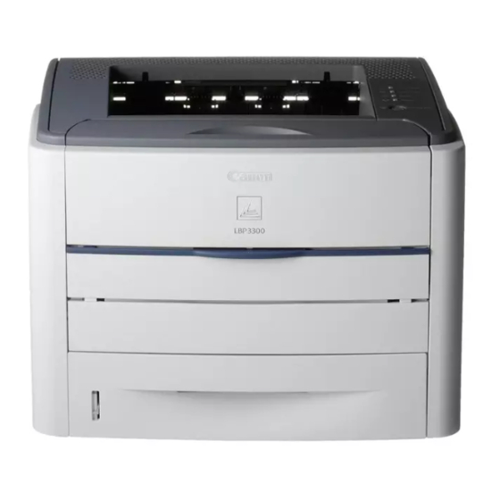
Chapter 1 1.1 Features 1.1.1 Feature 0011-2880 1. Compact, high-speed and high-resolution printer Regardless of its compact size that enables an installation on side of desks, this printer realizes the printing speed of 21 pages per minute in letter-size paper with the resolution of 600 dpi. -
Page 12: Name Of Parts
Chapter 1 Operating environment 10 to 32.5 deg C (Temperature range) Operating environment 20% to 80% RH (Humidity range) Noise 52.8 dB or less (during printing; based on ISO9296; announced noise emission) Power supply rating AC100V±10% (50/60Hz ±2Hz) Power consumption (Maximum) 790W or less (approx.; 20 deg C; for input of rated power supply; including peak value lasting 1 sec or more) Dimensions 370 (W) x 375 (D) x 258 (H)mm... -
Page 13: Cross Sectional Views
Chapter 1 1.4.2 Cross Sectional Views 0011-2878 [3] [4] [5] [15] [14] [13] [12] [11] [10] [16] [17] F-1-3 [1] Face-down delivery roller [10] Registration roller [2] Fixing film unit [11] Duplex pick-up roller [3] Laser/scanner unit [12] Registration shutter [4] Primary charging roller [13] Transfer charging roller [5] Developing cylinder... -
Page 14: Using The Machine
Chapter 1 1.5 Using the Machine 1.5.1 Control Panel 0011-2879 F-1-4 There is no paper in any paper source. [1] Load Paper Indicator Blinking: No paper or paper of an inappropriate size s loaded [2] Paper Jam Indicator Blinking A paper jam is occurring, disabling printing. Service call is occurring. - Page 15 Chapter 1 DANGER Invisible laser radiation when open. AVOID DIRECT EXPOSURE TO BEAM. CAUTION INVISIBLE LASER RADIATION WHEN OPEN. AVOID EXPOSURE TO BEAM. ATTENTION RAYONNEMENT LASER INVISIBLE EN CAS D'O UVERTURE. EXPOSITION DANGEREUSE AU FAISCEAU. VORSICHT UNSICHTBARE LASERSTRAHLUNG. WENN ABDECKUNG GEOFFNET. NICHT DEM STRAHL AUSSETZEN.
-
Page 16: Chapter 2 Technical Reference
Chapter 2 TECHNICAL REFERENCE... - Page 17 Contents Contents 2.1 Functional Configuration ...............................2-1 2.1.1 Outline......................................2-1 2.2 Basic Sequense................................2-1 2.2.1 Basic Operation Sequence ................................2-1 2.2.2 Power-on sequence ..................................2-1 2.3 LASER EXPOSURE SYSTEM.............................2-2 2.3.1 Overview/Configuration ................................2-2 2.3.1.1 Outline..........................................2-2 2.3.1.2 Laser Control Circuit.......................................2-3 2.3.2 Controlling the Laser Activation Timing............................. 2-5 2.3.2.1 Laser emission control ....................................2-5 2.3.2.2 Horizontal synchronous control ..................................2-5 2.3.3 Laser Control ....................................
- Page 18 Contents 2.5.3 Cassette Pickup ..................................2-15 2.5.3.1 Cassette pick-up ......................................2-15 2.5.4 Multi-purpose Pickup................................. 2-15 2.5.4.1 Manual feed ........................................2-15 2.5.5 Duplex Feeding..................................2-16 2.5.5.1 Outline .......................................... 2-16 2.5.5.2 Operation ........................................2-17 2.6 EXTERNAL AND CONTROLS SYSTEM ....................... 2-17 2.6.1 Fan......................................2-17 2.6.1.1 Fan motor control......................................
-
Page 19: Functional Configuration
Chapter 2 2.1 Functional Configuration 2.1.1 Outline 0011-2515 The machine may be broadly divided into the following 6 functional blocks: engine control system, laser exposure system, image formation system, pickup/trans- port/delivery system, fixing system, and externals/auxiliary control system. Laser exposure system Image formation system Pickup/transport/delivery system Engine control... -
Page 20: Laser Exposure System
Chapter 2 2.3 LASER EXPOSURE SYSTEM 2.3.1 Overview/Configuration 2.3.1.1 Outline 0011-2430 The laser/scanner system consists of the laser driver and the scanner motor etc. It is controlled by the signals sent from the engine controller and the video controller. The laser driver allows the laser diode to emit light according to the LASER CONTROL signals (CNT0, CNT1, CNT2) from the engine controller or the VIDEO signals (/VDO1, /VDO2, VDO1, VDO2) from the video controller. -
Page 21: Laser Control Circuit
Chapter 2 1st scanning line 2nd scanning line LD1 scanning line 3rd scanning line LD2 scanning line 4th scanning line Feed direction Image area F-2-3 2.3.1.2 Laser Control Circuit 0011-2436 The laser control controls the laser driver to turn the two laser diodes (LD1, LD2) ON/OFF according to the LASER CONTROL signals sent from the engine con- troller. - Page 22 Chapter 2 Engine Video Laser driver PCB controller PCB controller PCB J201 J801 VDO1 switching switching /VDO1 circuit circuit VDO2 /VDO2 Comparator Comparator Reference voltage IC201 C802 C803 Sample Sample hold circuit hold circuit CNT0 /CNT0 CNT1 Logic circuit /CNT1 CNT2 /CNT2 Laser driver IC...
-
Page 23: Controlling The Laser Activation Timing
Chapter 2 2.3.2 Controlling the Laser Activation Timing 2.3.2.1 Laser emission control 0011-2441 The laser emission control controls the laser diodes (LD1, LD2) to turn ON/OFF at constant light intensity according to the VIDEO signals (VDO1, /VDO1, VDO2, /VDO2) from the video controller. When the LASER CONTROL signals (CNT0, CNT1, CNT2) are put into print mode, the laser driver turns the laser diodes ON/OFF according to the VIDEO sig- nals. -
Page 24: Laser Scanner Motor Control
Chapter 2 /BDO Unmasking area 0 mm 0 mm F-2-5 1) The shaded area indicates the area an image can be written by the laser beam. 2) T1 indicates the area of left /right outsides 0 mm of letter sized paper despite a paper size is specified or not. 3) T2 indicates the area of 2 mm behind the leading edge of the paper (where the /BDO signal starts to output) to the trailing edge. -
Page 25: Scanner Motor Speed Control
Chapter 2 Engine controller PCB Video controller PCB Laser/scanner unit J801 J201 /BDI BD sensor IC201 +24VA +24VA J802 Scanner driver IC /ACC Frequency Integrated Drive comparator circuit circuit /DEC Reference clock Divider X201 Scanner motor F-2-6 2.3.4.2 Scanner motor speed control 0011-2449 The scanner motor is 3-phase DC brushless motor unified with the hole effect device and it is unified with the drive circuit. -
Page 26: Print Process
Chapter 2 The latent image formed on the photosensitive drum is transferred into a visible image by the toner on the developing cylinder and the transfer charging roller trans- fers it onto a print paper. Then the transferred toner onto a paper becomes a permanent image by heat and pressure in the fixing unit. After the surface of the pho- tosensitive drum is cleaned by the cleaning blade, the drum potential is uniformed by the primary charging roller to get ready for the next print. -
Page 27: Development Block
Chapter 2 When the last step in this block is complete, a negative electrical charge is remained in the unexposed drum surface area by the laser beam and it is removed from the exposed area. The image with a negative charge on the drum is called an "electrostatic latent image" as it is invisible to the human eyes. Time (t) Exposed area -100... -
Page 28: Transfer Block
Chapter 2 Blade Photosensitive Stirrer drum Cylinder Developing cylinder Magnet AC bias DC bias F-2-12 The exposed area on the photosensitive drum is indicated positive in figure despite of the fact that the actual potential on the drum is negative. This means that the potential of the photosensitive drum is higher than that of the cylinder relative to the potential of the cylinder. -
Page 29: Fixing Block
Chapter 2 Photo- sensitive Paper drum Static charge eliminator Transfer charging roller F-2-15 A print paper is separated from the drum by its elasticity. (Curvature Separation) The static charge on the back side of a print paper is decreased with the electrostatic eliminator after the transfer process in order to stable the feeding operation and prevent the crescent spots of printing image under the L/L environment. -
Page 30: Primary Charging Bias Generation
Chapter 2 The primary charging bias circuit generates the negative DC voltage and AC voltage. They are superimposed and applied to the primary charging roller. The circuit also applies the negative DC voltage to the fixing film unit through the pressure roller. In addition, this circuit detects the presence of cartridge. The developing bias circuit generates negative DC voltage and AC voltage. -
Page 31: Fixing Bias Generation
Chapter 2 negative bias is applied to the transfer charging roller. The CPU controls a constant current control by switching the values of the TRPWM signal in response to the TRANSFER CURRET FEEDBACK signal (TFRAD) sent from the transfer charging bias circuit. The transfer charging roller is applied with the cleaning bias, the between-sheets bias, and the print bias according to each print equence. -
Page 32: Detecting Jams
Chapter 2 ENGINE CONTROLLER PCB PS915 PS913 PS915 PS911 PS912 Registration shutter PS914 Separation F-2-19 M1: Main Motor SL1: Cassette pick-up solenoid SL2: Manual feed solenoid SL3: Reversing solenoid 2.5.2 Detecting Jams 2.5.2.1 Jam Detection Outline 2.5.2.1.1 Outline 0011-2465 This printer is provided the following paper detection sensors to detect the presence of the paper and weather the paper feed is operated normally or not. 1: Top of page sensor (PS912) 2: Delivery sensor/Reversing sensor (PS915) The CPU determines a paper jam by checking whether the paper is present at the sensor or not at the checking timing. -
Page 33: Delay Jams
Chapter 2 2.5.2.2 Delay Jams 2.5.2.2.1 Pick-up delay jam 0011-2466 The printer performs the retry control, which executes pick-up operation twice, in order to relief the pick-up delay jam caused by pick-up error. When the top of page sensor (PS912) cannot detect the leading edge of the paper within approx. 2.7 sec. (3.4 sec. for the optional cassette) after when the pick-up solenoid (SL1) is turned ON, the CPU retries the pick-up operation twice. -
Page 34: Duplex Feeding
Chapter 2 The manual feed pick-up operation is explained in the following. 1) When a paper is set in the manual feed slot at stand by status, the engine controller turns the manual feed solenoid (SL2) ON to fix the registration roller. 2) The engine controller drives the main motor (M1) for 1 sec. -
Page 35: Operation
Chapter 2 Face-down delivery roller Reversing sensor Delivery sensor Oblique roller F-2-21 2.5.5.2 Operation 0011-2464 The duplex feed unit is driven by the main motor (M1). When the first side of print paper is printed, the paper is once fed to the face-down tray. The engine controller turns the reversing solenoid (SL3) ON after approx. -
Page 36: Power Supply
Chapter 2 into "L". When the FLOCK indicates "L", the CPU determines the fan rotates normally. After the print operation is completed and the main motor stops, the CPU rotates the fan motor for approx. 30 sec. and puts the FANON into "L" to stop the fan motor. The CPU determines the fan motor failure and notifies it to the video controller under the following condition. -
Page 37: Protective Functions
Chapter 2 Power switch (SW101) Engine control PCB Low-voltage power Fixing heater supply circuit Relay Triac (RL101) Fuse Fixing heater (FU101) safety circuit High-voltage Noise power supply filter circuit Fuse (FU102) 110-127V only Door switch (IC201) (SW301) Noise filter +24U Rectification Fan motor Fan motor... -
Page 38: Engine Control System
Chapter 2 2.7 ENGINE CONTROL SYSTEM 2.7.1 Video Controller 2.7.1.1 Outline 0011-5367 The video controller receives print information from an external device (e.g., host computer) through an interface cable. The print information includes the CAPT command used to communicate printer status and unique information and dot data, which is the result of conversion of resource type print data by the host computer. The dot data is sent to the engine controller for control of the activation of the laser diode. - Page 39 Chapter 2 Engine controller PCB Main motor Fixing control Fixing unit circuit Solenoids Low-voltage power AC input Sensors supply circuit Fan motor drive Duplex driver circuit IC201 IC502 Reset IC Transfer Option charging roller High-voltage power supply Pressure roller circuit Cartridge Memory tag circuit Scanner motor...
-
Page 40: Fixing Unit/Delivery System
Chapter 2 2.8 FIXING UNIT/DELIVERY SYSTEM 2.8.1 Overview/Configuration 2.8.1.1 Outline 0011-2486 The fixing/delivery unit fixes the toner onto a print paper and delivers it to the delivery tray. The operation of the fixing/delivery unit is explained in the following. 1) The print paper fed from the pick-up/feed unit is fused the toner by the fixing film and the pressure roller. 2) The print paper delivered from the fixing unit is delivered to the face-down delivery tray or the face-up delivery slot. -
Page 41: Various Control Mechanisms
Chapter 2 2.8.2 Various Control Mechanisms 2.8.2.1 Fixing Temperature Control 2.8.2.1.1 Fixing temperature control 0011-2488 The fixing temperature control detects the surface temperature of the fixing heater. It controls the drive signals of the fixing heater and maintains its temperature at the targeted temperature. -
Page 42: Protective Functions
Chapter 2 temperature rise of betweensheets. The temperature of the fixing heater is detected by the thermistor (TH1) on the fixing heater. If the surface temperature rises, the resistance value of the thermistor decreases, which allows the voltage of the FIXING HEATER TEMPERATURE signal (FSRTH) to decrease. -
Page 43: Chapter 3 Disassembly And Assembly
Chapter 3 DISASSEMBLY AND ASSEMBLY... - Page 44 Contents Contents 3.1 EXTERNAL AND CONTROLS SYSTEM ........................3-1 3.1.1 Rear Cover ....................................3-1 3.1.1.1 Preparation for removing the rear cover unit..............................3-1 3.1.1.2 Removing the rear cover unit..................................3-1 3.1.2 Right Cover ....................................3-1 3.1.2.1 Detaching the right cover ....................................3-1 3.1.3 Left Cover ....................................
- Page 45 Contents 3.4.4.2 Removing the manual pick-up solenoid ................................. 3-7 3.4.5 Registration Roller ..................................3-7 3.4.5.1 Preparation for removing the registration roller ............................. 3-7 3.4.5.2 Removing the registration roller ..................................3-7 3.4.6 Main Motor ....................................3-7 3.4.6.1 Preparation for removing the main motor............................... 3-7 3.4.6.2 Removing the main motor ....................................
-
Page 46: External And Controls System
Chapter 3 3.1 EXTERNAL AND CONTROLS SYSTEM 3.1.2 Right Cover 3.1.2.1 Detaching the right cover 3.1.1 Rear Cover 0011-2773 1) Open the front cover [1]. 3.1.1.1 Preparation for removing the rear cover unit. 0011-2776 1) Detach the left cover. (page 3-1)Reference[Detaching the left cover] 2) Detach the right cover. -
Page 47: Detaching The Upper Cover Unit
Chapter 3 3.1.4.2 Detaching the upper cover unit - A screw [2] 0011-2787 1) Detach the control panel [1] - 2 claws [2] - A connector [3] F-3-13 2) Move the arm [1] to release from the boss [2]. F-3-9 F-3-14 3) Remove the front cover unit [1]. -
Page 48: Duplexing Drive Unit
Chapter 3 F-3-17 F-3-21 3) Disengage the gear [1]. 3) Remove the duplexing drive assembly [1]. - 3 screws [2] F-3-18 F-3-22 4) Release the cartridge arm [1]. - A claw [2] The gear of the duplexing drive assembly is not fixed to the sheet metal. Therefore, be careful that they do not come apart when removing the assem- bly. -
Page 49: Engine Controller Board
Chapter 3 3.1.9 Engine controller board 3.1.9.1 Preparation for removing the engine controller 0011-5000 1) Detach the left cover. (page 3-1)Reference[Detaching the left cover] 2) Detach the right cover. (page 3-1)Reference[Detaching the right cover] 3) Detach the rear cover. (page 3-1)Reference[Removing the rear cover unit.] 4) Detach the upper cover. -
Page 50: Video Controller Board
Chapter 3 3.1.11 Video Controller Board 3.1.11.1 Removing the video controller PCB 0011-5173 1) Detach the left cover. (page 3-1)Reference[Detaching the left cover] 2) Unscrew two screws [1] of the rear cover. F-3-36 4) Remove the USB PCB [1]. - A connector [2] - 3 screws [3] F-3-32 3) Remove the sheet metal [1]. -
Page 51: Removing The Fan
Chapter 3 3.1.14.2 Removing the fan 0011-4999 1) Disconnect the connector [1] and release it from the harness guide. - A connector [1] F-3-44 F-3-40 When assembling / disassembling the transfer corona roller, be sure to hold the shaft or shaft support of the roller. Do not hold the sponge. 2) Remove the fan [1]. -
Page 52: Cassette Separation Pad
Chapter 3 - 5 screws [2] F-3-47 F-3-50 3.4.3 Cassette Separation Pad 3.4.6 Main Motor 3.4.3.1 Removing the separation pad 3.4.6.1 Preparation for removing the main motor 0011-4965 1) Pull out the cassette. 0011-5001 2) Remove the separation pad [1]. 1) Detach the left cover. -
Page 53: Duplexing Unit
Chapter 3 3.4.8 Duplexing Unit 3.5 FIXING SYSTEM 3.4.8.1 Preparation for removing the duplexing unit 3.5.1 Fixing Unit 0011-5162 1) Detach the left cover. (page 3-1)Reference[Detaching the left cover] 3.5.1.1 Preparation for removing the fixing assembly 2) Detach the right cover. (page 3-1)Reference[Detaching the right cover] 0011-4911 1) Detach the left cover. -
Page 54: Fixing Film Unit
Chapter 3 3.5.2 Fixing Film Unit 3.5.2.1 Preparation for removing the fixing film unit 0011-4916 1) Detach the left cover. (page 3-1)Reference[Detaching the left cover] 2) Detach the right cover. (page 3-1)Reference[Detaching the right cover] 3) Detach the rear cover. (page 3-1)Reference[Removing the rear cover unit.] 4) Detach the upper cover. -
Page 55: Fixing Pressure Roller
Chapter 3 F-3-68 F-3-71 5) Remove the spring [1]. 6) Remove the fixing film. - 4 Bosses [3] (2 each at right and left) - 2 pressure plates [4] (Right and left) F-3-69 3.5.3 Fixing Pressure Roller 3.5.3.1 Preparation for removing the fixing pressure roller 0011-4966 1) Detach the left cover. -
Page 56: Chapter 4 Maintenance And Inspection
Chapter 4 MAINTENANCE AND INSPECTION... - Page 57 Contents Contents 4.1 Periodically Replaced Parts ............................4-1 4.1.1 Periodically Replaced Parts ................................. 4-1 4.2 Consumables ..................................4-1 4.2.1 Life Expectancy of Consumable Parts ............................4-1 4.3 Periodical Service ................................4-1 4.3.1 Periodic Service ................................... 4-1 4.4 Cleaning ..................................4-1 4.4.1 Cleaning During Service Visit ..............................4-1...
-
Page 58: Periodically Replaced Parts
Chapter 4 4.1 Periodically Replaced Parts 4.1.1 Periodically Replaced Parts 0011-2517 The machine does not have parts that require periodical replacement. 4.2 Consumables 4.2.1 Life Expectancy of Consumable Parts 0011-2518 No consumable parts are required in this printer. 4.3 Periodical Service 4.3.1 Periodic Service 0011-2519 No periodic services are required to this printer. -
Page 59: Chapter 5 Troubleshooting
Chapter 5 TROUBLESHOOTING... - Page 60 Contents Contents 5.1 MEASUREMENT AND ADJUSTMENT ........................5-1 5.1.1 Test Print ...................................... 5-1 5.1.1.1 Test Print .........................................5-1 5.1.2 Mechanical Adjustment ................................5-1 5.1.2.1 Checking the Nip Width (fixing pressure roller) ............................5-1 5.2 SERVICE TOOLS .................................5-2 5.2.1 Standard Tools ..................................... 5-2 5.2.2 Special Tools....................................5-2 5.2.3 Solvent/Oil List ....................................
-
Page 61: Measurement And Adjustment
Chapter 5 5.1 MEASUREMENT AND ADJUSTMENT 5.1.1 Test Print 5.1.1.1 Test Print 0011-5471 This test print is conducted in order to check if the printer engine works nor- mally. When this test printing is made, the test print pattern (horizontal lines) is printed as shown below. -
Page 62: Service Tools
Chapter 5 5.2 SERVICE TOOLS 5.2.1 Standard Tools 0011-5458 The table below lists the standard tools required for servicing the printer. T-5-1 Tool name Tool No. Remark Tool case TKN-0001 With a clip Jumper wire TKN-0069 0.02 to 0.3 mm Clearance gauge CK-0057 0 to 600 g for checking the cassette spring pressure... - Page 63 Chapter 6 APPENDIX...
- Page 64 Contents Contents 6.1 OUTLINE OF ELECTRICAL COMPONENTS......................6-1 6.1.1 Clutch/Solenoid.................................... 6-1 6.1.1.1 Solenoid...........................................6-1 6.1.2 Motor......................................6-1 6.1.2.1 Motor..........................................6-1 6.1.3 Fan........................................ 6-2 6.1.3.1 Fan...........................................6-2 6.1.4 Sensor......................................6-2 6.1.4.1 Sensor ..........................................6-2 6.1.5 PCBs ......................................6-3 6.1.5.1 PCB ..........................................6-3...
- Page 65 Chapter 6 6.1 OUTLINE OF ELECTRICAL COMPONENTS 6.1.1 Clutch/Solenoid 6.1.1.1 Solenoid 0011-2589 F-6-1 Reversal solenoid Cassette pick-up solenoid Manual feed pick-up solenoid 6.1.2 Motor 6.1.2.1 Motor 0011-2594 F-6-2 Main motor...
- Page 66 Chapter 6 6.1.3 Fan 6.1.3.1 Fan 0011-2597 F-6-3 T-6-1 6.1.4 Sensor 6.1.4.1 Sensor 0011-2584 F-6-4 Interlock switch Top of page sensor/Paper width detection sensor Delivery sensor...
- Page 67 Chapter 6 6.1.5 PCBs 6.1.5.1 PCB 0011-2607 F-6-5 Display PCB Duplexing driver PCB Engine controller PCB Video controller PCB USB conector PCB...
- Page 68 PARTS CATALOG LBP3300/LBP3360 Sep 19 2006...
- Page 69 Contents NUMERICAL INDEX LBP3300/LBP3360 ................1-1 LBP3300/LBP3360 ASSEMBLY LOCATION DIAGRAM ........2-1 DISK UNIT ................2-2 EXTERNAL COVERS, PANELS, ETC........2-3 INTERNAL COMPONENTS 1 ..........2-6 INTERNAL COMPONENTS 2 ..........2-8 INTERNAL COMPONENTS 3 ..........2-10 INTERNAL COMPONENTS 4 ..........2-12 ENGINE CONTROLLER ASS'Y ..........2-14 MAIN DRIVE ASS'Y .............2-16 DUPLEXING DRIVE ASS'Y ..........2-17 CASSETTE ................2-18 DUPLEXING ASS'Y .............2-20...
-
Page 70: Numerical Index
NUMERICAL INDEX LBP3300/LBP3360 FIGURE FIGURE FIGURE PARTS NUMBER & PARTS NUMBER & PARTS NUMBER & KEY NO. KEY NO. KEY NO FC5-4820-000 FM2-6701-000 RC1-3550-000 FC7-0779-000 FM2-6702-000 RC1-3551-000 FC7-0780-000 FM2-6703-000 RC1-3552-000 FC7-0781-000 FM2-6704-000 RC1-3561-000 FC7-0782-000 FM2-6707-000 RC1-3562-000 FC7-0783-000 FM2-6708-000 RC1-3580-000 FC7-0792-000 FM2-6709-000 RC1-3603-000 FC7-0793-000... - Page 71 NUMERICAL INDEX LBP3300/LBP3360 FIGURE FIGURE FIGURE PARTS NUMBER & PARTS NUMBER & PARTS NUMBER & KEY NO. KEY NO. KEY NO RH9-1169-000 XA9-1503-000 RK2-0419-000 XA9-1503-000 RK2-0420-000 XA9-1503-000 RK2-0424-000 XA9-1504-000 RK2-0428-000 XA9-1504-000 RK2-1302-000 XA9-1504-000 RK2-1315-000 XA9-1648-000 RL1-0527-000 XB2-6400-607 RL1-0540-000 XB4-7300-809 RM1-1242-030 XB4-7401-005 RM1-1243-030 XB4-7401-005...
-
Page 72: Lbp3300/Lbp3360
LBP3300/LBP3360 LBP3300 100V JP F14-8301-000 120V F14-8331-000 230V CN F14-8351-000 230V EUR/UK/ F14-8391-000 ASIA/AU LBP3360 230V ASIA/AU F14-9641-000 230V CN F14-9651-000 230V EUR F14-9691-000... - Page 73 Contents ASSEMBLY LOCATION DIAGRAM ..............2-1 DISK UNIT ......................2-2 EXTERNAL COVERS, PANELS, ETC...............2-3 INTERNAL COMPONENTS 1 ................2-6 INTERNAL COMPONENTS 2 ................2-8 INTERNAL COMPONENTS 3 ................2-10 INTERNAL COMPONENTS 4 ................2-12 ENGINE CONTROLLER ASS'Y ...............2-14 MAIN DRIVE ASS'Y..................2-16 DUPLEXING DRIVE ASS'Y ................2-17 CASSETTE .......................2-18 DUPLEXING ASS'Y ..................2-20 FIXING ASS'Y....................2-21...
-
Page 74: Assembly Location Diagram
FIGURE A ASSEMBLY LOCATION DIAGRAM DUPLEXING DRIVE ASS'Y MAIN DRIVE ASS'Y CASSETTE FIXING ASS'Y DUPLEXING ASS'Y ENGINE CONTROLLER ASS'Y... -
Page 75: Disk Unit
FIGURE 001 DISK UNIT LBP3360 FIGURE PARTS SERIAL NUMBER/ & KEY Q'TY DESCRIPTION NUMBER REMARKS Fig.001 DISK UNIT FK2-4776-000 CD-ROM, USER SOFTWARE LBP3300 EUR FK2-3466-000 CD-ROM, USER SOFTWARE LBP3300 Japanese LBP3300 Simplified FK2-2861-000 CD-ROM, USER SOFTWARE Chinese/Korean/ Portuguese FK2-4408-000 CD-ROM, USER SOFTWARE LBP3360 English WE8-5689-000 FILTER, NOISE(RING CORE) -
Page 76: External Covers, Panels, Etc
FIGURE 100 EXTERNAL COVERS, PANELS, ETC. LBP3360 LBP3300 ASIA / KOR LBP3300 100V ONLY (J101) (J2) (J101) (J10) LBP3300 LBP3360 SEE FIGURE 300... - Page 77 FIGURE PARTS SERIAL NUMBER/ & KEY Q'TY DESCRIPTION NUMBER REMARKS Fig.100 EXTERNAL COVERS, PANELS, ETC. FC5-4820-000 EMBLEM, SATERA 100V RC1-6217-000 EMBLEM, LASER SHOT 120/230V FC7-0779-000 PLATE, LOGO FC7-0781-000 SHEET, CONTROL PANEL LBP3300 ASIA FC7-1521-000 SHEET, CONTROL PANEL LBP3300 KOR FC7-0780-000 COVER, TOP LBP3300 FC7-3184-000...
- Page 78 FIGURE PARTS SERIAL NUMBER/ & KEY Q'TY DESCRIPTION NUMBER REMARKS LBP3300 120V/EUR/UK/ FC7-0804-000 PANEL, CONTROL ASIA/AU FC7-0803-000 PANEL, CONTROL LBP3300 JP FM2-6194-000 DISPLAY PCB ASS'Y LBP3300 FM2-6196-000 CABLE, PANEL LBP3300 J2,101 FC7-3050-000 LABEL, PAPER SIZE LBP3300 100V FC7-1518-000 LABEL, PAPER SIZE LBP3300 120/230V FC7-3201-000 LABEL, PAPER SIZE...
-
Page 79: Internal Components 1
FIGURE 101 INTERNAL COMPONENTS 1 SEE FIGURE 251 SEE FIGURE 810 SEE FIGURE FIGURE PARTS SERIAL NUMBER/ & KEY Q'TY DESCRIPTION NUMBER REMARKS Fig.101 INTERNAL COMPONENTS 1 RC1-3546-000 CAM, RIGHT... - Page 80 FIGURE PARTS SERIAL NUMBER/ & KEY Q'TY DESCRIPTION NUMBER REMARKS RC1-3665-000 BUSHING FC7-3047-000 LINK, GEAR RELEASE RL1-0527-000 ROLLER, FACE-DOWN RK2-0420-000 SOLENOID SL3 J1101 RU5-0332-000 GEAR, 19T FM2-6188-000 MANUAL PAPER FEED ASS'Y RC1-3731-020 GUIDE, DC CABLE, 2 XA9-1503-000 SCREW, TAP, M3X6 XA9-1495-000 SCREW, RS, M3X6 RM1-1286-000...
-
Page 81: Internal Components 2
FIGURE 102 INTERNAL COMPONENTS 2 SEE FIGURE 360 100V ONLY SEE FIGURE 110 FIGURE PARTS SERIAL NUMBER/ & KEY Q'TY DESCRIPTION NUMBER REMARKS Fig.102 INTERNAL COMPONENTS 2 RC1-3537-000 HOLDER, FAN RC1-3539-020 GUIDE, CARTRIDGE, LEFT UPPER RC1-3540-020 SPRING, TORSION RC1-3544-020 ARM, CAM... - Page 82 FIGURE PARTS SERIAL NUMBER/ & KEY Q'TY DESCRIPTION NUMBER REMARKS RC1-3550-000 HOLDER, TAG ARM RC1-3551-000 ARM, TAG RC1-3552-000 ROD, GROUNDING RC1-3561-000 ARM, LOCK RC1-3562-000 BUSHING RC1-3580-000 STOPPER RC1-3666-000 GUIDE, THERMISTOR CABLE RC1-3667-000 GUIDE, DC CABLE, 1 RC1-3728-000 HOLDER, DRAWER RC1-3773-000 BUSHING RC1-3827-000 SHIELD, DUPLEXING SOLENOID...
-
Page 83: Internal Components 3
FIGURE 103 INTERNAL COMPONENTS 3 FIGURE PARTS SERIAL NUMBER/ & KEY Q'TY DESCRIPTION NUMBER REMARKS FM2-6189-000 REGISTRATION ASS'Y RM1-1283-000 TOP SENSOR ASS'Y 2-10... - Page 84 FIGURE PARTS SERIAL NUMBER/ & KEY Q'TY DESCRIPTION NUMBER REMARKS RM1-1471-000 ROLLER, TRANSFER FC7-0799-000 LABEL, CLEAR JAM FC7-0806-000 LABEL, TRANSFER GUIDE OPEN FC7-0800-000 LABEL, FIXING PRESSURE RELEASE RC1-3702-000 SPRING, TRANSFER, RIGHT RC1-3708-000 COVER, REGISTRATION GEAR XB4-7401-005 SCREW,TAPPING,TRUSS HEAD,M4X10 2-11...
-
Page 85: Internal Components 4
FIGURE 104 INTERNAL COMPONENTS 4 (ASIA/EUR) (AU) (100V) (120V) (CN) (UK) 100V ONLY LBP3300 LBP3360 2-12... - Page 86 FIGURE PARTS SERIAL NUMBER/ & KEY Q'TY DESCRIPTION NUMBER REMARKS Fig.104 INTERNAL COMPONENTS 4 RK2-0419-000 MOTOR, DC M1 J202 RK2-0424-000 SOLENOID SL1 J207 RM1-1249-000 INLET/SWITCH CABLE ASS'Y FC7-0792-000 RAIL, NIC, UPPER LBP3300 FC7-0793-000 RAIL, NIC, LOWER LBP3300 FM2-9333-000 VIDEO CONTROLLER PCB ASS'Y LBP3300 100V FM2-9334-000 VIDEO CONTROLLER PCB ASS'Y...
-
Page 87: Engine Controller Ass'y
FIGURE 110 ENGINE CONTROLLER ASS'Y FIGURE PARTS SERIAL NUMBER/ & KEY Q'TY DESCRIPTION NUMBER REMARKS Fig.110 FM2-6719-000 ENGINE CONTROLLER ASS'Y LBP3300 100V Fig.110 RM1-1300-030 ENGINE CONTROLLER ASS'Y LBP3300 120V Fig.110 RM1-1462-030 ENGINE CONTROLLER ASS'Y LBP3300 230V Fig.110 FM2-8343-000 ENGINE CONTROLLER ASS'Y LBP3360 FM2-8283-000 ENGINE CONTROLLER PCB ASS'Y... - Page 88 FIGURE PARTS SERIAL NUMBER/ & KEY Q'TY DESCRIPTION NUMBER REMARKS FM2-8327-000 ENGINE CONTROLLER PCB ASS'Y LBP3360 2-15...
-
Page 89: Main Drive Ass'y
FIGURE 250 MAIN DRIVE ASS'Y FIGURE PARTS SERIAL NUMBER/ & KEY Q'TY DESCRIPTION NUMBER REMARKS Fig.250 RM1-1299-020 MAIN DRIVE ASS'Y 2-16... -
Page 90: Duplexing Drive Ass'y
FIGURE 251 DUPLEXING DRIVE ASS'Y FIGURE PARTS SERIAL NUMBER/ & KEY Q'TY DESCRIPTION NUMBER REMARKS Fig.251 RM1-1302-000 DUPLEXING DRIVE ASS'Y RM1-1303-000 NORMAL ROTATION DRIVE ASS'Y RM1-1304-000 REVERSE ROTATION DRIVE ASS'Y 2-17... -
Page 91: Cassette
FIGURE 300 CASSETTE FIGURE PARTS SERIAL NUMBER/ & KEY Q'TY DESCRIPTION NUMBER REMARKS Fig.300 FM2-6190-000 CASSETTE FM2-6191-000 CASSETTE COVER ASS'Y FM2-6192-000 CASSETTE BODY ASS'Y RM1-1295-000 BACK END LIMIT ASS'Y RM1-1296-000 LEFT PAPER SIDE END ASS'Y 2-18... - Page 92 FIGURE PARTS SERIAL NUMBER/ & KEY Q'TY DESCRIPTION NUMBER REMARKS RM1-1297-020 RIGHT PAPER SIDE END ASS'Y FM2-6707-000 SEPARATION PAD ASS'Y 2-19...
-
Page 93: Duplexing Ass'y
FIGURE 360 DUPLEXING ASS'Y FIGURE PARTS SERIAL NUMBER/ & KEY Q'TY DESCRIPTION NUMBER REMARKS Fig.360 RM1-1313-000 DUPLEXING ASS'Y RM1-1314-000 STANDARD GUIDE ASS'Y RM1-1319-000 DUPLEX PENDULUM ASS'Y RM1-1317-020 DUPLEXING OUTLET GUIDE ASS'Y RM1-1318-000 SIZE CHANGE ASS'Y 2-20... -
Page 94: Fixing Ass'y
FIGURE 810 FIXING ASS'Y 2-21... - Page 95 FIGURE PARTS SERIAL NUMBER/ & KEY Q'TY DESCRIPTION NUMBER REMARKS Fig.810 FM2-6717-000 FIXING ASS'Y 100/120V Fig.810 FM2-6718-000 FIXING ASS'Y 230V RM1-1251-000 DELIVERY SENSOR PCB ASS'Y PS915 J915 RU5-2140-000 SPRING, COMPRESSION FM2-6703-000 FILM GUIDE ASS'Y 100/120V FM2-6704-000 FILM GUIDE ASS'Y 230V RM1-1291-000 DELIVERY FRAME ASS'Y RA0-1090-000...
- Page 96 FIGURE PARTS SERIAL NUMBER/ & KEY Q'TY DESCRIPTION NUMBER REMARKS RC1-3628-000 RING, CONDUCTIVE RUBBER RC1-3630-000 ROLLER, PRESSURE RC1-3633-000 ROLLER, FACE-UP RC1-3635-000 SHEET, FIXING BOTTOM SHEET RU5-0330-000 GEAR, 17T FC7-3048-000 GUIDE, FILM XB4-7300-809 SCREW, TAP, BINDING HEAD, M3X8 2-23...