Toro Reelmaster 5610-D Owner's Manual
Hide thumbs
Also See for Reelmaster 5610-D:
- Operator's manual (124 pages) ,
- Service manual (662 pages) ,
- Installation instructions manual (8 pages)

Related Manuals for Toro Reelmaster 5610-D


Summary of Contents for Toro Reelmaster 5610-D
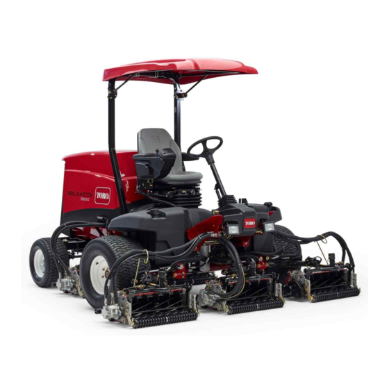
- Page 1 Form No. 3450-425 Rev A Reelmaster ® 5610-D Traction Unit Model No. 03679—Serial No. 410400000 and Up *3450-425* Register at www.Toro.com. Original Instructions (EN)
- Page 2 Whenever you need service, genuine Toro parts, or additional information, contact an Authorized Service Dealer or Toro Customer Service and have the model and serial numbers of your product ready. Figure 1 identifies the location of the model and serial numbers on the product.
-
Page 3: Table Of Contents
Contents Fuel System Maintenance ........59 Draining Water from the Fuel-Water Separator ............59 Safety ................4 Replacing the Water-Separator Filter ...... 60 General Safety............4 Replacing the Engine Fuel Filter ......60 Engine Emission Certification ........4 Checking the Fuel Lines and Connections....60 Safety and Instructional Decals ........ -
Page 4: Safety
Safety This machine has been designed in accordance with EN ISO 5395 (when you complete the setup procedures) and ANSI B71.4-2017. General Safety This product is capable of amputating hands and feet and of throwing objects. • Read and understand the contents of this Operator’s Manual before starting the engine. -
Page 5: Safety And Instructional Decals
Safety and Instructional Decals Safety decals and instructions are easily visible to the operator and are located near any area of potential danger. Replace any decal that is damaged or missing. decal106-6754 decalbatterysymbols 106-6754 Battery Symbols 1. Warning—do not touch the hot surface. Some or all of these symbols are on your battery. - Page 6 decal110-8921 110-8921 1. Traction unit speed 2. Slow 3. Fast decal110-9642 110-9642 1. Stored energy hazard—read the Operator's Manual. 2. Move the cotter pin to the hole closest to the rod bracket and then remove the lift arm and pivot yoke. decal125-8754 125–8754 1.
- Page 7 decal145-5261 145-5261 1. Read the 4. Electric 7. TEC controller Operator's Manual for fuse information. 2. Power point (12 5. Engine start 8. TEC controller 3. Headlights 6. Air ride seat 9. TEC controller suspension (optional) decal133-2930 133-2930 1. Warning—do not operate this machine unless you are trained. 4. Tipping hazard—drive slowly when turning; do not turn sharply while traveling fast;...
- Page 8 CE Machines decal133-2931 133-2931 Note: This machine complies with the industry standard stability test in the static lateral and longitudinal tests with the maximum recommended slope indicated on the decal. Review the instructions for operating the machine on slopes in the Operator’s Manual as well as the conditions in which you would operate the machine to determine whether you can operate the machine in the conditions on that day and at that site.
- Page 9 decal136-3723 136-3723 1. Brake functions 8. Battery 15. Fuel/Water separator 2. Check every 8 hours. 9. Radiator screen 16. Fluids 3. Hydraulic fluid 10. Engine oil 17. Capacity 4. Tire pressure 11. Engine oil level 18. Fluid interval (hours) 5. Engine air filter 12.
-
Page 10: Setup
Setup Loose Parts Use the chart below to verify that all parts have been shipped. Procedure Description Qty. – No parts required Prepare the machine. – No parts required Adjust the control-arm position. Right front hose guide Install the cutting units. Left front hose guide Cutting-unit kickstand Install the cutting-unit kickstand. -
Page 11: Adjusting The Control-Arm Position
Adjusting the Control-Arm Position No Parts Required Procedure You can adjust the control-arm position for your comfort. Loosen the 2 bolts securing the control arm to the g003975 retaining bracket (Figure Figure 4 1. Lynch pin 2. Cap Preparing the Cutting Units Remove the cutting units from the cartons. - Page 12 Positioning the Turf Compensating Spring and Installing the Hose Guide Cutting Units 4 g375690 g375671 Figure 8 Figure 6 1. Carriage bolt (3/8 x 1-1/4 3. Flange locknut (3/8 inch) 1. Cutting unit 1 5. Cutting unit 5 inches) 2. Cutting unit 2 6.
- Page 13 Installing the Hose Guide Cutting Units 5 g375672 Figure 12 g375694 Figure 10 1. Cutting unit 1 5. Cutting unit 5 2. Cutting unit 2 6. Reel motor 1. Flange locknut (3/8 inch) 3. Capscrew 3. Cutting unit 3 7. Weight 2.
- Page 14 Positioning the Turf Compensating Spring Cutting Unit 2 g379514 Figure 16 g375690 1. Cutting unit 1 5. Cutting unit 5 Figure 14 2. Cutting unit 2 6. Reel motor 1. Carriage bolt (3/8 x 1-1/4 3. Flange locknut (3/8 inch) 3.
- Page 15 g375690 Figure 18 g375694 Figure 20 1. Carriage bolt (3/8 x 1-1/4 3. Flange locknut (3/8 inch) 1. Flange locknut (3/8 inch) 3. Capscrew inches) 2. Right tab (Carrier frame) 2. Turf-compensator bracket Align the holes in the turf-compensator bracket with Remove the flange locknut (3/8 inch) that secures the holes in the cutting-unit frame (Figure...
- Page 16 across the face of a hill. Use the hole in the lift-arm pivot shaft (Figure 24) to lock the cutting unit. Use the slot for a steering cutting unit. g375251 Figure 24 g004144 Figure 22 1. Snap-pin positions 3. Slot (lift-arm pivot shaft) 1.
- Page 17 Secure the pivot arm shaft and cap to the carrier frame shaft with the snapper pin. Locking the Cutting-Unit Pivot for Cutting Grass on a Hill Side—Lock the cutting-unit pivots to prevent the cutting units from rotating downhill when cutting across the face of a hill.
-
Page 18: Using The Cutting-Unit Kickstand
g375239 Figure 30 1. Lynch pin 3. Lift arm 2. Lift-arm shaft 4. Washer Insert the lift-arm shaft into the lift arm, and secure shaft to the arm with the lynch pin and washer. g004127 Figure 32 Repeat steps through for the other rear cutting unit. -
Page 19: Installing The Ce Hood Lock
Installing the CE Hood Lock Parts needed for this procedure: Hood lock, seal, and jam nut Washer Procedure Unlatch and raise the hood. Remove the rubber grommet from the hole in the left side of the hood (Figure 35). g003985 Figure 33 1. -
Page 20: Applying The Ce Decals
Applying the CE Decals Parts needed for this procedure: CE decal Production year decal Warning decal Applying the CE Decal Use rubbing alcohol and a clean rag to clean the area of the hood next to the hood lock, and allow the hood to dry. -
Page 21: Product Overview
Product Overview g375339 Figure 38 1. Year of production decal 2. Serial plate Remove the backing from the year of production decal. Apply the decal to the floor bracket. g216864 Figure 40 1. Engine hood Applying the CE Warning Decal 5. - Page 22 Engine-Speed Switch The engine-speed switch has 2 modes to change the engine speed (Figure 42). By momentarily tapping the switch, you can change the engine speed in 100 rpm increments. If you hold the switch down, the engine automatically moves to High or Low idle, depending on which end of the switch you press.
-
Page 23: Seat Controls
Backlap Levers Seat Controls Use the backlap levers in conjunction with the lower mow/raise control lever for backlapping the reels (Figure 43). g003954 Figure 45 1. Weight gauge 3. Height-adjusting knob 2. Weight-adjusting knob 4. Adjusting lever Seat-Position Lever Pull the seat-position lever (Figure 45) to move the seat forward and rearward. - Page 24 Using the InfoCenter LCD Display InfoCenter Icon Description The InfoCenter LCD display shows information about your Hours remaining until service machine, such as the operating status, various diagnostics, and other information about the machine (Figure 46). There Reset the service hours is a splash screen and main information screen of the InfoCenter.
- Page 25 Engine Key switch NOx control diagnosis malfunction; drive the machine back to the shop The cutting units are lowering. and contact your authorized Toro distributor (software version U and later). The cutting units are raising. The power take-off is disabled.
- Page 26 Hours Lists the total number of hours Rear Backlap Reel Speed Controls the speed of the rear that the machine, engine and reels in backlap mode. PTO have been on, as well Protected Menus Allows a person authorized as the number of hours the by your company with the machine has been transported PIN code to access protected...
- Page 27 Note: If you changed the PIN code and forgot the code, contact Rotate the key switch to the O position and then your authorized Toro distributor for assistance. to the O position locks the protected menu. From the M , use the center button to scroll...
- Page 28 Setting the Service Due Timer This resets the service due hours after a scheduled maintenance procedure is performed. In the Settings Menu, use the center button to scroll down to the P and press the right ROTECTED button. Enter PIN; refer to Accessing Protected Menus on the Operator’s Manual for your machine.
-
Page 29: Specifications
Attachments/Accessories – Park the machine on a level surface. – Disengage and lower the cutting units. A selection of Toro approved attachments and accessories is available for use with the machine to enhance and – Engage the parking brake. expand its capabilities. Contact your Authorized Service –... -
Page 30: Performing Daily Maintenance
• Never use kerosene or gasoline instead of diesel fuel. • Contact your authorized Toro distributor for more information on biodiesel. • Never mix kerosene or used engine oil with the diesel fuel. Adding Fuel •... -
Page 31: During Operation
During Operation Important: If your machine fails any of the interlock switch checks, contact your authorized Toro distributor. During Operation Safety Preparing the Machine General Safety Drive the machine slowly to an open area. • The owner/operator can prevent and is responsible for... -
Page 32: Starting The Engine
• • Ensure that the seat belt is attached and that you can The engine has ceased running due to lack of fuel. release it quickly in an emergency. • Maintenance has been performed upon the fuel system • Always wear your seat belt. components. -
Page 33: Shutting Off The Engine
Shutting Off the Engine Move all controls to N , engage the parking EUTRAL brake, move the engine-speed switch to the low idle position and allow the engine to reach low idle speed. Turn the key to the O position and remove it from the switch. -
Page 34: Adjusting The Lift-Arm Turnaround Position
g375585 Figure 52 1. Spring 2. Shouldered stud g375696 Figure 54 Repeat steps at the other counterbalance spring. 1. Switch 2. Lift-arm sensing device Adjusting the Lift-Arm Turnaround Adjust the lift-arm switch as follows: Position • To increase the lift-arm turnaround height, move the switch down. -
Page 35: Setting The Reel Speed
Setting the Reel Speed To achieve a consistent, high quality of cut and a uniform after-cut appearance, adjust the reel speed as follows: In the InfoCenter, under the settings menu, enter the blade count, mow speed, and HOC to calculate the proper reel speed. -
Page 36: Understanding The Diagnostic Light
Understanding the Diagnostic Light converting the soot to ash, and clears the channels of the soot filter so that filtered engine exhaust flows out the DPF. The machine is equipped with a diagnostic light, which indicates if the machine detects a malfunction. The The engine computer monitors the accumulation of soot diagnostic light is located on the InfoCenter, above by measuring the back pressure in the DPF. - Page 37 DPF Ash Accumulation • When enough ash accumulates, the engine computer sends information to the InfoCenter in the form of an • The lighter ash is discharged through the exhaust engine fault to indicate the accumulation of ash in the system;...
- Page 38 Types of Diesel Particulate Filter Regeneration Types of diesel particulate filter regeneration that are performed while the machine is operating: Type of Regeneration Conditions that cause DPF regeneration DPF description of operation Passive Occurs during normal operation of the machine at •...
- Page 39 Types of diesel particulate filter regeneration that require you to park the machine: (cont'd.) Type of Regeneration Conditions that cause DPF regeneration DPF description of operation Recovery Occurs because the operator ignored requests for • When the reset-standby/parked or recovery a parked regeneration and continued operating the machine, adding more soot to the DPF regeneration icon...
- Page 40 DPF Operation Table (cont'd.) State Description Parked Stby The engine computer is requesting that you run a parked regeneration. Parked Regen You initiated a parked regeneration request and the engine computer is processing the regeneration. Recov. Stby The engine computer is requesting that you run a recovery regeneration.
- Page 41 Reset Regeneration Setting the Inhibit Regen Reset Regeneration Only CAUTION Note: If you set the InfoCenter to inhibit regeneration, the The exhaust temperature is hot (approximately 600°C InfoCenter displays A #185 (Figure 69) every 15 DVISORY (1,112°F) during DPF regeneration. Hot exhaust gas minutes while the engine requests a reset regeneration.
- Page 42 Parked or Recovery Regeneration Allowing a Reset Regeneration • When the engine computer requests either a The InfoCenter displays the high exhaust-temperature icon parked regeneration or a recovery regeneration, the regeneration request icon (Figure 74) displays in the InfoCenter. when the reset regeneration is in process. Note: If I is set to O...
- Page 43 Note: The Home screen displays the PTO disabled Icon; refer to Figure 78 Parked Regeneration Messages (page 42). DPF Status-Limitation g224398 • If the engine computer requests a recovery regeneration Figure 77 or is processing a recovery regeneration and you scroll down to the P option, parked regeneration ARKED...
- Page 44 Engage the parking brake. Set the throttle to the low I position. Performing a Parked or Recovery Regeneration CAUTION The exhaust temperature is hot (approximately 600°C (1,112°F) during DPF regeneration. Hot exhaust gas can harm you or other people. • Never operate the engine in an enclosed area.
- Page 45 g224406 g224416 Figure 88 The engine computer checks the engine state and g224626 fault information. The InfoCenter may display the following messages found in the table that follows: Check Message and Corrective Action Table g224630 Figure 86 Corrective Action: Exit the regeneration menu and run the The InfoCenter displays the I DPF R NITIATING...
- Page 46 Check Message and Corrective Action Table (cont'd.) Corrective Action: Change the engine speed to low idle. Corrective Action: Troubleshoot the engine computer g224392 Figure 90 condition and retry DPF regeneration. The InfoCenter displays the home screen and the regeneration acknowledge icon (Figure Note: If the regeneration fails to complete, the...
-
Page 47: Operating Tips
Operating Tips Canceling a Parked or Recovery Regeneration Use the Parked Regen Cancel or Recovery Regen Cancel Becoming Familiarized with the Machine setting to cancel a running parked or recovery regeneration process. Before mowing grass, practice operating the machine in an open area. -
Page 48: Hauling The Machine
Hauling the Machine Pushing or Towing the Machine • Use full-width ramps for loading the machine onto a In an emergency, you can move the machine by actuating trailer or truck. the bypass valve in the variable displacement hydraulic pump and pushing or towing the machine. •... -
Page 49: Maintenance
– Allow the machine to cool before adjusting, • To ensure safe, optimal performance of the machine, servicing, cleaning, or storing it. use only genuine Toro replacement parts. Replacement • Allow machine components to cool before performing parts made by other manufacturers could be dangerous, maintenance. - Page 50 Maintenance Service Maintenance Procedure Interval • Check the rear wheel toe-in. • If you are not using the recommended hydraulic fluid or have ever filled the reservoir with an alternative fluid, replace the return-hydraulic filter and charge-hydraulic filter. Every 800 hours •...
-
Page 51: Daily Maintenance Checklist
Daily Maintenance Checklist Duplicate this page for routine use. For the week of: Maintenance Check Item Mon. Tues. Wed. Thurs. Fri. Sat. Sun. Check the safety interlock operation. Check the brake operation. Check the engine oil and fuel level. Drain the water/fuel separator. Check the air filter restriction indicator. -
Page 52: Pre-Maintenance Procedures
Pre-Maintenance Procedures Closing the Hood Carefully rotate the hood closed (Figure 97). Preparing for Maintenance Park the machine on a level surface, press the enable/disable switch to the D and position, ISENGAGE lower the cutting units, and engage the parking brake. Shut off the engine, remove the key, and wait for all moving parts to stop. -
Page 53: Tilting The Seat
Lowering the Seat Rotate the seat slightly, and lift the prop rod out of the dent of the seat support slot (Figure 102). g378174 Figure 99 1. Ball pin 2. Screen latch Insert the ball pin through the screen latch. g375779 Figure 102 Tilting the Seat... -
Page 54: Jacking Point Locations
Jacking Point Locations Lubrication Note: Support the machine with jack stands whenever you work under the machine; refer to Specifications (page 29). Greasing the Bearings and Bushings Use the following as machine-lift points: Service Interval: Every 50 hours (and immediately after every washing). - Page 55 • Lift-arm pivots (1 each) (Figure 105) • Cutting-unit carrier-frame and pivot (2 each) (Figure 106) g004169 Figure 109 • Steering-cylinder ball joints (2) (Figure 110) g003960 Figure 106 • Lift-arm pivot shaft (1 each) (Figure 107) g003966 Figure 110 g004157 •...
-
Page 56: Engine Maintenance
Engine Maintenance Engine Safety • Shut off the engine before checking the oil or adding oil to the crankcase. • Do not change the governor speed or overspeed the engine. Checking the Air Filter Service Interval: Before each use or daily Prepare the machine for maintenance;... -
Page 57: Resetting The Air Filter Service Indicator
Preferred oil: SAE 15W-40 (above -18°C (0°F)) • Alternate oil: SAE 10W-30 or 5W-30 (all temperatures) Toro Premium Engine Oil is available from your authorized Toro distributor in either 15W-40 or 10W-30 viscosity grades. Checking the Level of the Engine Oil... -
Page 58: Servicing The Diesel-Oxidation Catalyst (Doc) And The Soot Filter
g034922 g034924 g031256 Figure 116 Important: Be sure to keep the level of the engine oil between the upper and lower limits on the oil gauge. Engine failure may occur because of over filling or under filling the engine oil. Close and latch the hood;... -
Page 59: Fuel System Maintenance
(Figure 119). diesel-oxidation catalyst and the soot filter replacement parts or service. Contact your authorized Toro distributor to reset the engine ECU after you install a clean DPF. g378079 Figure 119 1. Drain valve (fuel-water separator) Open the valve and drain the water and contaminants from the separator. -
Page 60: Replacing The Water-Separator Filter
Start the engine and check for leaks. Note: Repair all leaks. Shut off the engine and remove the key. Close and latch the hood; Closing the Hood (page 52). Replacing the Water-Separator Filter Service Interval: Every 400 hours Fully drain the fuel-water separator; refer to Draining Water from the Fuel-Water Separator (page 59). - Page 61 g373882 Figure 124 1. Hoses 3. Fitting (fuel sender) 2. Clamp g373885 Figure 122 Loosen the fuel-sender cap (Figure 125). 1. Fuel-sender cover 3. Fuel tank 2. Phillips-head screw Remove the 2-socket connector of the fuel-sender harness from the 2-pin connector of the machine wire harness (Figure 123).
- Page 62 Cleaning the Installing the Fuel-Pickup Tube Clean the screen at the end of the fuel pick-up tube (Figure 126). g373882 Figure 128 1. Hoses 3. Fitting (fuel sender) 2. Clamp Plug the connector of the fuel-sender harness into the connector of the machine wire harness (Figure 129).
-
Page 63: Electrical System Maintenance
Electrical System Maintenance Electrical System Safety • Disconnect the battery before repairing the machine. Disconnect the negative terminal first and the positive last. Connect the positive terminal first and the negative last. • Charge the battery in an open, well-ventilated area, away from sparks and flames. -
Page 64: Connecting The Battery
133). Install the negative battery cable (black) to the negative (-) battery post. Apply a coat of Grafo 112X (skin-over) grease, Toro Part No. 505-47 to the battery posts and battery-cable clamps. Slide the rubber boot over the positive battery-cable clamp. -
Page 65: Replacing The Telematic Fuse
g378242 Figure 135 1. Cap 3. Fuse holder (labeled 10 A ELEMATIC 2. Fuse Remove the fuse from the fuse holder. Insert a fuse of the same type and amperage. g375761 Assemble the cap onto the in-line fuse holder. Figure 134 Lower and latch the seat;... -
Page 66: Drive System Maintenance
Drive System Maintenance Checking the Tire Air Pressure Service Interval: Before each use or daily Important: Maintain the recommended pressure in all tires to ensure a good quality of cut and proper machine performance. Do not underinflate the tires. Prepare the machine for maintenance; refer to Preparing for Maintenance (page 52). -
Page 67: Checking The Rear-Wheel Alignment
Checking the Rear-Wheel Alignment Service Interval: Every 800 hours—Check the rear wheel toe-in. Rotate the steering wheel to position the rear wheels straight ahead. Prepare the machine for maintenance; refer to Preparing for Maintenance (page 52). At axle height, measure the center-to-center distance at the front and rear of the steering tires. -
Page 68: Cooling System Maintenance
Cooling System Maintenance Checking the Coolant Level CAUTION Cooling System Safety If the engine has been running, the pressurized, hot • Swallowing engine coolant can cause poisoning; keep coolant can escape and cause burns. out of reach from children and pets. •... -
Page 69: Removing Debris From The Cooling System
Install the coolant-reservoir cap. Close and latch the hood; refer to Closing the Hood (page 52). Removing Debris from the Cooling System Service Interval: Before each use or daily (More frequently in dirty operating conditions). Every 100 hours—Inspect the cooling system hoses. Every 2 years—Flush and replace the cooling system fluid. -
Page 70: Brake Maintenance
Brake Maintenance Adjusting the Parking Brakes Adjust the service brakes when there is more than 13 mm (1/2 inch) of free travel of the brake pedal, or if the brakes slip. Free travel is the distance the brake pedal moves before you feel braking-pedal resistance. -
Page 71: Belt Maintenance
Belt Maintenance Tensioning the Alternator Belt Service Interval: After the first 8 hours—Check the condition and tension of the alternator belt. Every 100 hours—Check the condition and tension of the alternator belt. Prepare the machine for maintenance; refer to Preparing for Maintenance (page 52). -
Page 72: Hydraulic System Maintenance
Hydraulic System Maintenance fluid. Order Part No. 44-2500 from your authorized Toro distributor. Important: Toro Premium Synthetic Biodegradable Hydraulic System Safety Hydraulic Fluid is the only synthetic biodegradable • Seek immediate medical attention if fluid is injected into fluid approved by Toro. This fluid is compatible with skin. -
Page 73: Checking The Hydraulic Lines And Hoses
Checking the Hydraulic Lines and Hoses Service Interval: Before each use or daily Check the hydraulic lines and hoses for leaks, kinked lines, loose mounting supports, wear, loose fittings, weather deterioration, and chemical deterioration. Make all necessary repairs before operating. Replacing the Hydraulic Filters Service Interval: Every 1,000 hours—If you are using the recommended hydraulic fluid,... -
Page 74: Hydraulic Fluid Capacity
If the fluid becomes contaminated, contact your Toro Distributor because the system must be flushed. Contaminated fluid looks milky or black when compared to clean fluid. -
Page 75: Cutting-Unit System Maintenance
Changing the engine speed while backlapping may Note: Additional instructions and procedures on cause the reels to stall. backlapping are available in the Toro Reel Mower Basics • Never change the engine speed while backlapping. (with sharpening guidelines), Form 09168SL. -
Page 76: Chassis Maintenance
Chassis Maintenance Important: Never use a short-handled brush. If the reels stall or become erratic while backlapping, select a higher reel-speed setting until the speed Inspecting the Seat Belt stabilizes, then return the reel speed to your desired speed. Service Interval: Before each use or daily If you need to make an adjustment to the cutting units Inspect the seat belt for wear, cuts, and other damage. -
Page 77: Extended Maintenance
Extended Maintenance Cleaning Chassis and Engine Washing the Machine Service Interval: Every 2 years—Replace the hydraulic Wash the machine as needed using water alone or with hoses. a mild detergent. You may use a rag when washing the machine. Every 2 years—Replace the coolant hoses. Important: Do not use brackish or reclaimed water to Every 2 years—Flush and replace the coolant. -
Page 78: Storage
Clean the battery, terminals, and posts with a wire brush and baking-soda solution. Coat the cable terminals and battery posts with Grafo 112X skin-over grease (Toro Part No. 505-47) or petroleum jelly to prevent corrosion. Slowly charge the battery every 60 days for 24... - Page 79 Notes:...
- Page 80 Notes:...
- Page 81 Notes:...
- Page 82 The Toro Company (“Toro”) respects your privacy. When you purchase our products, we may collect certain personal information about you, either directly from you or through your local Toro company or dealer. Toro uses this information to fulfil contractual obligations - such as to register your warranty, process your warranty claim or to contact you in the event of a product recall - and for legitimate business purposes - such as to gauge customer satisfaction, improve our products or provide you with product information which may be of interest.
- Page 83 While the exposure from Toro products may be negligible or well within the “no significant risk” range, out of an abundance of caution, Toro has elected to provide the Prop 65 warnings. Moreover, if Toro does not provide these warnings, it could be sued by the State of California or by private parties seeking to enforce Prop 65 and subject to substantial penalties.
- Page 84 Countries Other than the United States or Canada Customers who have purchased Toro products exported from the United States or Canada should contact their Toro Distributor (Dealer) to obtain guarantee policies for your country, province, or state. If for any reason you are dissatisfied with your Distributor's service or have difficulty obtaining guarantee information, contact your Authorized Toro Service Center.