Table of Contents
Advertisement
Quick Links
Advertisement
Table of Contents

Related Manuals for Supero A+ 122TG-H6IBQRF


Summary of Contents for Supero A+ 122TG-H6IBQRF
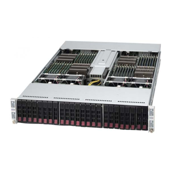
- Page 1 UPER ® A+ SERVER 2122TG-H6IBQRF 2122TG-H6RF USER'S MANUAL Revision 1.0c...
- Page 2 The information in this User’s Manual has been carefully reviewed and is believed to be accurate. The vendor assumes no responsibility for any inaccuracies that may be contained in this document, makes no commitment to update or to keep current the information in this manual, or to notify any person or organization of the updates.
- Page 3 Preface Preface About This Manual This manual is written for professional system integrators and PC technicians. It provides information for the installation and use of the A+ Server 2122TG-H6IBQRF/H6RF. Installation and maintainance should be performed by experienced technicians only. The A+ Server 2122TG-H6IBQRF/H6RF is a high-end server based on the SC217HQ-R1620BP 2U rackmount chassis and the dual processor H8DGT-HLIBQF/HLF serverboards.
- Page 4 A+ SERVER 2122TG-H6IBQRF/H6RF USER'S MANUAL Chapter 5: Advanced Serverboard Setup Chapter 5 provides detailed information on the H8DGT-HLIBQF/HLF serverboard, including the locations and functions of connections, headers and jumpers. Refer to this chapter when adding or removing processors or main memory and when reconfiguring the serverboard.
-
Page 5: Table Of Contents
Preface Table of Contents Chapter 1 Introduction Overview ......................1-1 Serverboard Features ..................1-2 Processors ...................... 1-2 Memory ......................1-2 SAS ........................ 1-2 PCI Expansion Slots ..................1-2 Onboard Controllers/Ports ................1-2 Graphics Controller ..................1-3 InfiniBand ......................1-3 Other Features ....................1-3 Server Chassis Features ................ - Page 6 A+ SERVER 2122TG-H6IBQRF/H6RF USER'S MANUAL Installing the System into a Rack ..............2-4 Identifying the Sections of the Rack Rails ............2-4 Locking Tabs ....................2-5 Releasing the Inner Rail ................. 2-5 Installing The Inner Rails on the Chassis ............2-6 Installing the Outer Rails on the Rack ............
- Page 7 Using the Adaptec RAID Utility ..............5-21 Installing the RAID Driver During OS Installation ......... 5-21 5-12 Installing Drivers .................... 5-22 Supero Doctor III ................... 5-23 5-13 Serverboard Battery ..................5-24 Chapter 6 Advanced Chassis Setup Static-Sensitive Devices .................. 6-1 Precautions .....................
- Page 8 A+ SERVER 2122TG-H6IBQRF/H6RF USER'S MANUAL Chapter 7 BIOS Introduction ...................... 7-1 Starting BIOS Setup Utility ................7-1 How To Change the Configuration Data ............7-1 Starting the Setup Utility ................. 7-2 Main Setup ...................... 7-2 Advanced Setup Configurations..............7-3 Security Menu ....................7-15 Boot Menu .....................
-
Page 9: Chapter 1 Introduction
Chapter 1: Introduction Chapter 1 Introduction Overview The A+ SERVER 2122TG-H6IBQRF/H6RF is a high-end server comprised of the SC217HQ-R1620BP 2U server chassis and four distinct computing nodes each with the H8DGT-HLIBQF/HLF dual processor serverboard. Please refer to our web site for information on operating systems that have been certified for use with the system (www.supermicro.com). -
Page 10: Serverboard Features
A+ SERVER 2122TG-H6IBQRF/H6RF USER'S MANUAL Serverboard Features At the heart of the A+ Server 2122TG-H6IBQRF/H6RF lies the H8DGT-HLIBQF/HLF, a dual processor serverboard based on the AMD SR5690/SP5100 chipset and designed to provide maximum performance. Up to four of these serverboards can be mounted in the SC217 chassis. -
Page 11: Graphics Controller
Chapter 1: Introduction Graphics Controller The H8DGT-HLIBQF/HLF features an integrated Matrox G200 graphics controller ® with 16 MB DDR2 memory. InfiniBand The 2122TG-H6IBQRF server includes a QDR (quad data rate) speed InfiniBand QSFP connector. InfiniBand is a scalable serial communications link intended for connecting processors with high-speed peripherals. -
Page 12: Front Control Panel
A+ SERVER 2122TG-H6IBQRF/H6RF USER'S MANUAL Front Control Panel SC217 models include four front panels on the handles of the chassis which control each of the systems. Each control panel on the A+ Server 2122TG-H6IBQRF/H6RF provides you with system monitoring and control for one server node. LEDs indicate system power, UID, HDD activity, network activity, system status and power supply failure. - Page 13 Chapter 1: Introduction Figure 1-1. AMD SR5690/SP5100 Chipset: System Block Diagram Note: This is a general block diagram. Please see Chapter 5 for details. HT3 Link DIMM 1A DIMM 1A (8+8)x(8+8)-6.4GT/s DIMM 2A DIMM 2A HT3 Link Socket G34 Socket G34 (8+8)x(8+8)-6.4GT/s CPU2 CPU1...
-
Page 14: Contacting Supermicro
A+ SERVER 2122TG-H6IBQRF/H6RF USER'S MANUAL Contacting Supermicro Headquarters Address: Super Micro Computer, Inc. 980 Rock Ave. San Jose, CA 95131 U.S.A. Tel: +1 (408) 503-8000 Fax: +1 (408) 503-8008 Email: marketing@supermicro.com (General Information) support@supermicro.com (Technical Support) Web Site: www.supermicro.com Europe Address: Super Micro Computer B.V. -
Page 15: Twin 2 : System Notes
Chapter 1: Introduction 2U Twin : System Notes As a 2U Twin configuration, the 2122TG-H6IBQRF/H6RF is a unique server system. With four system boards incorporated into a single chassis acting as four separate nodes, there are several points you should keep in mind. Nodes Each of the four serverboards act as a separate node in the system. - Page 16 A+ SERVER 2122TG-H6IBQRF/H6RF USER'S MANUAL Notes...
-
Page 17: Chapter 2 Server Installation
Chapter 2: Server Installation Chapter 2 Server Installation Overview This chapter provides a quick setup checklist to get your A+ Server 2122TG-H6IBQRF/H6RF up and running. Following these steps in the order given should enable you to have the system operational within a minimum amount of time. This quick setup assumes that your system has come to you with the processors and memory preinstalled. -
Page 18: Rack Precautions
A+ SERVER 2122TG-H6IBQRF/H6RF USER'S MANUAL • This product is for installation only in a Restricted Access Location (dedicated equipment rooms, service closets and the like). • This product is not suitable for use with visual display work place devices acccording to §2 of the the German Ordinance for Work with Visual Display Units. Rack Precautions Warning: To prevent bodily injury when mounting or servicing this unit in a rack, you must take special precautions to ensure that the system remains... -
Page 19: Rack Mounting Considerations
Chapter 2: Server Installation Rack Mounting Considerations Ambient Operating Temperature If installed in a closed or multi-unit rack assembly, the ambient operating temperature of the rack environment may be greater than the ambient temperature of the room. Therefore, consideration should be given to installing the equipment in an environment compatible with the manufacturer’s maximum rated ambient temperature (Tmra). -
Page 20: Installing The System Into A Rack
A+ SERVER 2122TG-H6IBQRF/H6RF USER'S MANUAL Installing the System into a Rack This section provides information on installing the chassis into a rack unit with the rails provided. There are a variety of rack units on the market, which may mean that the assembly procedure will differ slightly from the instructions provided. -
Page 21: Locking Tabs
Chapter 2: Server Installation Locking Tabs Each inner rail has a locking tab. This tab locks the chassis into place when installed and pushed fully into the rack. These tabs also lock the chassis in place when fully extended from the rack. This prevents the server from coming completely out of the rack when when the chassis is pulled out for servicing. -
Page 22: Installing The Inner Rails On The Chassis
A+ SERVER 2122TG-H6IBQRF/H6RF USER'S MANUAL Installing The Inner Rails on the Chassis To install the inner rails, use the procedure below. Installing the Inner Rails (Figure 2-3 and Figure 2-4) 1. Confirm that the left and right inner rails have been correctly identified. Place the inner rail firmly against the side of the chassis, aligning the hooks on the side of the chassis with the holes in the inner rail. -
Page 23: Installing The Outer Rails On The Rack
Chapter 2: Server Installation Installing the Outer Rails on the Rack Use the procedure below to install the outer rails onto the rack. Installing the Outer Rails (Figure 2-5) 1. Press upward on the locking tab at the rear end of the middle rail. 2. -
Page 24: Standard Chassis Installation
A+ SERVER 2122TG-H6IBQRF/H6RF USER'S MANUAL Standard Chassis Installation Stability hazard. The rack stabilizing mechanism must be in place, or the rack must be bolted to the floor before you slide the unit out for servicing. Failure to stabilize the rack can cause the rack to tip over. Installing the Chassis into a Rack (Figure 2-6) 1. -
Page 25: Checking The Serverboard Setup
Chapter 2: Server Installation Checking the Serverboard Setup After you install the A+ Server 2122TG-H6IBQRF/H6RF in the rack, you will need to open the unit to make sure the serverboard is properly installed and all the connections have been made. Before operating the SC217 chassis for the first time, it is important to remove the protective film covering the top of the chassis, in order to allow for proper ventilation and cooling. -
Page 26: Checking The Drive Bay Setup
A+ SERVER 2122TG-H6IBQRF/H6RF USER'S MANUAL Checking the Components and Setup • You may have one or two processors already installed into the serverboard. Each processor needs its own heat sink. See Chapter 5 for instructions on processor and heat sink installation. •... -
Page 27: Chapter 3 System Interface
Chapter 3: System Interface Chapter 3 System Interface Overview There are several LEDs on the control panel and on the drive carriers to keep you constantly informed of the overall status of the system. SC217 chassis models include four front panels on the handles of the chassis which control each of the systems. -
Page 28: Control Panel Button
A+ SERVER 2122TG-H6IBQRF/H6RF USER'S MANUAL Control Panel Button Power: The main power button on each of the four control panels is used to apply or remove power from the power supply to each of the four systems in the chassis. Turning power to the system off with this button removes the main power, but keeps standby power supplied to the system. -
Page 29: Drive Carrier Leds
Chapter 3: System Interface NIC: Indicates network activity on either LAN1 or LAN2 when flashing.. Drive Carrier LEDs The SC217 chassis uses SAS/SATA drives. SAS/SATA Drives Each drive carrier has two LEDs. • Green: Each drive carrier has a green LED. When illuminated, this green LED (on the front of the SAS/SATA drive carrier) indicates drive activity. - Page 30 A+ SERVER 2122TG-H6IBQRF/H6RF USER'S MANUAL Notes...
- Page 31 Chapter 4: Warning Statements for AC Systems Chapter 4 Standardized Warning Statements for AC Systems About Standardized Warning Statements The following statements are industry standard warnings, provided to warn the user of situations which have the potential for bodily injury. Should you have questions or experience difficulty, contact Supermicro's Technical Support department for assistance.
- Page 32 A+ SERVER 2122TG-H6IBQRF/H6RF USER'S MANUAL Warnung WICHTIGE SICHERHEITSHINWEISE Dieses Warnsymbol bedeutet Gefahr. Sie befinden sich in einer Situation, die zu Verletzungen führen kann. Machen Sie sich vor der Arbeit mit Geräten mit den Gefahren elektrischer Schaltungen und den üblichen Verfahren zur Vorbeugung vor Unfällen vertraut.
- Page 33 Warning Statements for AC Systems جسذٌة اصابة ًتتسبب ف حالة ٌوكي أى ًاًك ف خطز ًٌٌع هذا الزهز !تحذٌز الذوائز بالوخاطز الٌاجوة عي ي على علن ، ك هعذات تعول على أي قبل أى الكهزبائٍة حىادث أي وقىع وٌع ل الىقائٍة...
- Page 34 A+ SERVER 2122TG-H6IBQRF/H6RF USER'S MANUAL Installation Instructions Warning! Read the installation instructions before connecting the system to the power source. 設置手順書 システムを電源に接続する前に、 設置手順書をお読み下さい。 警告 将此系统连接电源前,请先阅读安装说明。 警告 將系統與電源連接前,請先閱讀安裝說明。 Warnung Vor dem Anschließen des Systems an die Stromquelle die Installationsanweisungen lesen. ¡Advertencia! Lea las instrucciones de instalación antes de conectar el sistema a la red de alimentación.
- Page 35 Chapter 4: Warning Statements for AC Systems Circuit Breaker Warning! This product relies on the building's installation for short-circuit (overcurrent) protection. Ensure that the protective device is rated not greater than: 250 V, 20 A. サーキッ ト ・ ブレーカー この製品は、 短絡 (過電流) 保護装置がある建物での設置を前提としています。 保護装置の定格が250 V、...
- Page 36 A+ SERVER 2122TG-H6IBQRF/H6RF USER'S MANUAL 경고! 이 제품은 전원의 단락(과전류)방지에 대해서 전적으로 건물의 관련 설비에 의존합니다. 보호장치의 정격이 반드시 250V(볼트), 20A(암페어)를 초과하지 않도록 해야 합니다. Waarschuwing Dit product is afhankelijk van de kortsluitbeveiliging (overspanning) van uw electrische installatie. Controleer of het beveiligde aparaat niet groter gedimensioneerd is dan 220V, 20A.
- Page 37 Chapter 4: Warning Statements for AC Systems ¡Advertencia! El sistema debe ser disconnected de todas las fuentes de energía y del cable eléctrico quitado de los módulos de fuente de alimentación antes de tener acceso el interior del chasis para instalar o para quitar componentes de sistema. Attention Le système doit être débranché...
- Page 38 A+ SERVER 2122TG-H6IBQRF/H6RF USER'S MANUAL Equipment Installation Warning! Only trained and qualified personnel should be allowed to install, replace, or service this equipment. 機器の設置 トレーニングを受け認定された人だけがこの装置の設置、 交換、 またはサービスを許可 されています。 警告 只有经过培训且具有资格的人员才能进行此设备的安装、更换和维修。 警告 只有經過受訓且具資格人員才可安裝、更換與維修此設備。 Warnung Das Installieren, Ersetzen oder Bedienen dieser Ausrüstung sollte nur geschultem, qualifiziertem Personal gestattet werden.
- Page 39 Chapter 4: Warning Statements for AC Systems Waarschuwing Deze apparatuur mag alleen worden geïnstalleerd, vervangen of hersteld door geschoold en gekwalificeerd personeel. Restricted Area Warning! This unit is intended for installation in restricted access areas. A restricted access area can be accessed only through the use of a special tool, lock and key, or other means of security.
- Page 40 A+ SERVER 2122TG-H6IBQRF/H6RF USER'S MANUAL אזור עם גישה מוגבלת !אזהרה יש להתקין את היחידה באזורים שיש בהם הגבלת גישה. הגישה ניתנת בעזרת .)'כלי אבטחה בלבד (מפתח, מנעול וכד محظورة مناطق ٍنتركُبها ف هذه انىحذة تخصيص تم ،أداة خاصت من خالل استخذاو فقط...
- Page 41 Chapter 4: Warning Statements for AC Systems Warnung Bei Einsetzen einer falschen Batterie besteht Explosionsgefahr. Ersetzen Sie die Batterie nur durch den gleichen oder vom Hersteller empfohlenen Batterietyp. Entsorgen Sie die benutzten Batterien nach den Anweisungen des Herstellers. Attention Danger d'explosion si la pile n'est pas remplacée correctement. Ne la remplacer que par une pile de type semblable ou équivalent, recommandée par le fabricant.
- Page 42 A+ SERVER 2122TG-H6IBQRF/H6RF USER'S MANUAL Redundant Power Supplies Warning! This unit might have more than one power supply connection. All connections must be removed to de-energize the unit. 冗長電源装置 このユニッ トは複数の電源装置が接続されている場合があります。 ユニッ トの電源を切るためには、 すべての接続を取り外さなければなりません。 警告 此部件连接的电源可能不止一个,必须将所有电源断开才能停止给该部件供电。 警告 此裝置連接的電源可能不只一個,必須切斷所有電源才能停止對該裝置的供電。 Warnung Dieses Gerät kann mehr als eine Stromzufuhr haben. Um sicherzustellen, dass der Einheit kein trom zugeführt wird, müssen alle Verbindungen entfernt werden.
- Page 43 Chapter 4: Warning Statements for AC Systems امداد الطاقة بوحدات عدة اتصاالت جهاز ال يكون لهذا قد الكهرباء عن وحدة ال لعسل كافة االتصاالت يجب إزالة 경고! 이 장치에는 한 개 이상의 전원 공급 단자가 연결되어 있을 수 있습니다. 이 장치에 전원을...
- Page 44 A+ SERVER 2122TG-H6IBQRF/H6RF USER'S MANUAL מתח בפנל האחורי !הרה אז קיימת סכנת מתח בפנל האחורי בזמן תפעול המערכת. יש להיזהר במהלך .העבודה اللىحة أوالطاقة المىجىدة على التيار الكهزبائي مه خطز هناك هذا الجهاس خدمة كه حذرا عند يعمل النظام عندما يكىن 경고! 시스템이...
- Page 45 Chapter 4: Warning Statements for AC Systems Attention L'équipement doit être installé conformément aux normes électriques nationales et locales. תיאום חוקי החשמל הארצי !אזהרה הציוד חייבת להיות תואמת לחוקי החשמל המקומיים והארציים התקנת المتعلقة المحلية والىطىية قىاويه يجب أن يمتثل لل الكهربائية...
- Page 46 A+ SERVER 2122TG-H6IBQRF/H6RF USER'S MANUAL ¡Advertencia! Al deshacerse por completo de este producto debe seguir todas las leyes y reglamentos nacionales. Attention La mise au rebut ou le recyclage de ce produit sont généralement soumis à des lois et/ou directives de respect de l'environnement. Renseignez-vous auprès de l'organisme compétent.
- Page 47 Chapter 4: Warning Statements for AC Systems 警告 當您從機架移除風扇裝置,風扇可能仍在轉動。小心不要將手指、螺絲起子和其他 物品太靠近風扇。 Warnung Die Lüfter drehen sich u. U. noch, wenn die Lüfterbaugruppe aus dem Chassis genommen wird. Halten Sie Finger, Schraubendreher und andere Gegenstände von den Öffnungen des Lüftergehäuses entfernt. ¡Advertencia! Los ventiladores podran dar vuelta cuando usted quite ell montaje del ventilador del chasis.
- Page 48 A+ SERVER 2122TG-H6IBQRF/H6RF USER'S MANUAL Power Cable and AC Adapter Warning! When installing the product, use the provided or designated connection cables, power cables and AC adaptors. Using any other cables and adaptors could cause a malfunction or a fire. Electrical Appliance and Material Safety Law prohibits the use of UL or CSA -certified cables (that have UL/CSA shown on the code) for any other electrical devices than products designated by Supermicro only.
- Page 49 Chapter 4: Warning Statements for AC Systems Attention Lors de l'installation du produit, utilisez les bables de connection fournis ou désigné. L'utilisation d'autres cables et adaptateurs peut provoquer un dysfonctionnement ou un incendie. Appareils électroménagers et de loi sur la sécurité Matériel interdit l'utilisation de UL ou CSA câbles certifiés qui ont UL ou CSA indiqué...
- Page 50 A+ SERVER 2122TG-H6IBQRF/H6RF USER'S MANUAL Notes 4-20...
-
Page 51: Chapter 5 Advanced Serverboard Setup
Chapter 5: Advanced Serverboard Setup Chapter 5 Advanced Serverboard Setup This chapter covers the steps required to install the H8DGT-HLIBQF/HLF serverboard into the chassis, connect the data and power cables and install add-on cards. All serverboard jumpers and connections are also described. A layout and quick reference chart are included in this chapter for your reference. - Page 52 A+ SERVER 2122TG-H6IBQRF/H6RF USER'S MANUAL Motherboard Installation This section explains the first step of physically mounting the H8DCT-HLN4F into the SC827 chassis. The 2122TG-H6IBQRF/H6RF is a highly complicated system. It is recommended that motherboard removal/installation be done by a Supermicro trained technician.
-
Page 53: I/O Port Connections
Chapter 5: Advanced Serverboard Setup I/O Port Connections The I/O ports are color coded to make setting up your system easier. See Figure 5-1 below for the colors and locations of the various I/O ports. Figure 5-1. I/O Port Locations and Definitions Rear I/O Ports 1. -
Page 54: Processor And Heatsink Installation
A+ SERVER 2122TG-H6IBQRF/H6RF USER'S MANUAL Processor and Heatsink Installation Notes: • When handling the processor, avoid placing direct pressure on the label area of the fan. Also, do not place the serverboard on a conductive surface, which can damage the BIOS battery and prevent the system from booting up. •... - Page 55 Chapter 5: Advanced Serverboard Setup 3. Use your thumb and your index finger to hold the CPU. Locate and align pin 1 of the CPU socket with pin 1 of the CPU. Both are marked with a triangle. Triangle 4. Align pin 1 of the CPU with pin 1 of the socket.
-
Page 56: Installing A Cpu Heatsink
A+ SERVER 2122TG-H6IBQRF/H6RF USER'S MANUAL Installing a CPU Heatsink 1. Remove power from the system and unplug the AC power cord from the power supply. 2. Do not apply any thermal grease to the heatsink or the CPU die; Screw #1 Screw #2 the required amount has already been applied. -
Page 57: Removing The Heatsink
Chapter 5: Advanced Serverboard Setup Removing the Heatsink Caution: We do not recommend that the CPU or the heatsink be removed. However, if you do need to uninstall the heatsink, please follow the instructions below to prevent damage to the CPU or the CPU socket. 1. -
Page 58: Installing Memory
A+ SERVER 2122TG-H6IBQRF/H6RF USER'S MANUAL Installing Memory Caution: Exercise extreme care when installing or removing DIMM modules to prevent any possible damage. Installing Memory 1. Insert each memory module vertically into its slot, paying attention to the notch along the bottom of the module to prevent inserting the module incorrectly (see Figure 5-3). -
Page 59: Dimm Module Population Configuration
Chapter 5: Advanced Serverboard Setup Figure 5-3. DIMM Installation Notch Notch To Install: Insert module vertically and press down until it snaps into place. Pay attention to the alignment notch at the bottom. Front View To Remove: Use your thumbs to gently push the release tabs near both ends of the module. -
Page 60: Pci Expansion Cards
A+ SERVER 2122TG-H6IBQRF/H6RF USER'S MANUAL Possible System Memory Allocation & Availability System Device Size Physical Memory Available (4 GB Total System Memory) Firmware Hub flash memory (System BIOS) 1 MB 3.99 GB Local APIC 4 KB 3.99 GB Area Reserved for the chipset 2 MB 3.99 GB I/O APIC (4 Kbytes) -
Page 61: Serverboard Details
Chapter 5: Advanced Serverboard Setup Serverboard Details Figure 5-4. H8DGT-HLIBQF/HLF Motherboard Layout (not drawn to scale) COM1 JIB1 JPG1 JPB1 JPL1 JWD1 SPEAKER SR5690 JBT1 SP5100 BATTERY CPU1 CPU2 Notes: Jumpers not indicated are for test purposes only. 5-11... -
Page 62: H8Dgt-Hlibqf/Hlf Quick Reference
A+ SERVER 2122TG-H6IBQRF/H6RF USER'S MANUAL H8DGT-HLIBQF/HLF Quick Reference Jumper Description Default Setting JBT1 CMOS Clear (See Section 5-9) JIB1 InfiniBand Enable/Disable (H8DGT-HLIBQF only) Pins 1-2 (Enabled) C1/JI C to PCI-E Slot Enable/Disable Both Closed (Enabled) JPB1 BMC Enable/Disable Pins 1-2 (Enabled) JPG1 VGA Enable/Disable Pins 1-2 (Enabled) -
Page 63: Connector Definitions
Chapter 5: Advanced Serverboard Setup Connector Definitions LAN1/2 (Ethernet Ports) Two Gigabit Ethernet ports (designated LAN1 and LAN2) are located beside the Serial port. Additionally, there is a dedicated LAN port for IPMI above the two rear USB ports. These Ethernet ports accept RJ45 type cables. - Page 64 A+ SERVER 2122TG-H6IBQRF/H6RF USER'S MANUAL Overheat LED Overheat LED Pin Definitions Connect an LED to the JOH1 header to (JOH1) provide warning of chassis overheating. See Pin# Definition the table on the right for pin definitions. 3.3V OH Active Unit Identifier Button UID Button Pin Definitions A Unit Identifier (UID) button is located on...
- Page 65 Chapter 5: Advanced Serverboard Setup JP3 Adapter Card Connector JP3 Adapter card connector slot provides front access to the power supply, serial ATA and Front Panel Control connections for the H8DGT series motherboards. Plug an Adapter card into this connector to use the functions indicated above.
-
Page 66: Jumper Settings
A+ SERVER 2122TG-H6IBQRF/H6RF USER'S MANUAL Jumper Settings Connector Pins Explanation of Jumpers To modify the operation of the motherboard, Jumper jumpers can be used to choose between optional settings. Jumpers create shorts between two pins to change the function Setting of the connector. - Page 67 Chapter 5: Advanced Serverboard Setup I2C to PCI-Express Slot C to PCI-Express Slot Jumper Settings C1/JI C2 allows you to enable the I C bus (JI2C1/JI2C2) to communicate with the PCI-Express slot. Jumper Setting Definition For the jumpers to work properly, please set Closed Enabled both jumpers to the same setting.
-
Page 68: 5-10 Onboard Indicators
A+ SERVER 2122TG-H6IBQRF/H6RF USER'S MANUAL 5-10 Onboard Indicators LAN LED (Connection Speed LAN LEDs Indicator) The Ethernet ports (located beside the VGA LED Color Definition port) have two LEDs. On each Gb LAN port, 10 MHz one LED blinks to indicate activity while the Green 100 MHz other may be green, amber or off to indicate... - Page 69 Chapter 5: Advanced Serverboard Setup InfiniBand LED Indicators InfiniBand LED (LE2) Activity LED Two InfiniBand LED indicators (LE2/LE3) Color Status Definition are located near the InfiniBand port of the Green Solid InfiniBand Connected H8DGT-HLIBQF serverboard. The green No Connection LED (LE2) is the InfiniBand link LED while the yellow LED (LE3) indicates activity.
-
Page 70: 5-11 Enabling Sata Raid
A+ SERVER 2122TG-H6IBQRF/H6RF USER'S MANUAL 5-11 Enabling SATA RAID Now that the hardware is set up, you must install the operating system and the SATA RAID drivers, if you wish to use RAID with your SATA drives. The installation procedure differs depending on whether you wish to have the operating system installed on a RAID array or on a separate non-RAID drive. -
Page 71: Enabling Sata Raid In The Bios
Chapter 5: Advanced Serverboard Setup Enabling SATA RAID in the BIOS Before installing the Windows operating system, you must change some settings in the BIOS. Boot up the system and hit the <Delete> key to enter the BIOS Setup Utlility. After the setup utility loads, 1. - Page 72 A+ SERVER 2122TG-H6IBQRF/H6RF USER'S MANUAL Figure 5-6. DotHill RAID Utility Program Screen Figure 5-7. Adaptec RAID Utility Program Screen Using the DotHill and Adaptec RAID Utility The RAID Utility program allows you to define the drives you want to include in the RAID array and the mode and type of RAID.
-
Page 73: Installing The Raid Driver During Os Installation
Chapter 5: Advanced Serverboard Setup Installing the RAID Driver During OS Installation You may also use the procedure below to install the RAID driver during the Windows OS installation: 1. With the Windows OS installation CD-ROM in the CD drive, restart the system. - Page 74 A+ SERVER 2122TG-H6IBQRF/H6RF USER'S MANUAL Figure 5-8. Driver/Tool Installation Display Screen Note: Click the icons showing a hand writing on paper to view the readme files for each item. Click the computer icons to the right of these items to install each item (from top to the bottom) one at a time.
- Page 75 Chapter 5: Advanced Serverboard Setup Figure 5-9. SuperDoctor III Interface Display Screen (Health Information) Figure 5-10. SuperDoctor III Interface Display Screen (Remote Control) 5-25...
-
Page 76: 5-13 Serverboard Battery
A+ SERVER 2122TG-H6IBQRF/H6RF USER'S MANUAL 5-13 Serverboard Battery Caution: There is a danger of explosion if the onboard battery is installed upside down, which will reverse its polarites (see Figure 5-11). This battery must be replaced only with the same or an equivalent type recommended by the manufacturer (CR2032). -
Page 77: Chapter 6 Advanced Chassis Setup
Chapter 6: Advanced Chassis Setup Chapter 6 Advanced Chassis Setup This chapter covers the steps required to install components and perform maintenance on the SC217HQ-R1620BP chassis. For component installation, follow the steps in the order given to eliminate the most common problems encountered. If some steps are unnecessary, skip ahead to the step that follows. -
Page 78: Control Panel
A+ SERVER 2122TG-H6IBQRF/H6RF USER'S MANUAL Figure 6-1. Front and Rear Chassis Views Control Panel Control Panel Control Panel Control Panel SAS/SATA Drives (24) COM1 Port VGA Port USB Ports Infiniband Port IPMI LAN Port Ethernet Ports Control Panel The control panel (located on the front of the chassis) must be connected to the chassis backplane connector on the serverboard to provide you with system status indications. -
Page 79: Chassis Cover
Chapter 6: Advanced Chassis Setup Chassis Cover Before operating the SC217 chassis for the first time, it is important to remove the protective film covering the top of the chassis, in order to allow for proper ventilation and cooling. Removing the Chassis Cover and Protective Film (Figure 6-2) 1. -
Page 80: Air Shrouds
A+ SERVER 2122TG-H6IBQRF/H6RF USER'S MANUAL Air Shrouds Air shrouds concentrate airflow to maximize fan efficiency. The SC217 chassis requires air shrouds for each motherboard node. Air shrouds vary depending upon the motherboard used. See the illustrations below. Installing an Air Shroud (Figure 6-3) 1. -
Page 81: System Fans
Chapter 6: Advanced Chassis Setup System Fans Four fans provide cooling for the chassis. These fans circulate air through the chassis as a means of lowering the chassis internal temperature. They system fans are easy to change modules. There is no need to uninstall any other parts inside the system when replacing fans, and no tools are required for installation. - Page 82 A+ SERVER 2122TG-H6IBQRF/H6RF USER'S MANUAL 5. Place the replacement fan into the vacant space in the housing while making sure the arrows on the top of the fan (indicating air direction) point in the same direction as the arrows on the other fans (see Figure 6-4). Figure 6-4.
- Page 83 Chapter 6: Advanced Chassis Setup 6. Put the fan back into the chassis and reconnect the cable (Figure 6-5). Figure 6-5. System Fan Placement 7. Confirm that the fan is working properly before replacing the chassis cover.
-
Page 84: Removing And Installing The Backplane
A+ SERVER 2122TG-H6IBQRF/H6RF USER'S MANUAL Removing and Installing the Backplane The SC217 chassis backplane is located behind the hard drives and in front of the front system fans. Although backplane failure rarely occurs, in the event of a backplane failure, follow the instructions below. Removing the Backplane Removing the Backplane from the Chassis 1. - Page 85 Chapter 6: Advanced Chassis Setup 6. Loosen the three screws in the spring bar, located on the floor of the chassis, indicated by the arrows below (Figure 6-7). 7. Remove the side screw from the side of the chassis. Figure 6-7. Loosening the Spring Bar Screws in the Floor of the Chassis 8.
-
Page 86: Installing The Backplane
A+ SERVER 2122TG-H6IBQRF/H6RF USER'S MANUAL Installing the Backplane Installing the Backplane into the Chassis (Figure 6-9) 1. Ensure that all of the hard drive carriers have been removed from the bays in the front of the chassis and that the spring bar has been loosened as directed in the previous section. -
Page 87: Installing The Motherboard
Chapter 6: Advanced Chassis Setup Installing the Motherboard I/O Shield The I/O shield holds the motherboard ports in place (Figure 6-10). The I/O shield does not require installation. Figure 6-10. I/O Shield Placement I/O Shields Permanent and Optional Standoffs Standoffs prevent short circuits by creating space between the motherboard and the chassis surface. - Page 88 A+ SERVER 2122TG-H6IBQRF/H6RF USER'S MANUAL 5. Make sure that the I/O ports on the serverboard align properly with their respective holes in the I/O shield at the back of the chassis. 6. Lay the motherboard in the node drawer aligning the standoffs with the motherboard.
-
Page 89: Adapter Card Replacement
Chapter 6: Advanced Chassis Setup Adapter Card Replacement Each motherboard drawer comes equipped with an adapter card which plugs into the backplane. In the unlikely event that the adapter card needs to be replaced, installation requires only a Phillips head screwdriver. Removing the Adapter Card (Figure 6-12) 1. -
Page 90: Add-On Card/Expansion Slot Setup
A+ SERVER 2122TG-H6IBQRF/H6RF USER'S MANUAL Add-on Card/Expansion Slot Setup The SC217 chassis supports one low-profile expansion slot for each node, for a total of four slots in the chassis (Figure 6-13). To install a low-profile PCI card, follow the following instructions. Figure 6-13. - Page 91 Chapter 6: Advanced Chassis Setup Installing Add-on Cards (Figure 6-14) 1. Disconnect the chassis from any power source, lay the chassis on a flat surface, and open the chassis cover. 2. Pull open the add-on card slot clip in the rear of the chassis. 3.
- Page 92 A+ SERVER 2122TG-H6IBQRF/H6RF USER'S MANUAL Hard Disk Drives The SC217 chassis features 24 drive bays that are accessable for drive replacement from the front of the chassis. The drives are mounted in drive carriers to simplify their installation and removal. These carriers also help promote proper airflow for the drive bays.
- Page 93 Chapter 6: Advanced Chassis Setup Removing Hard Drive Carriers from the Chassis 1. Press the release button on the drive carrier. This extends the drive bay handle. 2. Use the handle to pull the drive out of the chassis (Figure 6-16). 3.
- Page 94 A+ SERVER 2122TG-H6IBQRF/H6RF USER'S MANUAL Figure 6-17. Removing a Dummy Drive from Carrier Dummy Drive Drive Carrier Installing a Drive into the Carrier 1. Install a new drive into the carrier with the printed circuit board side facing down so that the mounting holes in the drive align with those in the carrier. 2.
-
Page 95: 6-10 Power Supply
Chapter 6: Advanced Chassis Setup 6-10 Power Supply The SC217 chassis includes a 1620 watt power supply. It automatically senses and operates at the proper voltage between 100v to 240v. An amber light on the power supply is illuminated when the system power is off. A green light indicates that the power supply is operating. - Page 96 A+ SERVER 2122TG-H6IBQRF/H6RF USER'S MANUAL Notes 6-20...
-
Page 97: Chapter 7 Bios
Chapter 7: BIOS Chapter 7 BIOS Introduction This chapter describes the AMI BIOS Setup Utility for the H8DGT-HLIBQF/HLF-F. The 16 Mb AMI BIOS® is stored in a Flash EEPROM and can be easily updated. This chapter describes the basic navigation of the AMI BIOS Setup Utility setup screens. -
Page 98: Starting The Setup Utility
A+ SERVER 2122TG-H6IBQRF/H6RF USER'S MANUAL Starting the Setup Utility Normally, the only visible Power-On Self-Test (POST) routine is the memory test. As the memory is being tested, press the <Delete> key to enter the main menu of the AMI BIOS Setup Utility. From the main menu, you can access the other setup screens. -
Page 99: Advanced Setup Configurations
Chapter 7: BIOS • Logical Count: This item displays the number of CPU Cores installed in your system as detected by the BIOS. • Micro_code Revision: This item displays the revision number of the BIOS Micro_code used in your system. System Memory This displays the size of memory available in the system: •... - Page 100 A+ SERVER 2122TG-H6IBQRF/H6RF USER'S MANUAL Quiet Boot If Disabled, normal POST messages will be displayed on boot-up. If Enabled, this display the OEM logo instead of POST messages. Add On ROM Display Mode This option sets the display mode for Option ROM. The options are Force BIOS or Keep Current.
- Page 101 Chapter 7: BIOS Processor & Clock Options Configuration CPU Configuration This displays static information on the Module Version, AGESA Version, Physical Count and Logical Count for the system's processor(s) and clock. CPU Information This setting is used to select which physical CPU's information to display. Options include Processor 0 or Processor 1.
- Page 102 A+ SERVER 2122TG-H6IBQRF/H6RF USER'S MANUAL Clock Speed Spectrum This option enables or disables spread spectrum modulation. Advanced Chipset Control Configuration NorthBridge Configuration Memory Configuration Bank Interleaving Select Auto to automatically enable a bank-interleaving memory scheme when this function is supported by the processor. The options are Auto and Disabled.
- Page 103 Chapter 7: BIOS DRAM ECC Enable This setting allows hardware to report and correct memory errors automatically, maintaining system integrity. Options are Enabled or Disabled. DRAM Timing Configuration DRAM Timing Config This setting specifies the DRAM timing configuration. Options are Auto and Manual.
- Page 104 A+ SERVER 2122TG-H6IBQRF/H6RF USER'S MANUAL OnChip SATA Type Use this setting to set the OnChip SATA type. Options include Native IDE, RAID, AMD_AHCI and Legacy IDE. RAID Codebase This submenu appears when you choose "RAID" from the "OnChip SATA Type" setting above. This setting allows you to select the codebase for your RAID setup.
- Page 105 Chapter 7: BIOS mode 3, which has a data transfer rate of 11.1 MBs. Select 4 to allow BIOS to use PIO mode 4, which has a data transfer rate of 16.6 MBs. This setting generally works with all hard disk drives manufactured after 1999. For other disk drives, such as IDE CD-ROM drives, check the specifications of the drive.
- Page 106 A+ SERVER 2122TG-H6IBQRF/H6RF USER'S MANUAL PCI IDE Busmaster Use this setting to Enable or Disable BIOS enabled uses of PCI Busmastering for reading or writing to IDE drives. Onboard InfiniBand Controller This option Enables or Disables the onboard InfiniBand controller. Onboard VGA Controller This option Enables or Disables the onboard VGA controller.
- Page 107 Chapter 7: BIOS I/O port address and IRQ 4 for the interrupt address. Options include Disabled, 3F8/IRQ4, 3E8/IRQ4 and 2E8/IRQ3 Serial 2 Address This option specifies the base I/O port address and Interrupt Request address of serial port 2. Select "Disabled" to prevent the serial port from accessing any system resources.
- Page 108 A+ SERVER 2122TG-H6IBQRF/H6RF USER'S MANUAL Terminal Type Selects the type of the target terminal. Options are ANSI, VT100 and VT-UTF8. VT-UTF8 Combo Key Support Allows you to Enable or Disable VT-UTF8 combination key support for ANSI/ VT100 terminals. Sredir Memory Display Delay Use this setting to set the delay in seconds to display memory information.
- Page 109 Chapter 7: BIOS Headless Mode Use this setting to Enable or Disable headless operation mode through ACPI. ACPI Version Features Use this setting the determine which ACPI version to use. Options are ACPI v1.0, ACPI v2.0 and ACPI v3.0. IPMI Configuration This menu shows static information about the IPMI firmware revision and status of the BMC, as well as options for IPMI configuration.
- Page 110 A+ SERVER 2122TG-H6IBQRF/H6RF USER'S MANUAL IP Address This submenu sets the IP address source as either Static or DHCP. Selecting Static allows you to manually set the IP Address, Subnet Mask and Gateway Address. In the field provided here enter the IP address in the decimal form of xxx.xxx. xxx.xxx with xxx having a value of less than 256 and in decimal form only The IP address and current IP address in the BMC are shown.
-
Page 111: Security Menu
Chapter 7: BIOS SR56x0 (RD890S) PCIE Error Log This setting allows you set an error log ofr PCIE errors. Options include Yes or No. Security Menu AMI BIOS provides a Supervisor and a User password. If you use both passwords, the Supervisor password must be set first. -
Page 112: Exit Menu
A+ SERVER 2122TG-H6IBQRF/H6RF USER'S MANUAL Retry Boot Devices This option allows you to retry boot devices. Options include Enabled and Disabled. Exit Menu Select the Exit tab from AMI BIOS Setup Utility screen to enter the Exit BIOS Setup screen. Save Changes and Exit When you have completed the system configuration changes, select this option to leave BIOS Setup and reboot the computer, so the new system configuration... -
Page 113: Appendix A Bios Error Beep Codes
Appendix A: BIOS Error Beep Codes Appendix A BIOS Error Beep Codes During the POST (Power-On Self-Test) routines, which are performed each time the system is powered on, errors may occur. Non-fatal errors are those which, in most cases, allow the system to continue the boot-up process. - Page 114 A+ SERVER 2122TG-H6IBQRF/H6RF USER'S MANUAL Notes...
-
Page 115: Appendix B System Specifications
Appendix B: System Specifications Appendix B System Specifications Note: Unless noted specifications apply to a complete system (all serverboards). Processors Dual AMD Opteron 6000 series processors (AMD Socket G34 type) Note: Both CPUs must be of the same type. Note: Please refer to our web site for a complete listing of supported processors. Note: Supports 6000 processors with Max ACP 80W (TDP 115W). - Page 116 A+ SERVER 2122TG-H6IBQRF/H6RF USER'S MANUAL Serverboard Four H8DGT-HLIBQF/HLF (Extended ATX form factor) Dimensions: (LxW) 6.78" x 16.64" (172 x 423 mm) Chassis SC217HQ-R1620BP (2U rackmount) Dimensions: (WxHxD) 17.25 x 3.47 x 28.5 in. (438 x 88 x 724 mm) Weight Gross (Bare Bone): 85 lbs.
- Page 117 Appendix B: System Specifications Regulatory Compliance Electromagnetic Emissions: FCC Class A, EN 55022 Class A, EN 61000-3-2/-3- 3, CISPR 22 Class A Electromagnetic Immunity: EN 55024/CISPR 24, (EN 61000-4-2, EN 61000-4-3, EN 61000-4-4, EN 61000-4-5, EN 61000-4-6, EN 61000-4-8, EN 61000-4-11) Safety: CSA/EN/IEC/UL 60950-1 Compliant, UL or CSA Listed (USA and Canada), CE Marking (Europe) California Best Management Practices Regulations for Perchlorate Materials:...
- Page 118 A+ SERVER 2122TG-H6IBQRF/H6RF USER'S MANUAL (continued from front) The products sold by Supermicro are not intended for and will not be used in life support systems, medical equipment, nuclear facilities or systems, aircraft, aircraft devices, aircraft/emergency communication devices or other critical systems whose failure to perform be reasonably expected to result in significant injury or loss of life or catastrophic property damage.