Cateye Strada Wireless Quick Start Manual
Hide thumbs
Also See for Strada Wireless:
- Quick start manual (2 pages) ,
- User manual (11 pages) ,
- Owner's manual (3 pages)
Advertisement
Quick Links
CATEYE STRADA WIRELESS
CATEYE STRADA WIRELESS
CATEYE STRADA WIRELESS
CYCLOCOMPUTER CC-RD300W
CYCLOCOMPUTER CC-RD300W
CYCLOCOMPUTER CC-RD300W
Before using the computer, please thoroughly read this manual and keep it for
Before using the computer, please thoroughly read this manual and keep it for
CATEYE STRADA WIRELESS
future reference.
future reference.
WARNING / CAUTION
WARNING / CAUTION
WARNING / CAUTION
CYCLOCOMPUTER CC-RD300W
• Do not concentrate on the computer while riding. Ride safely!
• Do not concentrate on the computer while riding. Ride safely!
• Do not concentrate on the computer while riding. Ride safely!
• Install the magnet, sensor, and bracket securely. Check these periodically.
• Install the magnet, sensor, and bracket securely. Check these periodically.
• Install the magnet, sensor, and bracket securely. Check these periodically.
• If a child swallows a battery, consult a doctor immediately.
• If a child swallows a battery, consult a doctor immediately.
• If a child swallows a battery, consult a doctor immediately.
• Do not leave the computer in direct sunlight for unnecessary or extended periods.
• Do not leave the computer in direct sunlight for unnecessary or extended periods.
• Do not leave the computer in direct sunlight for unnecessary or extended periods.
Before using the computer, please thoroughly read this manual and keep it for
• Do not disassemble the computer.
• Do not disassemble the computer.
• Do not disassemble the computer.
future reference.
• Do not drop the computer. Doing so may result in a computer malfunction or damage.
• Do not drop the computer. Doing so may result in a computer malfunction or damage.
• Do not drop the computer. Doing so may result in a computer malfunction or damage.
• When using the computer installed on the bracket, change the MODE by pressing on the three dots
• When using the computer installed on the bracket, change the MODE by pressing on the three dots
• When using the computer installed on the bracket, change the MODE by pressing on the three dots
WARNING / CAUTION
below the screen. Pressing hard on other areas can result in malfunction or damage to the computer.
below the screen.Pressing hard on other areas can result in malfunction or damage to the computer.
below the screen. Pressing hard on other areas can result in malfunction or damage to the computer.
• Do not concentrate on the computer while riding. Ride safely!
• Tighten the dial on the Flex-Tight bracket by hand only. Over-tightening can damage the bracket
• Tighten the dial on the Flex-Tight bracket by hand only. Over-tightening can damage the bracket
• Tighten the dial on the Flex-Tight bracket by hand only. Over-tightening can damage the bracket
• Install the magnet, sensor, and bracket securely. Check these periodically.
threads.
threads.
threads.
• If a child swallows a battery, consult a doctor immediately.
• When cleaning the computer, bracket and sensor, do not use thinners, benzene, or alcohol.
• When cleaning the computer, bracket and sensor, do not use thinners, benzene, or alcohol.
• When cleaning the computer, bracket and sensor, do not use thinners, benzene, or alcohol.
• Do not leave the computer in direct sunlight for unnecessary or extended periods.
• Dispose of used batteries according to local regulations.
• Risk of explosion if battery is replaced by an incorrect type. Dispose of used batteries
• Dispose of used batteries according to local regulations.
• Do not disassemble the computer.
• LCD screen may be distorted when viewed through polarized sunglass lenses.
• LCD screen may be distorted when viewed through polarized sunglass lenses.
according to local regulations.
• Do not drop the computer. Doing so may result in a computer malfunction or damage.
• LCD screen may be distorted when viewed through polarized sunglass lenses.
Wireless Sensor
Wireless Sensor
• When using the computer installed on the bracket, change the MODE by pressing on the three dots
below the screen. Pressing hard on other areas can result in malfunction or damage to the computer.
Wireless Sensor
The sensor was designed to receive signals within a maximum range of 70 cm, to reduce chance of
The sensor was designed to receive signals within a maximum range of 70 cm, to reduce chance of
• Tighten the dial on the Flex-Tight bracket by hand only. Over-tightening can damage the bracket
interference.
interference.
The sensor was designed to receive signals within a maximum range of 70 cm, to reduce chance of
threads.
When adjusting the wireless sensor, note the following:
When adjusting the wireless sensor, note the following:
interference.
• When cleaning the computer, bracket and sensor, do not use thinners, benzene, or alcohol.
• Signals cannot be received if the distance between the sensor and the computer is too great.
• Signals cannot be received if the distance between the sensor and the computer is too great.
When adjusting the wireless sensor, note the following:
• Dispose of used batteries according to local regulations.
• The transmission distance may be shorter due to low temperature or low battery.
• The transmission distance may be shorter due to low temperature or low battery.
• Signals cannot be received if the distance between the sensor and the computer is too great.
• LCD screen may be distorted when viewed through polarized sunglass lenses.
• Signals can be received only when the back of the computer is facing the sensor.
• Signals can be received only when the back of the computer is facing the sensor.
• The transmission distance may be shorter due to low temperature or low battery.
Interference may occur, resulting in incorrect data, if the computer is:
Interference may occur, resulting in incorrect data, if the computer is:
• Signals can be received only when the back of the computer is facing the sensor.
Wireless Sensor
• Near a TV, PC, radio, motor, or in a car or train.
• Near a TV, PC, radio, motor, or in a car or train.
Interference may occur, resulting in incorrect data, if the computer is:
The sensor was designed to receive signals within a maximum range of 70 cm, to reduce chance of
• Close to a railroad crossing, railway tracks, TV stations and/or radar base.
• Close to a railroad crossing, railway tracks, TV stations and/or radar base.
• Near a TV, PC, radio, motor, or in a car or train.
interference.
• Using with other wireless devices in close proximity.
• Using with other wireless devices in close proximity.
• Close to a railroad crossing, railway tracks, TV stations and/or radar base.
When adjusting the wireless sensor, note the following:
• Using with other wireless devices in close proximity.
• Signals cannot be received if the distance between the sensor and the computer is too great.
This device complies with Part 15 of the FCC Rules.Operation is subject to the following
This device complies with Part 15 of the FCC Rules.Operation is subject to the following
Frequency Band: 19.076 kHz
• The transmission distance may be shorter due to low temperature or low battery.
two conditions:(1)This device may not cause harmful interference,and (2)this device
two conditions:(1)This device may not cause harmful interference,and (2)this device
Maximum radio-frequency power: 0.912 uW
must accept any interference received,including interference that may cause undesired
must accept any interference received,including interference that may cause undesired
• Signals can be received only when the back of the computer is facing the sensor.
operation.
operation.
Hereby, CATEYE Co., Ltd. declares that the radio equipment type Wireless Cyclecomputer CC-RD300W &
Interference may occur, resulting in incorrect data, if the computer is:
Modifications The FCC requires the user to be notified that any changes or modifications
Modifications The FCC requires the user to be notified that any changes or modifications
SPD-01 SENSOR is in compliance with Directive 2014/53/EU.
• Near a TV, PC, radio, motor, or in a car or train.
made to this device that are not expressly approved by CatEye Co.,Ltd.May void the user
made to this device that are not expressly approved by CatEye Co.,Ltd.May void the user
The full text of the EU declaration of conformity is available at the following internet address:
• Close to a railroad crossing, railway tracks, TV stations and/or radar base.
's authority to operate the equipment.
's authority to operate the equipment.
cateye.com/doc
• Using with other wireless devices in close proximity.
Preparing the computer
Preparing the computer
This device complies with Part 15 of the FCC Rules.Operation is subject to the following
two conditions:(1)This device may not cause harmful interference,and (2)this device
must accept any interference received,including interference that may cause undesired
Battery case cover
Battery case cover
operation.
Modifications The FCC requires the user to be notified that any changes or modifications
made to this device that are not expressly approved by CatEye Co.,Ltd.May void the user
MENU
MENU
's authority to operate the equipment.
AC
AC
Preparing the computer
MODE
MODE
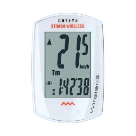
: Speed unit
: Speed unit
Battery case cover
: Wheel size icon
: Wheel size icon
(CC-RD300W)
: Sensor signal reception icon
: Sensor signal reception icon
MENU
1
1
AC
Clear all data (initialization)
Clear all data (initialization)
Press the AC button on the back.
Press the AC button on the back.
MODE
: Speed unit
: Wheel size icon
: Sensor signal reception icon
2
2
Select the desired speed units
Select the desired speed units
1
Clear all data (initialization)
Select "
Select "
" or "
" or "
".
".
Press the AC button on the back.
Register the
Register the
km/h ↔ mph
km/h ↔ mph
setting
setting
MENU
MENU
MENU
MENU
MODE
MODE
MODE
MODE
2
Select the desired speed units
3
3
Enter the tire circumference
Enter the tire circumference
Select "
" or "
".
Enter the tire circumference of your bicycle in mm.
Enter the tire circumference of your bicycle in mm.
Register the
* Refer to the tire circumference reference table.
* Refer to the tire circumference reference table.
km/h ↔ mph
setting
MODE
MODE
MENU
MENU
Move digits
Move digits
Increase
Increase
(by pressing
(by pressing
& holding)
& holding)
3
MENU
MENU
MENU
MENU
MODE
MODE
MODE
MODE
Enter the tire circumference
MODE
MODE
MODE
MODE
4
4
Enter the tire circumference of your bicycle in mm.
Set the clock
Set the clock
* Refer to the tire circumference reference table.
When MODE is pressed and held, "Displayed
When MODE is pressed and held, "Displayed
time", "Hour", and "Minute" will appear, in
time", "Hour", and "Minute" will appear, in
Move digits
Increase
(by pressing
this order.
this order.
& holding)
Switch the
Switch the
MENU
MENU
MODE
MODE
24h ↔ 12h,
24h ↔ 12h,
MODE
MODE
screen or
screen or
or increase
or increase
4
move digits
move digits
Set the clock
the value
the value
(by pressing
(by pressing
MENU
MENU
MENU
MENU
MODE
MODE
MODE
MODE
MODE
MODE
MODE
MODE
When MODE is pressed and held, "Displayed
& holding)
& holding)
time", "Hour", and "Minute" will appear, in
this order.
Switch the
24h ↔ 12h,
screen or
or increase
move digits
the value
(by pressing
MENU
MENU
MODE
MODE
MODE
MODE
& holding)
Tire circumference
Tire circumference
reference table
reference table
Tire size
Tire size
12 x 1.75
12 x 1.75
14 x 1.50
14 x 1.50
14 x 1.75
14 x 1.75
16 x 1.50
16 x 1.50
16 x 1.75
16 x 1.75
Tire circumference
18 x 1.50
18 x 1.50
18 x 1.75
18 x 1.75
reference table
20 x 1.75
20 x 1.75
When the computer is
When the computer is
Tire size
20 x 1-3/8
20 x 1-3/8
mounted on the bracket
mounted on the bracket
22 x 1-3/8
22 x 1-3/8
12 x 1.75
22 x 1-1/2
22 x 1-1/2
14 x 1.50
Push!
Push!
24 x 1
24 x 1
14 x 1.75
24 x 3/4 Tubular
24 x 3/4 Tubular
16 x 1.50
24 x 1-1/8
24 x 1-1/8
16 x 1.75
24 x 1-1/4
24 x 1-1/4
18 x 1.50
24 x 1.75
24 x 1.75
18 x 1.75
24 x 2.00
24 x 2.00
20 x 1.75
When the computer is
24 x 2.125
24 x 2.125
20 x 1-3/8
mounted on the bracket
26 x 7/8
26 x 7/8
22 x 1-3/8
26 x 1 ( 59 )
26 x 1 ( 59 )
22 x 1-1/2
Push!
26 x 1 ( 65 )
26 x 1 ( 65 )
24 x 1
26 x 1.25
26 x 1.25
24 x 3/4 Tubular
26 x 1-1/8
26 x 1-1/8
24 x 1-1/8
26 x 1-3/8
26 x 1-3/8
24 x 1-1/4
26 x 1-1/2
26 x 1-1/2
24 x 1.75
26 x 1.40
26 x 1.40
24 x 2.00
26 x 1.50
26 x 1.50
24 x 2.125
AC
AC
26 x 1.75
26 x 1.75
26 x 7/8
26 x 1 ( 59 )
26 x 1.95
26 x 1.95
26 x 2.00
26 x 1 ( 65 )
26 x 2.00
26 x 2.10
26 x 2.10
26 x 1.25
26 x 2.125
26 x 2.125
26 x 1-1/8
26 x 2.35
26 x 2.35
26 x 1-3/8
26 x 3.00
26 x 3.00
26 x 1-1/2
27 x 1
27 x 1
26 x 1.40
27 x 1-1/8
27 x 1-1/8
26 x 1.50
27 x 1-1/4
27 x 1-1/4
AC
26 x 1.75
27 x 1-3/8
26 x 1.95
27 x 1-3/8
650 x 20C
650 x 20C
26 x 2.00
650 x 23C
650 x 23C
26 x 2.10
650 x 35A
650 x 35A
26 x 2.125
650 x 38A
650 x 38A
26 x 2.35
650 x 38B
650 x 38B
26 x 3.00
700 x 18C
700 x 18C
27 x 1
700 x 19C
700 x 19C
27 x 1-1/8
700 x 20C
700 x 20C
27 x 1-1/4
700 x 23C
700 x 23C
27 x 1-3/8
Register
Register
700 x 25C
700 x 25C
650 x 20C
700 x 28C
700 x 28C
the setting
the setting
650 x 23C
700 x 30C
700 x 30C
650 x 35A
700 x 32C
700 x 32C
650 x 38A
700C Tubular
700C Tubular
650 x 38B
700 x 35C
700 x 35C
700 x 18C
700 x 38C
700 x 38C
700 x 19C
700 x 40C
700 x 40C
700 x 20C
29 x 2.1
29 x 2.1
700 x 23C
Register
29 x 2.3
29 x 2.3
700 x 25C
the setting
700 x 28C
Measure wheel circumference
Measure wheel circumference
700 x 30C
(L) of your bike
(L) of your bike
700 x 32C
To get the most accurate
To get the most accurate
700C Tubular
calibration do a wheel roll out.
calibration do a wheel roll out.
700 x 35C
With the valve stem
With the valve stem
700 x 38C
perpendicular to the ground,
perpendicular to the ground,
700 x 40C
mark the pavement at the valve
mark the pavement at the valve
29 x 2.1
stem. With the riders weight on
stem. With the riders weight on
29 x 2.3
the bike, roll the wheel one tire
the bike, roll the wheel one tire
Measure wheel circumference
revolution in a straight line and
revolution in a straight line and
(L) of your bike
mark the ground when the
mark the ground when the
To get the most accurate
valve stem is perpendicular to
valve stem is perpendicular to
calibration do a wheel roll out.
the ground again. Measure the
the ground again. Measure the
With the valve stem
distance in millimeters. This is
distance in millimeters. This is
perpendicular to the ground,
the most accurate wheel
the most accurate wheel
mark the pavement at the valve
calibration number.
calibration number.
stem. With the riders weight on
the bike, roll the wheel one tire
revolution in a straight line and
mark the ground when the
valve stem is perpendicular to
the ground again. Measure the
distance in millimeters. This is
the most accurate wheel
calibration number.
How to install the unit on your bicycle
How to install the unit on your bicycle
4
2
2
4
4
2
1
1
1
(SPD-01)
3
3
7
7
How to install the unit on your bicycle
7
3
2
4
1
Install the sensor and magnet
Install the sensor and magnet
3
7
A
A
The distance between the computer
The distance between the computer
and the sensor must not exceed the
and the sensor must not exceed the
transmission range of 70 cm. The back
transmission range of 70 cm. The back
of the computer must face the sensor.
of the computer must face the sensor.
Install the sensor and magnet
YES!
YES!
NO!
NO!
A
The distance between the computer
and the sensor must not exceed the
transmission range of 70 cm. The back
of the computer must face the sensor.
YES!
NO!
L (mm)
L (mm)
Max
Max
935
935
70 cm
70 cm
1020
1020
1055
1055
1185
1185
1195
1195
1340
1340
1350
1350
1515
1515
L (mm)
Max
1615
1615
1
1
Install the sensor
Install the sensor
1770
1770
935
70 cm
1785
1785
1020
1753
1753
1055
1785
1785
1185
1795
1795
4
4
1195
1905
1905
1340
1890
1890
1350
1925
1925
1515
6
6
1965
1965
1615
1
1920
1920
Install the sensor
1770
1913
1913
1785
1952
1952
1753
1953
1953
* Install the sensor as close to the upper
* Install the sensor as close to the upper
1785
1970
1970
4
1795
part of the front fork as possible.
part of the front fork as possible.
1905
2068
2068
2100
2100
1890
3
3
Attach the bracket to the stem or handlebar
Attach the bracket to the stem or handlebar
2005
2005
1925
6
2010
2010
1965
When attaching the bracket to the stem
When attaching the bracket to the stem
2023
2023
1920
2050
2050
1913
2055
2055
1952
2068
2068
1953
* Install the sensor as close to the upper
2
2
2070
2070
1970
1
1
part of the front fork as possible.
2083
2083
2068
2170
2170
2100
3
Attach the bracket to the stem or handlebar
2145
2145
2005
2155
2155
2010
When attaching the bracket to the stem
2161
2161
2023
2169
2050
2169
1938
1938
2055
Caution:
Caution:
1944
1944
2068
Make sure that the back of the computer faces the sensor.
Make sure that the back of the computer faces the sensor.
2
2090
2090
2070
1
2125
2125
2083
* The computer may not function appropriately on some
* The computer may not function appropriately on some
2105
2105
2170
stem if its back does not face the sensor as shown in
stem if its back does not face the sensor as shown in
2070
2070
2145
2080
2080
2155
2086
2086
When attaching the bracket to the handlebar
When attaching the bracket to the handlebar
2161
2096
2096
2169
2105
2105
1938
Caution:
2136
2136
1944
Make sure that the back of the computer faces the sensor.
2146
2146
2090
1
1
2
2
2155
2155
2125
* The computer may not function appropriately on some
2130
2130
2105
stem if its back does not face the sensor as shown in
2168
2168
2070
2180
2180
2080
2200
2200
2086
When attaching the bracket to the handlebar
2288
2288
2096
2326
2326
2105
2136
4
4
Remove/install the
Remove/install the
2146
2
1
computer
computer
2155
2130
Click
Click
2168
2180
2200
2288
2326
4
Remove/install the
computer
Click
* After installation, rotate the front wheel gently to check that the speed is displayed on the
* After installation, rotate the front wheel gently to check that the speed is displayed on the
computer. If the speed is not displayed, check that conditions
computer. If the speed is not displayed, check that conditions
been done appropriately.
been done appropriately.
L mm
L mm
* After installation, rotate the front wheel gently to check that the speed is displayed on the
computer. If the speed is not displayed, check that conditions
been done appropriately.
L mm
U.S. Pat. Nos. 5236759/6957926 Design Patented
U.S. Pat. Nos. 5236759/6957926 Pat./Design Pat. Pending
U.S. Pat. Nos. 5236759/6957926 Pat./Design Pat. Pending
Copyright© 2017 CATEYE Co., Ltd.
Copyright© 2011 CATEYE Co., Ltd.
Copyright© 2011 CATEYE Co., Ltd.
CCRD300W-171227
CCRD3W-110930 066600542 6
CCRD3W-110930 066600542 6
1 Bracket band
1 Bracket band
5
5
5
2 Bracket
2 Bracket
U.S. Pat. Nos. 5236759/6957926 Pat./Design Pat. Pending
Copyright© 2011 CATEYE Co., Ltd.
6
Nut
Nut
3
3
6
6
CCRD3W-110930 066600542 6
Speed sensor
Speed sensor
4
4
5 Magnet
5 Magnet
6 Sensor rubber pad
6 Sensor rubber pad
7 Bracket rubber pad
7 Bracket rubber pad
1 Bracket band
8
8
5
8
8 Nylon ties (x2)
8 Nylon ties (x2)
2 Bracket
3
Nut
6
Speed sensor
4
5 Magnet
6 Sensor rubber pad
B
B
7 Bracket rubber pad
The magnet
The magnet
8
8 Nylon ties (x2)
must pass
must pass
through the
through the
sensor zone.
sensor zone.
B
The magnet
Inside of right front fork
Inside of right front fork
must pass
through the
C
C
sensor zone.
The clearance
The clearance
between the
between the
5
5
sensor surface
sensor surface
and the magnet
and the magnet
Inside of right front fork
must not
must not
exceed 5 mm.
exceed 5 mm.
C
The clearance
between the
5
sensor surface
Inside of right front fork
Inside of right front fork
and the magnet
Pull
Pull
must not
securely
securely
exceed 5 mm.
8
8
Inside of right front fork
Pull
securely
8
Stem
Stem
7
7
Stem
7
.
.
A
A
Handlebar
Handlebar
7
7
.
A
Handlebar
7
* For wing type handlebar or oversized
* For wing type handlebar or oversized
While supporting it by hand,
While supporting it by hand,
stem, bracket can be mounted using
stem, bracket can be mounted using
the Bracket Holder and nylon ties.
the Bracket Holder and nylon ties.
(Option)
(Option)
* For wing type handlebar or oversized
While supporting it by hand,
push it out as if lifting the front up
push it out as if lifting the front up
stem, bracket can be mounted using
the Bracket Holder and nylon ties.
(Option)
push it out as if lifting the front up
ENG
ENG
ENG
10
ENG
Sensor zone
Sensor zone
5
5
4
4
Sensor zone
4
4
5
4
4
2
2
Install the magnet
Install the magnet
Spoke
Spoke
5
5
2
Install the magnet
Toward the
Toward the
Spoke
sensor zone
sensor zone
5
Toward the
sensor zone
Cut
Cut
Caution:
Caution:
Round off the cut edge
Round off the cut edge
of the bracket band to
of the bracket band to
prevent injury.
prevent injury.
Cut
Caution:
Round off the cut edge
of the bracket band to
3
3
prevent injury.
3
2
2
,
,
, and
, and
, above, have
, above, have
A
A
B
B
C
C
2
,
, and
, above, have
B
C
A
Advertisement

Related Manuals for Cateye Strada Wireless


Summary of Contents for Cateye Strada Wireless
- Page 1 • Near a TV, PC, radio, motor, or in a car or train. Inside of right front fork made to this device that are not expressly approved by CatEye Co.,Ltd.May void the user made to this device that are not expressly approved by CatEye Co.,Ltd.May void the user 14 x 1.50...
- Page 2 CatEye cycle computers are warranted to be free of defects from materials and workmanship for a period of two years * If the menu screen is not touched for a minute, the pressing & from original purchase. If the product fails to work due to normal use, CatEye will repair or replace the defect at no MODE MODE Measuring screen reappears without data changes.