Bose ACOUSTIMASS 3 Manual
Hide thumbs
Also See for ACOUSTIMASS 3:
- Owner's manual (17 pages) ,
- Owner's manual (10 pages) ,
- Service manual (42 pages)
Table of Contents
Advertisement
Quick Links
SAFETY INFORMATION ...................................................................................................... 2
ELECTROSTATIC DISCHARGE SENSITIVE (ESDS) DEVICE HANDLING....................... 3
SPECIFICATIONS ................................................................................................................ 4
Figure 1. Bass Channel Frequency Response Curve ................................................ 5
Figure 2. Left/Right Channel Frequency Response Curve ........................................ 5
Figure 3. AM-3P II Amplifier PCB Assembly Block Diagram ...................................... 6
Figure 4. AM-3P II Equalizer PCB Assembly Block Diagram ..................................... 6
AM-3P II THEORY OF OPERATION .................................................................................... 7
AM-3P II DISASSEMBLY/ ASSEMBLY PROCEDURES ................................................... 13
AM-3P II TEST PROCEDURES ......................................................................................... 18
Figure 5. 120/240V Transformer Schematic .............................................................. 22
Integrated Circuit Diagrams ............................................................................................. 23
PART LISTS AND EXPLODED VIEWS ............................................................................. 26
AM-3P II Bass Module Part List .................................................................................. 27
AM-3P II Satellite Part List .......................................................................................... 28
Figure 6. AM-3P II Bass Module Exploded View ....................................................... 29
Figure 7. Woofer Location in Module ......................................................................... 30
Figure 8. Satellite Exploded View............................................................................... 30
AM-3P II Packaging List .............................................................................................. 31
Figure 9. AM-3P II Packaging Exploded View ........................................................... 33
AM-3P II Main PCB Assembly Part List...................................................................... 34
AM-3P II Amplifier PCB Assembly Part List .............................................................. 39
SCHEMATICS AND PCB LAYOUTS.................................................................................. 42
Note: This service manual has been updated with information from service manual supplement
175032-S2. This supplement affects part number for R146 and R246 as used on the amplifier PCB.
Refer to 175032-S2 for more information.
CAUTION: THE ACOUSTIMASS
CONTAINS NO USER-SERVICEABLE PARTS. TO PREVENT
WARRANTY INFRACTIONS, REFER SERVICING TO WARRANTY
SERVICE STATIONS OR FACTORY SERVICE.
THIS DOCUMENT CONTAINS PROPRIETARY INFORMATION OF
®
BOSE
CORPORATION WHICH IS BEING FURNISHED ONLY FOR
THE PURPOSE OF SERVICING THE IDENTIFIED BOSE PRODUCT
BY AN AUTHORIZED BOSE SERVICE CENTER OR OWNER OF THE
BOSE PRODUCT, AND SHALL NOT BE REPRODUCED OR USED
FOR ANY OTHER PURPOSE.
Table of Contents
PROPRIETARY INFORMATION
®
-3 POWERED SPEAKER SYSTEM
1
Advertisement
Table of Contents

Related Manuals for Bose ACOUSTIMASS 3


Summary of Contents for Bose ACOUSTIMASS 3
-
Page 1: Table Of Contents
® BOSE CORPORATION WHICH IS BEING FURNISHED ONLY FOR THE PURPOSE OF SERVICING THE IDENTIFIED BOSE PRODUCT BY AN AUTHORIZED BOSE SERVICE CENTER OR OWNER OF THE BOSE PRODUCT, AND SHALL NOT BE REPRODUCED OR USED FOR ANY OTHER PURPOSE. -
Page 2: Safety Information
SAFETY INFORMATION 1. Parts that have special safety characteristics are identified by the symbol on schematics or by special notes on the parts list. Use only replacement parts that have critical characteristics recommended by the manufacturer. 2. Make leakage current or resistance measurements to determine that exposed parts are acceptably insulated from the supply circuit before returning the unit to the customer. -
Page 3: Electrostatic Discharge Sensitive (Esds) Device Handling
ELECTROSTATIC DISCHARGE SENSITIVE (ESDS) DEVICE HANDLING This unit contains ESDS devices. We recommend the following precautions when repairing, replacing or transporting ESDS devices: • Perform work at an electrically grounded work station. • Wear wrist straps that connect to the station or heel straps that connect to conductive floor mats. -
Page 4: Specifications
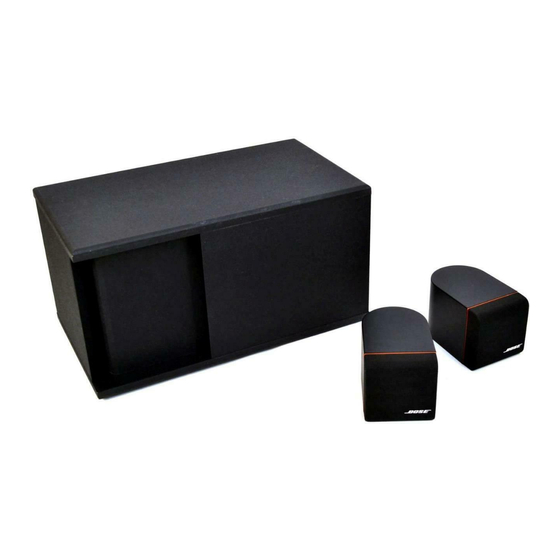
SPECIFICATIONS Dimensions Module: 7.75"H x 18.5"W x 8.5"D (20x47x22 cm) Satellite: 3"H x 3"W x 4.75"D (7.9x7.9x12.1 cm) Weight Module: 21 lbs. (9.5 kg.) Satellite: 1 lbs. (0.45 kg.) Packed System: 27 lbs. (12.3 kg.) Driver 1-5-1/4" Woofer Complement 2-2-1/4" Twiddlers™ Finish Module: Black or white, scratch-resistant, satin-finished... - Page 5 Frequency Response Curves AM-3P II bass channel frequency response with bass control at min., max. and flat positions for 30 and 200 mVrms input level. A boost occurs at 55Hz for low input levels-i.e.-30mV. The gain measurements in this graph should be referenced to the input level.
- Page 6 BLOCK DIAGRAMS Figure 3. AM-3P II Amplifier PCB Assembly Block Diagram Figure 4. AM-3P II Main PCB Assembly Block Diagram...
-
Page 7: Am-3P Ii Theory Of Operation
The AM-3P II powered Acoustimass loudspeaker system is manufactured in two variations: ® ® Home Audio and Multimedia. Both variations can be used with the Bose Lifestyle Music System or other sources that have line-level outputs. The multimedia variation was designed specifically for computer sound amplification. - Page 8 The two primary windings of the transformer are wired in series for 230V operation, and in parallel for 115V operation, depending on the position of the customer accessible voltage select switch. If the system is accidentally energized at 230V with the switch in the 115V position, the replaceable fuse (F1 located on the Main PCB assembly), will open the circuit within two minutes.
- Page 9 6. Automatic Dynamic Loudness In order to compensate for the ear’s loss of bass response at low listening levels, a BOSE ® patented (4,739,513) automatic loudness circuit is employed. This circuit automatically senses the volume level of the incoming audio signal and properly adjusts the amount of low frequency bass boost.
- Page 10 7. Low Frequency (LF) Equalization Low frequency bass channel equalization and crossover is accomplished in two active filter stages. The first stage consists of op-amp U3 (pin 5, 6, 7), capacitors C9 and C10 and resistors R19, R20, and R21. It creates the sharp band-reject attenuation below 50 Hz. The second stage consists of op-amp U5 (pin 1, 2, 3) capacitors C13 and C14, and resistors R24, R25, R26 and R27.
- Page 11 10. Power Amp (Amplifier PCB) Four identical topology class B, power amplifier stages are used to create the three power amplifier channels. One each is used for the left and right power amplifiers (2 x 20W into 4 Ohm), and two are used in bridged mode for the bass channel to create 50W into 5 Ohm. Operation of the left channel (representative) is as follows: A positive signal at op-amp input U106 pin 3 causes op-amp supply current to flow into pin 7 (and out through pin 6) through Q103.
- Page 12 12. DC Offset Protection If any one of the three amplifier channels should fail, it is likely that a large DC voltage will occur at the output of that channel. If this occurs, the DC offset detect circuit will cause the AM-3P II amplifier power supply to shut down.
-
Page 13: Am-3P Ii Disassembly/Assembly Procedures
AM-3P II DISASSEMBLY/ASSEMBLY PROCEDURES Bass Module 3. Main PCB Assembly Removal NOTE: Refer to Figures 6 and 7 (pages 29 and 30) for an exploded view of the module. Numbers in A. Remove 3 screws (6) that secure the Main parentheses reference the individual parts displayed PCB (5) to the adapter bracket (8). - Page 14 C. Push down the corners of the PCB until all 4 7. Amplifier PCB Assembly Removal adapter bracket snaps (not shown) engage. Make sure that the J5 connector pins are NOTE: It is not necessary to completely completely inserted into the mating connector disassemble the unit to access the Amplifier PCB housing.
- Page 15 C. Lower the PCB (solder side up) into place on B. Align the screw holes on the transformer with top of the transformer cup. There are holes in those on the cup. each corner of the PCB that align with the locator pins on the cup.
- Page 16 D. Secure the cup to the module with 2 screws (10). C. Remount the woofer (21) to the module using 4 screws (22). Repeat the woofer test procedures. NOTE: If no further servicing of the unit is required, refer to the simplified steps provided in Procedure 10 to reassemble the unit.
- Page 17 3. Twiddler Removal 7. Connector Removal A. Remove Grille from enclosure. Use Use Procedure 1 and 3 to access the inside of Procedure 1. the satellite enclosure. B. Remove the 4 screws (3) holding the twiddler A. After the twiddler has been removed, pull out (2) in place.
-
Page 18: Am-3P Ii Test Procedures
AM-3P II TEST PROCEDURES 1. Turn-On Test Satellite Test Procedures NOTES: Refer to the AM-3P II Main PCB NOTE: These procedures test the satellite schematic for the location of the J7 mini-jack without the bass module. input, pins 1 and 3. The On/Off Control Circuit is located on this schematic. - Page 19 3. Tone Control Test Frequency Relative Response -2.1 dB ± 1.5 dB 360 Hz NOTE: This test can be performed with a fully assembled module. 1 kHz 0 dB A. Connect an oscillator to the module’s L/R -3.5 dB ± 1.5 dB audio input terminals.
- Page 20 9. Woofer Phase Test 7. Air Leak Test A. Disconnect the woofer (connector J4) from the NOTE: Part A of this test can be performed with Amplifier PCB. Set a DC power supply to 8 a fully assembled module. volts. Connect the positive supply lead to the positive (+) woofer connection (red) and the A.
- Page 21 C. Measure the voltage across the load. It should Frequency Relative Response be approximately 15.8 volts (50 watts). The signal should look undistorted when viewed on an -18.0 dB ± 2.0 dB 20 Hz oscilloscope. +1.8 dB ± 1.5 dB 55 Hz Complete System Tests 100 Hz...
-
Page 23: Integrated Circuit Diagrams
INTEGRATED CIRCUIT DIAGRAMS Collector Base Emitter No Connection Emitter Base Collector Collector Base Emitter No Connection Emitter Base Collector Quad Transistor Array, NPN P/N 145317 (MPQ3904) Main PCB Assembly A Output B Output A -Input A +Input B -Input B+Input Dual Operational Amplifier, DIP-8 P/N 108568 (RC 4559) Main PCB Assembly... - Page 24 Comment Name No Connection Inverting Input Non-inverting Input Negative Power Supply Input I ABC Amplifier Bias Input Output Amplifier Output Positive Power Supply Input No Connection V CC = (V+)-(V-) Bipolar Operational Transconductance Amplifier P/N 119834 (CA3080) Main PCB Assembly 146234 146235 NJM78LO8A-T3...
- Page 25 Balance Input Input Output Balance Comment Name Offset Voltage Null Input 1 Inverting Input Non-inverting Input Negative Power Supply Input Offset Voltage Null Input 2 Amplifier Output Positive Power Supply Input No Connection Single JFET Input Operational Amplifier P/N 250475-001 (LF355CN) Amplifier PCB Assembly U106, U206, U301, U401...
-
Page 26: Part Lists And Exploded Views
PART LISTS AND EXPLODED VIEWS The following section contains part lists and exploded views for the AM-3P II powered speaker system. The part lists and views are broken down as follows: • Bass Module part list and exploded view. A view of the woofer is contained in a separate figure. -
Page 27: Am-3P Ii Bass Module Part List
AM-3P II Bass Module Part List (Figures 6 and 7) Item Description Part Number *See Number Note Assy Cap,Cover,White 145105-1 Cap,Cover,Black 145105-2 Screw,Machine,8-32x.5,Pan,XREC 121316-08 Cover,Black 144590-0222 Cover,White 144590-0231 Knob,Control,White 148839-1 Knob,Control,Black 148839-2 PCB Assy.,EQ,US/International 193567-1 PCB Assy.,EQ,Europe 175302-3 PCB Assy.,Multimedia, 175302-4 US/International PCB Assy.,Multimedia,Europe... -
Page 28: Am-3P Ii Satellite Part List
AM-3P II Bass Module Part List (Figures 6 and 7) Item Description Part Number Number Note Assy Woofer Assy. 5.25" 143357 Screw,Tapp,8-11x.75,pan, XRC/SQ 172672-12 Gasket,Woofer,6.5" 104794-08 Cable,Speaker 143513 AM-3P II Satellite Part List (Figure 8) Item Description Part Number Number Note Grille Assy,Satellite,Black 175177-1... - Page 29 Main PCB PCB Connector J5 Connector Panel Housing Amplifier PCB Transformer Primary Side NOTE: WIRES SHOULD NOT CROSS UNDER GASKET OR TRANSFORMER CUP AREA. Module Label Figure 6. AM-3P II Bass Module Exploded View...
- Page 30 Figure 7. Woofer Location in Module Release Snaps Figure 8. Satellite Exploded View...
-
Page 31: Am-3P Ii Packaging List
AM-3P II Packaging List Item Description Part Number Number Note Assy Polybag,14.38x9.87x2 mil 103351 Manual,Owner's, 174871 Manual,Owner's,Multimedia only 175978 Card,Warranty, Universal 149225 Envelope,Blank,White 128450 List,Warranty,Service Stations, 122706 N. America Brochure, All Products,N. America 141478 Envelope, Warranty Registration, 123001 N. America/International Adaptor,Plug Stereo,Multimedia 128404 Adaptor,120/230V Polarized,Dual... - Page 32 AM-3P II Packaging List Item Description Part Number Number Note Assy Packing,Cushion 174448 Wire,18/2 Zip Cord,White,20 ft. 140236 Wire,18/2 Zip Cord,Alp White,20 ft., 136693 Multimedia Wire,18/2 Zip Cord,Black,20 ft. 130915 Carton,RSC,AM-3P II,US/International 175004-00 Carton,RSC,AM-3P II,Ireland 175004-01 Carton,RSC,Multimedia 175938-00 Carton,RSC,Multimedia 175938-01 Carton,Alb,Satellite,AM-4 172939 Bag,Poly,7x9x2 mil,Satellite...
- Page 33 Satellites 9 10 See Items 20 and 21 Figure 9. AM-3P II Packaging Exploded View...
-
Page 34: Am-3P Ii Main Pcb Assembly Part List
AM-3P II Main PCB Assembly Part List Resistors Reference Description Part Number Reference Designator *P/N Change Rev. 1 R1,29,*36,39,41, 10.0KΩ,5%,1/8W, 124895-1035 43-46,52,59,60, 1206 107,132,207,229, Jumper Chip,1206 124896 *See Notes 3 and 4 R3,5,33,34,38,57, 100KΩ,5%,1/8W, 124895-1045 149,249 1206 R4,17,28,108,130, 330Ω,5%,1/8W, 124895-3315 208,230 1206 R6,48,56,62... - Page 35 AM-3P II Main PCB Assembly Part List Resistors (Continued) Reference Description Part Number Reference Designator 75.0KΩ,1%,1/8W, 124894-7502 1206 162Ω,1%,1/8W, 124894-1620 1206 *See Notes 3 and 4 *R101,*102,*134, 4.99KΩ,1%,1/8W, 124894-4991 *201,*202,*234 1206 *R105,*106,*205, 3.90KΩ,5%,1/8W, 124895-3925 *See Notes 1 and 2 *206 1206 R109,209 681Ω,1%,1/8W,...
- Page 36 AM-3P II Main PCB Assembly Part List Capacitors Reference Description Part Number Reference Designator C1-4,28,30,32,35, 10uF,20%,16V,105, 137126-100 36,101,102,126, 201,202,226 C6,7,9,10,13,14, .47uF,5%,50V,85, 137127-474 112,212 C8,120,121,122, .033uF,20%,50V, 124958-3331 123,124,220,221, Z5U,1206 222,223,224 C11,103,105,111, 100pF,10%,50V, 124956-1012 115,203,205,211, 1206,SL C12,29,34,104,204 47uF,20%,16V,105, 137126-470 C15,113,114,213, .12uF,5%,50V,85, 137127-124 *See Notes 1 and 2 C16,*106,*206 .0082uF,5%,50V,85,...
- Page 37 AM-3P II Main PCB Assembly Part List Transistors Reference Description Part Number Reference Designator Q1,5,7-9,11 BPLR,N,60V, 117921 200mA,TO-92 Q2-4,6,10,12 BPLR,P,60V, 119168 200mA,TO-92 Integrated Circuits Reference Description Part Number Reference Designator Transistor,Array, 145317 Quad,N,DIP-14 U2,3,5,6,101-105 Op-Amp,Dual, 108568 DIP-8,RC4559 Op-Amp,Single, 119834 DIP-8,CA3080 Connectors Reference Description...
- Page 38 AM-3P II Main EQ PCB Assembly Part List Miscellaneous Reference Description Part Number Reference Designator Fuse,1.5A,250V, 143668-1500 *See Note 5 20x5mm *S1A,*S1B Cable Assy., 145314 *See Note 5 *P/N until 1/13/95 Quick Disc *See Note 5 *S1A,*S1B Switch,Rocker, 176259 *P/N as of 1/13/95 SPST,Wired *See Note 5 Switch,Slide,DPDT...
-
Page 39: Am-3P Ii Amplifier Pcb Assembly Part List
AM-3P II Amplifier PCB Assembly Part List Resistors Reference Description Part Number Reference Designator R30,31 5.1Ω,5%,1/4W, 121243-1215R15 52mm,CF R32,33,131,142, 10.0KΩ,5%,1/8W, 124895-1035 231,242,303,313, 1206 403,413 R34,138,238,308 1.00KΩ,5%,1/8W, 124895-1025 1206 R130,141,230,241, 100KΩ,5%,1/8W, 124895-1045 302,312,318,402, 1206 412,418 51Ω,5%,1/4W, 130102-510 *See Note Fusing *R132,*143,*232, *243,*304,*314, *404,*414 5.1 Ω,5%,1/4W,... - Page 40 AM-3P II Amplifier PCB Assembly Part List Capacitors Reference Description Part Number Reference Designator C17,125,225 10uF,20%,16V,105, 137126-100 C18,120-123,126, .0047uF,5%,50V, 131754-472 220-223, 226, X7R,1206 301-304,401-404 *C20,*24 560uF,20%, 128548 *See Note 16V,105,EL *C21,*25 10KuF,20%,35V, 143623 *See Note 105,EL C22,23,26,27,124, .033uF,20%,50V, 124958-3331 224,305,405 Z5U,1206 Diodes Reference...
- Page 41 AM-3P II Amplifier PCB Assembly Part List Integrated Circuits Reference Description Part Number Reference Designator Voltage Regulator, 146234 8V,POS,TO-92 Voltage Regulator, 146235 8V,NEG,TO-92 U106,206,301,401 Op-Amp Single, 132604 or 250475-001 DIP-8,LF355CN Connectors Reference Description Part Number Reference Designator Connector, Header 133220-05 Inline,PCB MNT,5P Connector,Header, 145305-15...
-
Page 42: Schematics And Pcb Layouts
SCHEMATICS AND PCB LAYOUTS The layout and schematic foldouts included with this manual can be used for Revisions 0 through 2 PC boards. The Main PCB had a slight etch change from revision 0 to 1, and a reversed insertion of diode D19, from revision 1 to 2. - Page 43 SPECIFICATIONS AND FEATURES SUBJECT TO CHANGE WITHOUT NOTICE 1/95: REV. 0 Bose Corporation The Mountain Framingham, Massachusetts USA 01701 P/N 175032 FOR TECHNICAL ASSISTANCE OR PART ORDERS, CALL 800-367-4008...