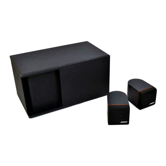
Bose ACOUSTIMASS 3 Service Manual
Powered speaker system
Hide thumbs
Also See for ACOUSTIMASS 3:
- Owner's manual (17 pages) ,
- Owner's manual (10 pages) ,
- Manual (43 pages)
Advertisement
Advertisement

Related Manuals for Bose ACOUSTIMASS 3


Summary of Contents for Bose ACOUSTIMASS 3
- Page 1 ® ACOUSTIMASS -3 POWERED SPEAKER SYSTEM Service Manual © 1992 Bose Corporation...
-
Page 2: Table Of Contents
® BOSE CORPORATION WHICH IS BEING FURNISHED ONLY FOR THE PURPOSE OF SERVICING THE IDENTIFIED BOSE PRODUCT BY AN AUTHORIZED BOSE SERVICE CENTER OR OWNER OF THE BOSE PRODUCT, AND SHALL NOT BE REPRODUCED OR USED FOR ANY OTHER PURPOSE. -
Page 3: Safety Information
SAFETY INFORMATION 1. Parts that have special safety characteristics are identified by the symbol on schematics or by special notes on the parts list. Use only replacement parts that have critical characteristics recommended by the manufacturer. 2. Make leakage current or resistance measurements to determine that exposed parts are acceptably insulated from the supply circuit before returning the unit to the customer. -
Page 4: Specifications
SPECIFICATIONS Dimensions Module: 7.75"H x 18.5"W x 8.5"D (20x47x22 cm) Satellite: 4.5"H x 4.5"W x 3.5" D (11x11x9 cm) Weight Module: 21 lbs. (9.5 kg.) Satellite: 1.3 lbs. (0.6 kg.) Packed System: 27 lbs. (12.3 kg.) Driver 1-5-1/4" Woofer Complement 2-2-1/4"... - Page 5 Frequency Response Curves Figure 1. Bass Channel Frequency Response Curve Figure 2. Left/Right Channel Frequency Response Curve...
-
Page 6: Block Diagrams
BLOCK DIAGRAM Figure 3. AM-3P Amplifier PCB Assembly Block Diagram Figure 4. AM-3P Equalizer PCB Assembly Block Diagram... -
Page 7: Theory Of Operation
GENERAL The AM-3P powered Acoustimass loudspeaker system is designed to be used with the BOSE Lifestyle Music Center (or other line level audio source) to form a simple, yet complete, home audio system. - Page 8 A non-serviceable thermal fuse is located inside the transformer to limit the maximum temperature to 145 °C under abnormal conditions. However, in most cases the external fuse (F1) should fail before the internal transformer thermal fuse. The thermal fuse can be checked by measuring the continuity between pins 1 and 4 (black and white wire) of the primary connector.
- Page 9 6. Automatic Dynamic Loudness In order to compensate for the ear’s loss of bass response at low listening levels, a BOSE patented (4,739,513) automatic loudness circuit is employed. This circuit automatically senses the volume level of the incoming audio signal and properly adjusts the amount of low frequency bass boost.
- Page 10 8. Auto Turn-On/Off Mute An improved version of auto turn-on/off is used in the AM-3P. A separate 3.5 mm stereo mini- jack (J7) is used to receive the turn-on signal from the serial data output of the Lifestyle music center. When the 3.5 mm plug is inserted, the audio sense circuit is disabled and the amplifier outputs will only unmute if the DC control signal is present at J7 pin 3.
- Page 11 10. Power Amp (Amplifier PCB) Four identical topology class B, power amplifier stages are used to create the three power amplifier channels. One each is used for the left and right power amplifiers (2 x 20W into 4 Ohm), and two are used in bridged mode for the bass channel to create 50W into 5 Ohm. Operation of the left channel (representative) is as follows: A positive signal at op-amp input U106 pin 3 causes op-amp supply current to flow into pin 7 (and out through pin 6) through Q103.
- Page 12 12. DC Offset Protection If any one of the three amplifier channels should fail, it is likely that a large DC voltage will occur at the output of that channel. If this occurs, the DC offset detect circuit will cause the AM-3P amplifier power supply to shut down.
- Page 13 NOTES FOR FUTURE REFERENCE...
-
Page 14: Disassembly/Assembly Procedures
AM-3P DISASSEMBLY/ ASSEMBLY PROCEDURES Module Procedures 1.Cover Removal 3. EQ PCB Assembly Removal NOTE: Refer to Figures 5 and 6 for an exploded A. Remove 1 screw (6) which secures the PCB view of the module. Certain parts will be referred (5) to the adapter bracket (8). - Page 15 C. Push down the corners of the PCB until all 4 D. Secure the heatsink and adapter bracket to adapter bracket snaps (not shown) engage. the module with 6 screws (10). Make sure that the J5 connector pins are completely re-connected to the mating connector 7.
- Page 16 C. Lower the PCB (solder side up) into place on B. Align the screw holes on the transformer with top of the transformer cup. There are holes in those on the cup. each corner of the PCB that align with the locater pins on the cup.The transistors (on PCB edges) C.
- Page 17 D. Secure the cup to the module with 2 screws (10). C. Re-mount the woofer (21) to the module using 4 screws (22). Repeat the woofer test procedures. NOTE: If no further servicing of the unit is required,refer to the simplified steps provided in Procedure 10 to re-assemble the unit.
- Page 18 3. Twiddler Removal 5. Terminal Cover Removal A. Remove the 4 screws (4) holding the twiddler NOTE: There are catches on the top and bottom (3) in place. Lift the twiddler out and cut the wires (inside) of the terminal cover (7) that hook it into connected to the twiddler as close to its terminals the satellite enclosure.
- Page 19 NOTES FOR FUTURE REFERENCE...
-
Page 20: Test Procedures
AM-3P TEST PROCEDURES 1. Turn-On Test Satellite Test Procedures NOTES: Refer to the AM-3P EQ PCB schematic NOTE: Use these procedures only when for the location of the J7 mini-jack input,pins 1 satellites come in to be serviced (without the and 3. - Page 21 Frequency Relative Response 3. Tone Control Test 1 kHz 0 dB NOTE: This test can be performed with a fully -5.2 dB ± 1.5 dB 2 kHz assembled module. +1.0 dB ± 1.5 dB 10 kHz A. Connect an oscillator to the module’s L/R audio input terminals.
- Page 22 9. Woofer Phase Test 7. Air Leak Test A. Disconnect the woofer (connector J4) from the NOTE: Part A. of this test can be performed with Amplifier PCB. Set a DC power supply to 8 a fully assembled module. volts. Connect the positive supply lead to the positive (+) woofer connection (red) and the A.
- Page 23 Frequency Relative Response -18.0 dB ± 2.0 dB 20 Hz C. Measure the voltage across the load. It should be approximately 15.8 volts (50 watts). The signal should look undistorted when viewed on an +1.8 dB ± 1.5 dB 55 Hz oscilloscope.
-
Page 24: Parts Lists And Exploded Views
PARTS LISTS AND EXPLODED VIEWS The following section contains parts lists and exploded views for the AM-3P powered speaker system. The parts lists are broken down as follows: - Module Parts List and Module Exploded View. A view of the woofer is contained in a separate figure. - Page 25 AM-3P Bass Module Parts List (Figures 5 and 6) Item Description Part Number Qty. See Note Number Module Cap-Cover,White 145105-1 Cap-Cover,Black 145105-2 Screw-Mach., 121316-08 8-32x1/2,PAN,XREC Cover-White,International 144590-0231 Cover-Black,International 144590-0222 Cover-Black,Japan 144590-0822 Knob-Control,White 148839-1 Knob-Control,Black 148839-2 PCB Assy-EQ,US/International 193567-1 PCB Assy-EQ,Japan 143624-2 PCB Assy-EQ,Europe 143624-3 replaced by 175302-3 1 Screw-...
- Page 26 AM-3P Module Parts List (Continued) Item Description Part Number Qty. See Note Number Module Transformer -120/240V ( 143051 US/Eur.) Transformer -100V (Japan) 145318 Cup-Transformer,Black 144589-2 Gasket-Transformer Cup 143514 Woofer -5-1/4" 143357 Screw- 137527-12 HIRS,8-10x3/4,PAN,XRC/SQ Woofer Gasket 104794-08 Cable- 143513 Speaker,Safety Controlled AM-3P Satellite Parts List (Figure 7) Item Description...
- Page 27 FIGURE 6 Figure 5. AM-3P Bass Module Exploded View...
- Page 28 VIEW A Figure 6. Woofer Location in Module Figure 7. AM-3P Satellite Exploded View...
- Page 29 AM-3P Packaging Parts List (Figure 8) Item Description Part Number Qty. See Note Number Carton Polybag (Satellite Parts) 144677 Packing-Insert,EPS 136436 Literature Kit (N.America) 143516-1 Literature Kit (Europe) 143516-2 Literature Kit (UK) 143516-4 Literature Kit (Australia) 143516-5 Literature Kit (International) 143516-6 which consists of: Polybag...
- Page 30 AM-3P Packaging Parts List (Continued) Item Description Part Number Qty. See Note Number Carton Line Cord-120V,Detachable 146999 (N.America,International) Line Cord-Euro,Detachable 148203 (Europe) Line Cord-100V,Detachable 145316 (Japan) Line Cord-230V UK,Detachable 134725 (UK) Line Cord-230V Aus., 134726 Detachable (Australia) Carton-Generic 149086 Carton-Japan 145757 Figure 8.
- Page 31 AM-3P EQ PCB Assembly Parts List Resistors Description Part Number See Note Reference Designator R1,4,29,39,41,43- 10kΩ,5%,1/8W, 124895-1035 45,46,52,59,60, Chip 107,120,132,207, 220,229,232 R2,3,5,33,34,38, 100kΩ,5%,1/8W, 124895-1045 57,149,249 Chip R6,48,56,62 1MΩ,5%,1/8W, 124895-1055 Chip R7,8,36,42,47, 20kΩ,5%,1/8W, 124895-2035 55,58,68,129 Chip R9,37,49,66,67 2kΩ,5%,1/8W, 124895-2025 Chip 27.4kΩ,1%,1/8W, 124894-2742 Chip R11,15,32...
- Page 32 Resistors (Continued) Reference Description Part Number See Note Designator 162Ω,1%,1/8W, 124894-1620 Chip R105,106,205,206 3.9kΩ,5%,1/8W, 124895-3925 Chip R109,209 681Ω,1%,1/8W, 124894-6810 Chip R110,210 6.19kΩ,1%,1/8W, 124894-6191 Chip R111,127,128, 12.1kΩ,1%,1/8W, 124894-1212 211,227,228 Chip R116,216 20kΩ,1%,1/8W, 124894-2002 Chip R117,217 6.81kΩ,1%,1/8W, 124894-6811 Chip R118,218 30.1kΩ,1%,1/8W, 124894-3012 Chip R122,124,222,224 100kΩ,1%,1/8W, 124894-1003...
- Page 33 Capacitors Reference Description Part Number See Note Designator C1-4,28,30,32,35, 10µF,20%,EL 137126-100 36,101,102,126, 201,202,226 C6,7,9,10,13,14 .47µF,5%,Box 137127-474 Film C8,120-124, 33000pF,20%, 124958-3331 220-224 Chip C11,103,105,111, 100pF,5%,Chip 124956-1012 115,203,205,211, C12,29,34,104, 47µF,20%,EL 137126-470 C15,113,114,213, .12µF,5%,Box 137127-124 Film C16,106,109,110, .0082µF,5%,Film 137123-822 206,209,210 33µF,20%,EL, 147522-330 Bi-polar C31,116,117,216, .1µF,5%,Film 137123-104...
- Page 34 Connectors Reference Description Part Number See Note Designator None AC Power 146563 Connector Connector- 145315-5 Header,5 pin, Hi Current Connector-Dual 145310 Stereo,Mini Connector-Quad 145309 Phono Connector-Quad 145308 Speaker Terminal AC Jack 145306 Connector Potentiometers Reference Description Part Number See Note Designator Dual 10K-Volume 145311...
- Page 35 Miscellaneous Reference Description Part Number See Note Designator W1-15 Chip Jumper 124896 NOTES 1. This part is used on the -1 and -2 PCBs only. 2. This part is used on the -3 PCB only. 3. This part is used on the -1 and -3 PCBs only. 4.
- Page 36 AM-3P Amplifier PCB Assembly Parts List Resistors Reference Description Part Number See Note Designator R30,31 5.1Ω,5%,1/4W, 121243-1215R15 52 mm,Carbon Film R32,33,131,142, 10kΩ,5%,1/8W, 124895-1035 231,242,303,313, Chip 403,413 R34,138,238,308 1kΩ,5%,1/8W, 124895-1025 Chip R130,141,230, 100kΩ,5%,1/8W, 124895-1045 241,302,312,318, Chip 402,412,418 51Ω,5%,1/4W, 130102-510 Fusing R132,143,232, 243,304,314,404, 5.1Ω,5%,1/4W, 130102-5R1...
- Page 37 Capacitors Reference Description Part Number See Note Designator C17,125,225 10µF,20%,EL 137126-100 C18,120-123,126, .0047µF,5%,Chip 131754-472 220-223,226, 301-304,401-404 C20,24 560µF,20%,EL 128548 C21,25 10000µF,35V, 143623 105C,EL C22,23,26,27,124, 33000pF,20%, 124958-3331 224,305,405 Chip Transistors Reference Description Part Number See Note Designator Q1,102,103,110, NPN,Tape 117921 202,203,210,302, 303,310,402,403, Q101,104,109, PNP,Small...
- Page 38 Connectors and Jumpers Reference Description Part Number See Note Designator Connector- 133220-05 Header,5 pole, Med.Current Connector- 145305-15 Header,Rt.Angle, 15 pin Connector- 133220-02 Header,2 pole, Med.Current,.156 W1,4,12,34,35,47 Jumper-Chip,0805 133627 W2,3,5-11,14-27, Jumper-Chip 124896 29-33,36-42,45, 46,48,49 W1,3-46 Jumper-Chip 124896 Relays and Rectifiers Reference Description Part Number See Note...
- Page 39 NOTES FOR FUTURE REFERENCE...
-
Page 40: Schematics And Pcb Layouts
SCHEMATICS AND PCB LAYOUTS Two schematics are enclosed backed by their respective PCB layouts. The following PCB assemblies are contained here: EQ PCB schematic backed by component side and solder side PCB layouts Amplifier PCB schematic backed by component side and solder side PCB layouts... - Page 41 NOTES FOR FUTURE REFERENCE...
- Page 42 SPECIFICATIONS AND FEATURES SUBJECT TO CHANGE WITHOUT NOTICE 12/92: REV.0 Bose Corporation The Mountain Framingham, Massachusetts USA 01701 P/N 149821 FOR TECHNICAL ASSISTANCE OR PARTS ORDERING,CALL 800-367-4008...