Table of Contents
Advertisement
Quick Links
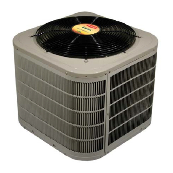
MODEL 223R
LEGACYT SERIES R- -22 HEAT PUMP
SIZES 018 TO 060
1- -1/2 TO 5 NOMINAL TONS
Fig. 1 --- 223R
NOTE: Read the entire instruction manual before starting the
installation.
Installation Instructions
TM
A05236
TABLE OF CONTENTS
. . . . . . . . . . . . . . . . . . . . . . . . . . . . . .
Step 2 - - Install on Solid Pad
. . . . . . . . . . . . . . . . . . . . . . . . .
. . . . . . . . . . . . . . . . . . . . . . . . . . .
. . . . . . . . . . . . . . . . . . . . . . . . . .
PAGE
. . . . . . . . . . . . . . . . . . . . . . .
. . . . . . . . . . . . .
3 - - 10
. . . . . . . . . . . . . . .
. . . . . . . . . . . . . . . . . . . . . .
. . . . . . . . . . . . . . . . . .
. . . . . . . . . . . . . . . . . . . . . .
3 - - 4
. . . . . . . . . . . . . . . . .
. . . . . . . . . . . . . .
4 - - 6
. . . . . . . . . . . .
6 - - 7
. . . . . . . . . . . . .
. . . . . . . . . . . . . .
7 - - 9
. . . . . . . . . . . . . . . . . . . . . . . . .
. . . . . . . . . . . . . . . . . . . . . .
2
2
3
3
3
3
4
7
7
10
10
10
Advertisement
Table of Contents

Related Manuals for Bryant LEGACY 223R


Summary of Contents for Bryant LEGACY 223R
-
Page 1: Table Of Contents
MODEL 223R LEGACYT SERIES R- -22 HEAT PUMP SIZES 018 TO 060 1- -1/2 TO 5 NOMINAL TONS Installation Instructions TABLE OF CONTENTS PAGE SAFETY CONSIDERATIONS ..... . . INSTALLATION RECOMMENDATIONS . -
Page 2: Safety Considerations
SAFETY CONSIDERATIONS INSTALLATION RECOMMENDATIONS Improper installation, adjustment, alteration, service, NOTE: In some cases noise in the living area has been traced to maintenance, or use can cause explosion, fire, electrical shock, or gas pulsations from improper installation of equipment. other conditions which may cause death, personal injury, or 1. -
Page 3: Installation
INSTALLATION On rooftop applications, locate unit at least 6 in. above roof surface. STEP 1 —Check Equipment and Job Site STEP 4 —Operating Ambient Unpack Unit The minimum outdoor operating ambient in cooling mode is Move to final location. Remove carton taking care not to damage 55°F, and the maximum outdoor operating ambient in cooling unit. -
Page 4: Step 6 -Check Defrost Thermostat
STEP 6 —Check Defrost Thermostat 10 O'CLOCK 2 O'CLOCK Check defrost thermostat to ensure it is properly located and securely attached. There is a liquid header with a brass distributor SENSING BULB and feeder tube going into outdoor coil. At the end of the one of the feeder tubes, there is a 3/8 in. - Page 5 Outdoor units may be connected to indoor section using Remove plastic retainer holding outdoor piston in liquid service accessory tubing package or field- -supplied refrigerant grade valve, leaving the piston and piston retainer inside the valve. tubing of correct size and condition. For tubing requirements Connect sweat/flare adapter provided, to valve.
-
Page 6: Step 8 -Make Electrical Connections
STEP 8 —Make Electrical Connections IMPORTANT: Check to be certain factory tubing on both indoor and outdoor unit has not shifted during shipment. Ensure WARNING tubes are not rubbing against each other or any sheet metal. Pay close attention to feeder tubes, makings sure wire ties on feeder tubes are secure and tight. -
Page 7: Step 9 -Compressor Crankcase Heater
STEP 11 —Start- -Up Connect Control Wiring Route 24v control wires through control wiring grommet and CAUTION connect leads to control wiring. See Thermostat Installation Instructions for wiring specific unit combinations. (See Fig. 9.) Use No. 18 AWG color- -coded, insulated (35°C minimum) wire. PERSONAL INJURY HAZARD If thermostat is located more than 100 ft from unit, as measured Failure to follow this caution may result in personal... - Page 8 HEAT TYPICAL HP THERMOSTAT FAN COIL PUMP 24 VAC HOT 24 VAC COM HEAT STAGE 2 COOL/HEAT STAGE 1 INDOOR FAN RVS COOLING EMERGENCY IF AVAILABLE HEAT LEGEND 24-V FACTORY WIRING 24-V FIELD WIRING FIELD SPLICE CONNECTION OUTDOOR THERMOSTAT EMERGENCY HEAT RELAY SUPPLEMENTAL HEAT RELAY A02325 / A97413 Fig.
- Page 9 Sequence of Operation Quiet Shift Quiet shift is a field selectable defrost mode (factory set to OFF), NOTE: Defrost control board is equipped with 5 minute lockout which will eliminate occasional noise that could be heard at the timer that is initiated upon any interruption of power. start of defrost cycle and restarting of heating cycle.
-
Page 10: Step 12 -Check Charge
STEP 12 —Check Charge 4. Leave Owner’s Manual with owner. Explain system operation and periodic maintenance requirements outlined Factory charge and charging method are shown on unit rating in manual. plate. To check charge in cooling mode, refer to Cooling Only 5.