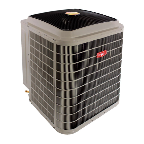
Bryant EVOLUTION EXTREME 280ANV Installation Instructions Manual
Variable speed heat pump with puron refrigerant (2-5 ton)
Hide thumbs
Also See for EVOLUTION EXTREME 280ANV:
- Owner's manual (4 pages) ,
- Owner's manual (4 pages)
Table of Contents
Advertisement
280ANV EVOLUTION
VARIABLE SPEED HEAT PUMP
WITH PURONr REFRIGERANT
(2 - - 5 Ton)
NOTE: Read the entire instruction manual before starting the installation.
. . . . . . . . . . . . . . . . . . . . . . . . . . . . . . . . . . . . . . . . . . . . . . . . . . . . . . . . . . . . . . . . . . . . . . . . . . .
. . . . . . . . . . . . . . . . . . . . . . . . . . . . . . . . . . . . . . . . . . . . . . . . . . . . . . . . . . . . . . . . . . . . . . . . . .
. . . . . . . . . . . . . . . . . . . . . . . . . . . . . . . . . . . . . . . . . . . . . . . . . . . . . . . . . . . . . . . . . . . . . . . . . .
. . . . . . . . . . . . . . . . . . . . . . . . . . . . . . . . . . . . . . . . . . . . . . . . . . . . . . . . . . . . . . . . . . . . . . . . . . . . . . . . .
R
EXTREME
Installation Instructions
TABLE OF CONTENTS
. . . . . . . . . . . . . . . . . . . . . . . . . . . . . . . . . . . . . . . . . . . . . . . . . . . . . . . . . . . . . . . . . . .
. . . . . . . . . . . . . . . . . . . . . . . . . . . . . . . . . . . . . . . . . . . . . . . . . . . . . . . .
. . . . . . . . . . . . . . . . . . . . . . . . . . . . . . . . . . . . . . . . . . . . . . . . . . . . . . . . . . .
. . . . . . . . . . . . . . . . . . . . . . . . . . . . . . . . . . . . . . . . . . . . . . . . . . . . . . . . . . . . . . . . . . .
. . . . . . . . . . . . . . . . . . . . . . . . . . . . . . . . . . . . . . . . . . . . . . . . . . . . . . . . . . . . . . .
. . . . . . . . . . . . . . . . . . . . . . . . . . . . . . . . . . . . . . . . . . . . . . . . . . . . . . . . . . . . . . . . . . .
. . . . . . . . . . . . . . . . . . . . . . . . . . . . . . . . . . . . . . . . . . . . . . . . . . . . . . . . . . . . . . . . . . . . . . . .
. . . . . . . . . . . . . . . . . . . . . . . . . . . . . . . . . . . . . . . . . . . . . . . . . . . . . . .
. . . . . . . . . . . . . . . . . . . . . . . . . . . . . . . . . . . . . . . . . . . . . . . . . . . . . . . . . .
. . . . . . . . . . . . . . . . . . . . . . . . . . . . . . . . . . . . . . . . . . . . . . . . . . . . . . . . . . .
. . . . . . . . . . . . . . . . . . . . . . . . . . . . . . . . . . . . . . . . . . . . . . . . . . . . . . . . . .
. . . . . . . . . . . . . . . . . . . . . . . . . . . . . . . . . . . . . . . . . . . . . . . . . . . . . . . . . . . . . . . . . . .
. . . . . . . . . . . . . . . . . . . . . . . . . . . . . . . . . . . . . . . . . . . . . . . . . . . . . . . . . . . . . . . . . . . . . . . . . .
. . . . . . . . . . . . . . . . . . . . . . . . . . . . . . . . . . . . . . . . . . . . . . . . . . . . . . . . . . . . . . . . . . .
. . . . . . . . . . . . . . . . . . . . . . . . . . . . . . . . . . . . . . . . . . . . . . . . . . . . . . . . . . . .
. . . . . . . . . . . . . . . . . . . . . . . . . . . . . . . . . . . . . . . . . . . . . . . . . . . . . . . . . . . . . . . . . . . . . .
. . . . . . . . . . . . . . . . . . . . . . . . . . . . . . . . . . . . . . . . . . .
. . . . . . . . . . . . . . . . . . . . . . . . . . . . . . . . . . . . . . . . . . . . . .
PAGE NO.
2
3
3- -11
4
4
4
4
4
4
5- -6
7
7
8
8
8- -10
10- -11
11
12
12- -17
18
18
18
Advertisement
Table of Contents

Related Manuals for Bryant EVOLUTION EXTREME 280ANV


Summary of Contents for Bryant EVOLUTION EXTREME 280ANV
-
Page 1: Table Of Contents
280ANV EVOLUTION EXTREME VARIABLE SPEED HEAT PUMP WITH PURONr REFRIGERANT (2 - - 5 Ton) Installation Instructions NOTE: Read the entire instruction manual before starting the installation. TABLE OF CONTENTS PAGE NO. SAFETY CONSIDERATIONS ..............INSTALLATION RECOMMENDATIONS . -
Page 2: Safety Considerations
Information in these installation instructions pertains only to Indoor Thermostat Control Options 280ANV series units. Evolution Model Control SAFETY CONSIDERATIONS Improper installation, adjustment, alteration, service, maintenance, 280ANV Yes* or use can cause explosion, fire, electrical shock, or other conditions which may cause death, personal injury, or property * Requires model SYSTXBBUID01 ---D or SYSTXBBUIZ01 ---D software damage. -
Page 3: Installation Recommendations
Installation Recommendations Adjust refrigerant charge by adding or removing the charge to/from the unit depending on lineset length and indoor unit as In some cases noise in the living area has been traced to gas calculated and displayed on the UI. The user interface (UI) pulsations from improper installation of equipment. -
Page 4: Step 2 - Install On Solid Pad
Step 2 — Install on a Solid, Level Mounting Pad CAUTION If conditions or local codes require the unit be attached to pad, tie down bolts should be used and fastened through knockouts UNIT OPERATION HAZARD provided in unit base pan. Refer to unit mounting pattern in Fig. 3 Failure to follow this caution may result in equipment to determine base pan size and knockout hole location. -
Page 5: Step 7 - Making Piping Connections
Step 7 — Make Piping Connections CAUTION WARNING UNIT DAMAGE HAZARD PERSONAL INJURY AND UNIT DAMAGE Failure to follow this caution may result in equipment HAZARD damage or improper operation. Failure to follow this warning could result in personal injury or If ANY refrigerant tubing is buried, provide a 6 in. - Page 6 Outdoor Unit Connected to Factory- - Approved Indoor Unit Outdoor unit contains correct system refrigerant charge for operation with factory- -approved, AHRI- -rated smallest indoor unit when connected by 15 ft. (4.57 m) of field- -supplied or factory- -accessory tubing, and factory- -supplied filter drier. Check refrigerant charge for maximum efficiency.
-
Page 7: Step 8 - Make Electrical Connections
Connect Ground and Power Wires 5000 Connect ground wire to ground connection in control box for 4500 safety. Connect power wiring to contactor as shown in Fig. 8. 4000 LEAK IN 3500 DISCONNECT SYSTEM PER N. E. C. AND/OR 3000 LOCAL CODES 2500 CONTACTOR... -
Page 8: Step 10 - Install Accessories
External to the unit, the same accessories such as the liquid line solenoid, support feet, snow rack, wind baffle etc., are available on other Bryant units can also be used on this line of product. Refer to the individual Installation Instructions packaged with kits or accessories when installing. -
Page 9: General Information
Crankcase Heater Operation Utility Interface With Evolution Control This unit has an internal crankcase heater that will be energized The utility curtailment relay should be wired between the two during the off cycle and is intelligently demanded by the system to UTIL connections on the control board for this Evolution prevent the compressor from being the coldest part of the system Communicating System (see Fig. -
Page 10: Step 13 - Check Charge
The control board accumulates compressor run time. As the subcooling method. Compare the subcooling taken at the liquid accumulated run time approaches the selected defrost interval time, service valve to the subcooling target (LiqLin SC TGT) listed on the control board monitors the coil temperature sensor for a defrost the charging screen. -
Page 11: Step 14 - Pumpdown & Evacuation
Charging In Cooling Mode - 280ANV024/036 Charging In Cooling Mode - 280ANV048/060 See user interface set in Charging Mode See user interface set in Charging Mode Heating Check Chart - 280ANV024/036 Heating Check Chart - 280ANV048/060 For use in Heating Charging Mode only For use in Heating Charging Mode only 2757 3102... -
Page 12: Major Components
MAJOR COMPONENTS Compressor Brush- -less Permanent Magnet Motor (BPM): S The motor inductance reacts to the drive current and a sinusoidal Variable speed Control Board current is induced through the motor windings. The HP control board controls the following functions: S The sinusoidal current sets a rotating magnetic field, at the S Compressor speed frequency set by the drive. - Page 13 Pressure Switch Protection THERMISTOR CURVE The outdoor unit is equipped with high pressure switch. If the control senses the opening of a high pressure switch, it will respond as follows: 1. De- -energize the contactor. 2. Keep the outdoor fan operating for 15 minutes. 3.
- Page 14 Outdoor Coil Thermistor Suction Thermistor (OST) The outdoor coil thermistor is a 10Kohm resistor used for multiple Suction Thermistor is used for assisting in EXV control and must system operations. It provides the coil/liquid line temperature to be secured on the suction tube and aligned longitudinally to the the heat pump board and user interface.
- Page 15 Status Codes EXAMPLE: 3 short flashes followed by 2 long flashes indicates a 32 code. Table 7 shows the status codes flashed by the amber status light. Table 7 shows this to be low pressure switch open. Most system problems can be diagnosed by reading the status code as flashed by the amber status light on the control board.
- Page 16 SEC2 SEC1 PWM2 PWM1 PL11 COMM STATUS LS Y UTIL FORCED A B C NO MODEL DEFROST Utility Interface* A11544 Fig. 20 - - Variable Speed Control Board with optional Utility Relay SEC2 SEC1 PWM2 PWM1 PL11 COMM STATUS LS Y UTIL FORCED A B C NO...
- Page 17 Table 7 – Troubleshooting FLASH CODE RESET TIME FAULT DESCRIPTION SENT TO UI (AMBER LED) (minutes) --- --- Standby ON, no flash Variable Capacity or Emergency --- --- 1, pause Mode 1 (2 sec ON), longer pause --- --- Variable Speed Range Cutback second OFF) Communications Loss Invalid Model...
-
Page 18: Final Checks
FINAL CHECKS CARE AND MAINTENANCE IMPORTANT: IMPORTANT: Before leaving job, be For continuing high performance and to minimize possible equipment failure, periodic maintenance must be sure to do the following: performed on this equipment. 1. Ensure that all wiring is routed away from tubing Frequency of maintenance may vary depending upon and sheet metal edges to prevent rub- -through or geographic areas, such as coastal applications.