Table of Contents
Advertisement
Quick Links
Advertisement
Table of Contents

Related Manuals for Fluke ScopeMeter 124B


Summary of Contents for Fluke ScopeMeter 124B
- Page 1 123B/124B/125B ® Industrial ScopeMeter Users Manual January 2016 © 2016 Fluke Corporation. All rights reserved. Specifications are subject to change without notice. All product names are trademarks of their respective companies. Fluke-Direct .com sales@GlobalTestSupply.com 1.888.610.7664...
- Page 2 LIMITED WARRANTY AND LIMITATION OF LIABILITY Each Fluke product is warranted to be free from defects in material and workmanship under normal use and service. The warranty period is three years and begins on the date of shipment. Parts, product repairs, and services are warranted for 90 days. This warranty extends only to the original buyer or end-user customer of a Fluke authorized reseller, and does not apply to fuses, disposable batteries, or to any product which, in Fluke's opinion, has been misused, altered, neglected, contaminated, or damaged by accident or abnormal conditions of operation or handling.
-
Page 3: Table Of Contents
Table of Contents Title Page Introduction ........................1 How to Contact Fluke ..................... 1 Safety Information ......................1 Test Tool Kit Contents ....................5 Get Started ........................7 Battery Pack ......................7 Mains Power Source ....................8 SD Memory Cards ..................... 8 Test Tool Setup ...................... - Page 4 Time Base ......................23 Waveform Position ....................23 Noise Reduction ....................24 Glitch Display ....................... 24 Waveform Smoothing ................... 25 Reading Smoothing ....................26 How to Display the Envelope of a Waveform ............26 Waveform Acquisition ....................27 Fluke-Direct .com sales@GlobalTestSupply.com 1.888.610.7664...
- Page 5 Start and Stop Meter Recording ................50 Cursor Measurements ....................52 Zoom In/Out on Logged Meter Data ................53 Events ........................53 Scope Record Mode ....................53 Save and Recall Data Sets .................... 55 Test Sequence ......................56 Setting Recall ......................57 Fluke-Direct .com sales@GlobalTestSupply.com 1.888.610.7664...
- Page 6 Specifications ........................ 69 Dual Input Oscilloscope .................... 69 Dual Input Meter ....................... 71 Cursor Readout (124B, 125B)................... 78 Recorder ........................79 Power Quality (125B) ....................80 Field Bus Measurements (125B) ................81 Miscellaneous ......................82 Environmental ......................83 Fluke-Direct .com sales@GlobalTestSupply.com 1.888.610.7664...
- Page 7 Harmonics Power Measurements ..................41 Bus Measurement Inputs....................... 43 Field Bus Test Screen ......................44 Test Signal Properties ......................45 Bus Test Screen Indicators ....................46 Replaceable Parts and Accessories ..................65 Optional Accessories ......................66 Fluke-Direct .com sales@GlobalTestSupply.com 1.888.610.7664...
- Page 8 Bus Health Indicator Boundaries ................... 47 WiFi USB Adapter ......................... 59 10:1 Scope Probes ........................ 63 Max. Input Voltage vs. Frequency for BB120 and STL120-IV ..........85 Safe Handling: Max. Voltage Between Test Tool Reference and Earth Ground ....85 Fluke-Direct .com sales@GlobalTestSupply.com 1.888.610.7664...
-
Page 9: Introduction
To prevent possible electrical shock, fire, or personal injury: • Read all safety information before you use the Product. • Use the Product only as specified, or the protection supplied by the Product can be compromised. • Carefully read all instructions. Fluke-Direct .com sales@GlobalTestSupply.com 1.888.610.7664... - Page 10 • Do not use the Product around explosive • Do not apply more than the rated gas, vapor, or in damp or wet voltage, between the terminals or environments. between each terminal and earth ground. Fluke-Direct .com sales@GlobalTestSupply.com 1.888.610.7664...
- Page 11 Remove all probes, test leads, and approved eye protection and approved accessories before the battery door is personal-protective equipment where opened. necessary. • Remove all probes, test leads, and accessories that are not necessary for the measurement. Fluke-Direct .com sales@GlobalTestSupply.com 1.888.610.7664...
- Page 12 This product contains a Lithium-ion battery. Do not mix with solid waste stream. Spent batteries should be disposed of by a qualified recycler or hazardous materials handler per local regulations. Contact your authorized Fluke Service Center for recycling information. This product complies with the WEEE Directive marking requirements. The affixed label indicates that you must not discard this electrical/electronic product in domestic household waste.
-
Page 13: Test Tool Kit Contents
Table 2 is a list of the items included in your Test Tool kit. Also see Figure 1. Table 2. Packing List Item Description 12x-B 12x-B/S Fluke Test Tool 123B, 124B or 125B 123B/S, 124B/S or 125B/S • • Rechargeable Li-ion Battery Pack ... - Page 14 123B/124B/125B Users Manual S-Version (2x) (2x) 12345 - 12345 - 12345 hxv01.eps Figure 1. Test Tool Kit Fluke-Direct .com sales@GlobalTestSupply.com 1.888.610.7664...
-
Page 15: Get Started
Figure 2. To charge the batteries more quickly, turn off the Test Tool. W Caution To prevent overheating of the batteries during charging, do not exceed the allowable ambient temperature in the specifications. Fluke-Direct .com sales@GlobalTestSupply.com 1.888.610.7664... -
Page 16: Mains Power Source
Users Manual Alternatively, you may choose to exchange the battery Mains Power Source (Fluke accessory BP290) with a fully charged one and To use the mains power source: use the external battery charger EBC290 (optional Fluke Attach the power cord to the mains power. -
Page 17: Test Tool Setup
To restore the Test Tool to the factory default settings: Push and hold + . Release . Release . Figure 3 shows the Test Tool screen the first time you power on or after a successful reset. hxv10.eps Figure 3. Power Up/Reset Screen Fluke-Direct .com sales@GlobalTestSupply.com 1.888.610.7664... -
Page 18: Screen Brightness
to step through a menu without changing the setup of the Test Tool. • Gray text in a menu or button bar indicates that the function is disabled or the status is not valid. Fluke-Direct .com sales@GlobalTestSupply.com 1.888.610.7664... -
Page 19: Measurement Connections
Push to open the PROBE select menu. For measurements on two different signals, use B input (blue) together with input A (red). to highlight the probe type. Push to accept the probe type and close the menu. Fluke-Direct .com sales@GlobalTestSupply.com 1.888.610.7664... -
Page 20: Tilt Stand
Push to open the USER OPTIONS menu. to highlight Language. Push to open the USER > LANGUAGE menu. to highlight the language preference. Push to accept the change and exit the menu. hxv50.eps Figure 5. Tilt Stand and Hanger Fluke-Direct .com sales@GlobalTestSupply.com 1.888.610.7664... -
Page 21: Scope And Meter Mode
Push the button to change the status. • Do not use the HOLD function to measure unknown potentials. When HOLD is turned on, the display does not change when a different potential is measured. Fluke-Direct .com sales@GlobalTestSupply.com 1.888.610.7664... -
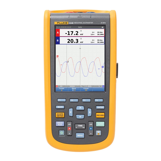
Page 22: How To Read The Screen
Waveforms. If only input A is on, you will see the Waveform input A waveform only. Displays status of attenuations, timebase, Status couplings, trigger source, and trigger slope. Displays the choices available with Button Bar 1234. hxv13.eps Fluke-Direct .com sales@GlobalTestSupply.com 1.888.610.7664... -
Page 23: Connect-And-View
The reading area shows the numeric readings of the chosen measurements on the waveform that is applied to the input jack. Figure 7, Figure 8, and Figure 9 illustrate the setups for measurements. Fluke-Direct .com sales@GlobalTestSupply.com 1.888.610.7664... - Page 24 123B/124B/125B Users Manual BB120 10 mV/A - 1 mV/A see Figure 8 item 5 see Figure 8 item 4 hxv03.eps Figure 7. Measurement Setup Fluke-Direct .com sales@GlobalTestSupply.com 1.888.610.7664...
- Page 25 Industrial ScopeMeter® Scope and Meter Mode hxv04.eps Figure 8. Correct Grounding Setup Fluke-Direct .com sales@GlobalTestSupply.com 1.888.610.7664...
- Page 26 123B/124B/125B Users Manual 10 mV/A - 1 mV/A hxv57.eps Figure 9. Temperature and Current Measurement Setup Fluke-Direct .com sales@GlobalTestSupply.com 1.888.610.7664...
-
Page 27: Inputs
Industrial ScopeMeter® Scope and Meter Mode Inputs IntellaSet™ / AutoReading The AutoReading function uses Fluke IntellaSet™ Voltage Measurements technology to enable hands-off operation to display meter For proper grounding, connect the short ground leads to readings that correspond with the shape of the waveform. -
Page 28: Measurement Type
Figure 10. AutoReading Function Push to accept the measurement type and close the menu. Confirm that the selected measurement type is the main reading. The former main reading moves to the smaller secondary reading position. Fluke-Direct .com sales@GlobalTestSupply.com 1.888.610.7664... -
Page 29: Screen Freeze
Push 4 to close the MEASURE A menu and button bar. Wait to hear the audible beep that means you have a stable reading. Repeat Step 1 to Step 4 to disable the AutoHold function. Fluke-Direct .com sales@GlobalTestSupply.com 1.888.610.7664... -
Page 30: Relative Measurements
Push 4 to close the MEASURE A menu and button bar. The relative measurement is now the main reading, and the former main measurement is now the smaller secondary reading position. Repeat Step 1 to Step 4 to disable the relative measurement. hxv14.eps Fluke-Direct .com sales@GlobalTestSupply.com 1.888.610.7664... -
Page 31: Auto Range/Manual Range
The available amplitude settings are from 5 mV/div to The waveform positions are fixed for 3-phase 200 V/div with the use of test leads. power measurements. Push to enlarge the waveform. Push to reduce the waveform. Fluke-Direct .com sales@GlobalTestSupply.com 1.888.610.7664... -
Page 32: Noise Reduction
Push 2 to open the SCOPE menu. to highlight the Type as Glitch Off. This feature will be turned off for both channel A and channel B. Push to make the change. Push 4 to exit the menu. hxv15.eps Fluke-Direct .com sales@GlobalTestSupply.com 1.888.610.7664... -
Page 33: Waveform Smoothing
Glitch detect is turned off in this mode. hxv16.eps to highlight the Type as Smooth. Both the hxv17.eps input A and input B waveforms are smoothed. Figure 11. Waveform Smoothing Push to make the change. Fluke-Direct .com sales@GlobalTestSupply.com 1.888.610.7664... -
Page 34: Reading Smoothing
Repeat the first two actions of Smoothing the Waveform, and then do the following: To display the waveform envelope: Push to open the Scope and Meter button bar. Push 2 to open the SCOPE SETTINGS menu. hxv18.eps to highlight the Type as Envelope. Fluke-Direct .com sales@GlobalTestSupply.com 1.888.610.7664... -
Page 35: Waveform Acquisition
Information area updates: To continue with the next single acquisition: Waiting Test Tool is waiting for a trigger Push and wait for another single acquisition single acquisition is triggered trigger. Hold single acquisition is complete Fluke-Direct .com sales@GlobalTestSupply.com 1.888.610.7664... -
Page 36: Slow Signals
The Test Tool does not make measurements while recording. Push to freeze the waveform in roll mode. The measurement values show only after you push . To capture longer waveform recordings, see Recorder Mode. hxv20.eps Fluke-Direct .com sales@GlobalTestSupply.com 1.888.610.7664... -
Page 37: Ac Coupling
Information Area. To optimize trigger level and slope manually: Repeatedly push until all menus and secondary button bars close. Push 2 to enable and use WXYZ to set the Trigger level and slope adjustment. Fluke-Direct .com sales@GlobalTestSupply.com 1.888.610.7664... -
Page 38: Select Trigger Parameters
1 Hz: Use WX for Trigger on either positive slope or Push to open the Scope and Meter button bar. negative slope of the chosen waveform. Push 2 to open the SCOPE SETTINGS menu. hxv21.eps hxv22.eps Fluke-Direct .com sales@GlobalTestSupply.com 1.888.610.7664... - Page 39 Autoset Settings. the function is disabled or the status is not valid. Push to open the USER > AUTOSET MENU. to highlight the Search For Signals as > 1 Hz. Push to make the change. Fluke-Direct .com sales@GlobalTestSupply.com 1.888.610.7664...
-
Page 40: Cursor Measurements
Push 2 to select the lower cursor. to move the position of the lower cursor on the waveform. hxv23.eps Note Even when the key labels are not displayed at the bottom of the screen, you can still use the arrow keys. Fluke-Direct .com sales@GlobalTestSupply.com 1.888.610.7664... -
Page 41: Vertical Cursors
Push 2 to select the left cursor. to move the position of the left cursor on the waveform. Push 2 to select the right cursor. to move the position of the right cursor on the waveform. hxv24.eps Fluke-Direct .com sales@GlobalTestSupply.com 1.888.610.7664... -
Page 42: Rise Time Measurements
A marker is shown at 10%. The reading now shows the risetime from 10%-90% of the trace amplitude and the voltage at the cursors in relation to the zero icon (-). hxv25.eps Push 3 to disable the cursors. Fluke-Direct .com sales@GlobalTestSupply.com 1.888.610.7664... -
Page 43: High Frequency Measurements With 10:1 Probe
Power and Harmonics Mode High Frequency Measurements with 10:1 Probe Probe Adjustment Fluke recommends the VP41 10:1 Probe to measure high The VP41 Probe is always adapted correctly to its inputs. frequency signals in circuits with high impedance. The High frequency adjustment is not necessary. -
Page 44: Volts/Amps/Watt Measurements
To select the type of measurement: Push 2 to select the waveform display. Push 1 to toggle between the Voltage/Current or hxv26.eps Power readings. Fluke-Direct .com sales@GlobalTestSupply.com 1.888.610.7664... - Page 45 Frequency of voltage signal on channel A Frequency Current AC value on channel B Power factor. The ratio between active power and apparent power. A<B Phase angle between voltage on channel A and current on channel B Fluke-Direct .com sales@GlobalTestSupply.com 1.888.610.7664...
-
Page 46: Harmonics Measurements
Table 7. For harmonics display when watts • Voltage measurements on Input A measurements are selected, see Table 8. • Current measurements on Input B • Power measurements calculated from Voltage measurements on Input A and Current measurements on Input B. Fluke-Direct .com sales@GlobalTestSupply.com 1.888.610.7664... - Page 47 RMS value (THD%r) or as a percentage of the fundamental (THD%f). You can select %r or %f in the Settings menu (3). The phase angle between the harmonic component and the hxv29.eps fundamental voltage. Fluke-Direct .com sales@GlobalTestSupply.com 1.888.610.7664...
- Page 48 RMS value (THD%r) or as a percentage of the fundamental (THD%f). You can select %r or %f in the Settings menu (3). hxv30.ep The phase angle between the harmonic component and the fundamental current. Fluke-Direct .com sales@GlobalTestSupply.com 1.888.610.7664...
- Page 49 RMS value (THD%r) or as a percentage of the fundamental (THD%f). You can select %r or %f in the Settings menu (1). The phase angle between the harmonic component and the fundamental current. hxv31.ep Fluke-Direct .com sales@GlobalTestSupply.com 1.888.610.7664...
-
Page 50: Zooming Harmonics
47. and to make the change. For supported bus types and protocols see Table 9. An example of the screen is shown in Table 10. Connect the inputs as shown in Figure 8, setup 4. Fluke-Direct .com sales@GlobalTestSupply.com 1.888.610.7664... - Page 51 BNC cable for bus measurements. RS-232 STL120 You can use the optional BHT190 Bushealth Test RS-485 STL120 adapter to easily connect the probe tip to a bus that uses a DB9, RJ-45, or a M12 connector. Fluke-Direct .com sales@GlobalTestSupply.com 1.888.610.7664...
-
Page 52: How To Read The Screen
Used low (LOW) and high (HIGH) test limits (LIMIT), for example 18.5 31.6V. The * indicates that one or more of the limits are not set to LIMIT * the default value. The limit does Not Apply to this bus type. hxv33.eps Fluke-Direct .com sales@GlobalTestSupply.com 1.888.610.7664... - Page 53 Data Baud Baud rate Rise Rise time as % of bit width Fall Fall time as % of bit width Distortion Jitter Jitter distortion Distortion Amplitude Amplitude distortion (AS-i bus) Signal distortion, over- and Distortion Overshoot undershoot Fluke-Direct .com sales@GlobalTestSupply.com 1.888.610.7664...
- Page 54 Test OK. Measurement results are within 80% of allowable range, see Figure 12. Warning. Measurement results are between 80% and 100% of allowable range, see Figure 12. Test failed. Measurement results are out of allowable range, see Figure 12. Fluke-Direct .com sales@GlobalTestSupply.com...
-
Page 55: How To View The Bus Waveform Screen
Push 1 to clear the persisted waveforms and restart to show the waveform. Fluke-Direct .com sales@GlobalTestSupply.com 1.888.610.7664... -
Page 56: Test Limits
From the BUSHEALTH main screen, push 1 to open the SETUP LIMITS menu. The header shows the bus type. YZWX to highlight the property for the limit. hxv36.eps Note Use 2 to set all limits to the default setting. Fluke-Direct .com sales@GlobalTestSupply.com 1.888.610.7664... -
Page 57: Recorder Mode
(as is the case in Scope and Meter mode). hxv37.eps An asterisk ( ) in the SETUP LIMITS screen indicates that a signal property has limits that differ from the default setting. Fluke-Direct .com sales@GlobalTestSupply.com 1.888.610.7664... -
Page 58: Start And Stop Meter Recording
Set Duration. To set the parameters for recording: Push to open the RECORDER SETTINGS > Push to open the Recorder button bar. DURATION menu. Push 1 to open the RECORDING SETTINGS menu. hxv39.eps Fluke-Direct .com sales@GlobalTestSupply.com 1.888.610.7664... - Page 59 The other readings show the average (AVG), the minimum (MIN), and the maximum (MAX) reading since the Recorder start and the time of the most recent change of a value. Fluke-Direct .com sales@GlobalTestSupply.com 1.888.610.7664...
-
Page 60: Cursor Measurements
Use WX to move the cursors. hxv41.eps The readings show a minimum and maximum value. These are the minimum and maximum values of the readings for the time period that represents one pixel on the display. Fluke-Direct .com sales@GlobalTestSupply.com 1.888.610.7664... -
Page 61: Zoom In/Out On Logged Meter Data
Push 3 to select Events < >. Push to open the DURATION menu. Use WX to jump between events. The readings on the top positions will mark the value at the start of the event. Fluke-Direct .com sales@GlobalTestSupply.com 1.888.610.7664... - Page 62 10. Use YZ to highlight the memory type for recording as either the internal memory of the Test Tool or an SD memory card. 11. Push to accept the memory location. 12. Push 4 when done. hxv42.eps Fluke-Direct .com sales@GlobalTestSupply.com 1.888.610.7664...
-
Page 63: Save And Recall Data Sets
SD Card memory. to highlight Save as…. Push open the Save as menu. Use this menu to name the data set. You can change the name or save the data set to the default name. Fluke-Direct .com sales@GlobalTestSupply.com 1.888.610.7664... -
Page 64: Test Sequence
No cursor keys need to be used. hxv44.eps Push to accept the setup. Only the data sets stored as a test sequence number are visible in the TEST SEQUENCE menu. Other data sets are visible when you select 3 (Recall). Fluke-Direct .com sales@GlobalTestSupply.com 1.888.610.7664... -
Page 65: Setting Recall
Push to accept the setting. Push 3 to open the Action button bar. Use the corresponding function key for the copy, move, rename, and delete actions. Fluke-Direct .com sales@GlobalTestSupply.com 1.888.610.7664... -
Page 66: Waveform Comparison
Push to select the Setup and reference waveform. The reference waveform shows on the screen as gray. The reference waveform remains on screen hxv45.eps until a setting, such as auto/manual, attenuation, or timebase, is changed. Fluke-Direct .com sales@GlobalTestSupply.com 1.888.610.7664... -
Page 67: Communication
• PC or laptop that uses FlukeView ScopeMeter software with an optical cable or wireless interface • Tablet or smartphone using Fluke Connect with WiFi interface Optical Interface Connect the Test Tool to a computer with a wired ® ®... - Page 68 For the first-time setup, push to open the Menu. to highlight USER OPTIONS. Push to open the USER OPTIONS menu. to highlight Information. Push to open the INFORMATION menu. Push 1 to open the WiFi Settings menu. Fluke-Direct .com sales@GlobalTestSupply.com 1.888.610.7664...
-
Page 69: Maintenance
Hazardous with water and get medical aid. voltage exposure is possible. • Use only the Fluke BP290 as a • Remove the input signals before you replacement battery. clean the Product. -
Page 70: 10:1 Scope Probes
Tool. Push to open the USER OPTIONS menu. Lift one side of the battery pack and remove it from the Test Tool. Install a good battery pack. Place the battery cover into position and lock. Fluke-Direct .com sales@GlobalTestSupply.com 1.888.610.7664... -
Page 71: Calibration Information
Calibration Information The Test Tool specifications are based on a 1 year calibration cycle. Recalibration must be done by qualified personnel. Contact your local Fluke representative for more information about recalibration. To find the firmware version and calibration date of your Test Tool: Push ... -
Page 72: Replaceable Parts And Accessories
(firmware) options, and nearest service center. Table 14 is a list of optional memory usage information. accessories. See Figure 1 for an illustration of parts and Push 4 to exit the menu. accessories. Fluke-Direct .com sales@GlobalTestSupply.com 1.888.610.7664... - Page 73 Industrial ScopeMeter® Replaceable Parts and Accessories Table 13. Replaceable Parts and Accessories Item (see Figure 1) Description Order Code Fluke Test Tool Rechargeable Li-ion Battery Pack BP290 Switch Mode Power Supply, Adapter/Battery Charger BC430/820 Set of two Shielded Test Leads (Red and Blue), designed for use only with ®...
- Page 74 Bushealth Test Adapter: connects the probe tip to busses that use a not shown BHT190 DB9, RJ-45, or a M12 connector Software & Cable Carrying Case Kit (Supplied with Fluke 12x/S) SCC 120B Set contains the following parts: • Screen Protector ...
-
Page 75: Tips
Push to accept the change and exit the menu. turns off after the selected time (30 seconds or 5 minutes). Note If the power adapter is connected, automatic power shutdown and the display AUTO-off function is disabled. Fluke-Direct .com sales@GlobalTestSupply.com 1.888.610.7664... -
Page 76: Autoset Options
To configure Autoset to maintain the actual input coupling ground lead. (AC or DC), continue from step 5 above: to highlight Couplings Unchanged. Push to accept the change and exit the menu. Fluke-Direct .com sales@GlobalTestSupply.com 1.888.610.7664... -
Page 77: Specifications
BB120 ............1 MΩ//24 pF with STL120 ............1 MΩ//230 pF with VP41 10:1 Probe ......... 5 MΩ//15.5 pF Sensitivity .............. 5 mV to 200 V/div Analog Bandwidth Limiter ........10 kHz Display Modes ............A, -A, B, -B Fluke-Direct .com sales@GlobalTestSupply.com 1.888.610.7664... - Page 78 Equivalent sampling ..........±(0.4 % + 0.025 time/div) Real time sampling ..........±(0.1 % + 0.025 time/div) Glitch Detection ............ ≥25 ns @ 20 ns to 60 s/div Horizontal Move ............ 12 divisions, trigger point can be positioned anywhere across the screen Fluke-Direct .com sales@GlobalTestSupply.com 1.888.610.7664...
-
Page 79: Dual Input Meter
The accuracy of all measurements is within ±(% of reading + number of counts) from 18 °C to 28 °C. Add 0.1x (specific accuracy) for each °C below 18 °C or above 28 °C. For voltage measurements with 10:1 probe, add probe uncertainty +1 %. More than one waveform period must be visible on the screen. Fluke-Direct .com sales@GlobalTestSupply.com... - Page 80 60 Hz (6 Hz with 10:1 probe) ....-1.5 % 50 Hz (5 Hz with 10:1 probe) ....-2 % 33 Hz (3.3 Hz with 10:1 probe) ....-5 % 10 Hz (1 Hz with 10:1 probe) ....-30 % Fluke-Direct .com sales@GlobalTestSupply.com 1.888.610.7664...
- Page 81 125B, 124B ............. 1 Hz, 10 Hz, 100 Hz, 1 kHz, 10 kHz, 100 kHz,1 MHz, 10 MHz, and 70 MHz 123B ..............1 Hz, 10 Hz, 100 Hz, 1 kHz, 10 kHz, 100 kHz,1 MHz, 10 MHz, and 50 MHz Frequency Range in Continuous Autoset ... 15 Hz (1 Hz) to 50 MHz Fluke-Direct .com sales@GlobalTestSupply.com...
- Page 82 Frequency Range in Continuous Autoset ... 15 Hz (1 Hz) to 30 MHz Accuracy (Logic or Pulse waveforms) @ 1 Hz to 1 MHz ..........±(0.5 % + 2 counts) @ 1 MHz to 10 MHz ........±(1.0 % + 2 counts) Full Scale Reading .......... 1000 counts Fluke-Direct .com sales@GlobalTestSupply.com 1.888.610.7664...
- Page 83 0 dBm (600 Ω /50 Ω) ........... 1 mW referenced to 600 Ω or 50 Ω dB on ..............VDC, VAC, or VAC+DC Full Scale Reading ..........1000 counts Crest Factor (CREST) Range ..............1 to 10 Accuracy.............. ±(5 % + 1 count) Full Scale Reading ..........90 counts Fluke-Direct .com sales@GlobalTestSupply.com 1.888.610.7664...
- Page 84 Purpose ............... to measure on pulse width modulated signals, like motor drive inverter outputs Principle .............. readings show the effective voltage based on the average value of samples over a whole number of periods of the fundamental frequency Accuracy ............. as Vrms for sinewave signals Fluke-Direct .com sales@GlobalTestSupply.com 1.888.610.7664...
- Page 85 Accuracy.............. ±(2 % + 5 counts) Measurement Current ......... 0.5 mA Polarity ..............+ on input A, - on COM Capacitance (CAP) Ranges ..............50 nF, 500 nF, 5 μF, 50 μF, 500 μF Accuracy.............. ±(2 % + 10 counts) Fluke-Direct .com sales@GlobalTestSupply.com 1.888.610.7664...
-
Page 86: Cursor Readout (124B, 125B)
Harmonics values in POWER QUALITY mode. Dual Vertical Lines Peak-Peak, Time Distance and Reciprocal Time Distance Readout Average, Min, Max and Time Distance Readout (in ROLL mode, instrument in HOLD) Dual Horizontal Lines High, Low and Peak-Peak Readout Fluke-Direct .com sales@GlobalTestSupply.com 1.888.610.7664... -
Page 87: Recorder
125B, 124B Record Size SD card ........15 G samples Recorded Time Span SD card ....11 hours at 500 μs/div 14 days at 20 ms/div Maximum number of events ........ 64 events on 1 channel Fluke-Direct .com sales@GlobalTestSupply.com 1.888.610.7664... -
Page 88: Power Quality (125B)
Watt ..............fund. ±(5 % + 10 counts) 31st ±(10 % + 10 counts), 51st ±(30 % + 5 counts) Frequency of fundamental ......±0.25 Hz Phase Angle ............ fund. ±3° … 51 ±15° K-factor (in Amp and Watt) ......±10 % Fluke-Direct .com sales@GlobalTestSupply.com 1.888.610.7664... -
Page 89: Field Bus Measurements (125B)
Specifications Field Bus Measurements (125B) Type Subtype Protocol AS-i NEN-EN50295 ISO-11898 Interbus S RS-422 EIA-422 RS-232 RS-232/EIA-232 Modbus RS-485 RS-485/EIA-485 Foundation Fieldbus 61158 type 1, 31.25 kBit EIA-485 Profibus 61158 type 1 RS-232 EIA-232 RS-485 EIA-485 Fluke-Direct .com sales@GlobalTestSupply.com 1.888.610.7664... -
Page 90: Miscellaneous
............32 GB for recording, 20 memory locations for saving data sets Mechanical Size ..............259 mm x 132 mm x 55 mm (10.2 in x 5.2 in x 2.15 in) Weight ..............1.4 kg (3.1 lb) including battery pack Fluke-Direct .com sales@GlobalTestSupply.com 1.888.610.7664... -
Page 91: Environmental
@ -20 °C to 60 °C (-4 °F to 140 °F) ....noncondensing Altitude Operating CAT III 600V ........3 km (10 000 feet) Operating CAT IV 600V ........2 km (6 600 feet) Storage ..............12 km (40 000 feet) Fluke-Direct .com sales@GlobalTestSupply.com 1.888.610.7664... - Page 92 USA (FCC) ............47 CFR 15 subpart B. This product is considered an exempt device per clause 15.103. Wireless Radio with Adapter Frequency Range ..........2412 MHz to 2462 MHz Output Power ............<100 mW Enclosure Protection ..........IP51, ref: EN/IEC60529 Fluke-Direct .com sales@GlobalTestSupply.com 1.888.610.7664...
- Page 93 0.01 0.02 0.05 0.1 0.2 0.5 50 100 200 FREQUENCY (kHz) hpp050.ep hpp049.eps Figure 15. Max. Input Voltage vs. Frequency for BB120 Figure 16. Safe Handling: Max. Voltage Between Test and STL120-IV Tool Reference and Earth Ground Fluke-Direct .com sales@GlobalTestSupply.com 1.888.610.7664...
- Page 94 123B/124B/125B Users Manual The Fluke 12xB series, including standard accessories, conforms to the EEC directive 2004/108/EC for EMC immunity, as defined by EN61326-1: 2006, with the addition of the table below. Trace disturbance with STL120-IV No visible Disturbance less than...