Table of Contents
Advertisement
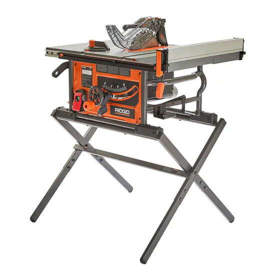
OPERATOR'S MANUAL
10 INCH PORTABLE TABLE SAW
R4540
Your saw has been engineered and manufactured to our high standard for dependability, ease of operation, and operator
safety. When properly cared for, it will give you years of rugged, trouble-free performance.
WARNING:
To reduce the risk of injury, the user must read and understand the operator's manual before using this product.
SAVE THIS MANUAL FOR FUTURE REFERENCE
Advertisement
Table of Contents

Related Manuals for RIDGID R4540


Summary of Contents for RIDGID R4540
- Page 1 OPERATOR’S MANUAL 10 INCH PORTABLE TABLE SAW R4540 Your saw has been engineered and manufactured to our high standard for dependability, ease of operation, and operator safety. When properly cared for, it will give you years of rugged, trouble-free performance.
-
Page 2: Table Of Contents
ADJUSTING THE BEVEL STOPS ......... 22 ADJUSTING THE BLADE HEIGHT........23 FUNCTIONAL DESCRIPTION SPECIFICATIONS The RIDGID #R4540 series 10 inch Portable Contractor Table ® Saw is designed for portability and high quality performance. It Max depth of cut at 90 degrees: 3 1/2 inch... -
Page 3: Features
FEATURES Blade Guard Bevel Lock Lever Flip Down Fence Throat Plate Height Adjustment Saw Blade Wheel Knob Miter Gauge Anti-Kickback Pawls Stand Extension Wing Riving Knife On/Off Switch Extension Lock Dust Chute Saw Body On Board Storage Push Stick Bevel Scale Rails Height Adjustment Rip Fence... -
Page 4: Important Safety Instructions
If you have any questions or concerns regarding the use of your tool or the contents of this manual, please stop using the tool and contact Customer Service, at RIDGID Portable and Fixed Power Tool Technical Service at (toll free) 1-888-359-4778. -
Page 5: General Power Tool Safety Warnings
GENERAL POWER TOOL SAFETY WARNINGS Read all safety warnings, instructions, illustrations and specifications provided with this power tool. Failure to follow all instructions listed below may result in electric shock, fire and/or serious injury. Save all warnings and instructions for future reference. The term “power tool”... -
Page 6: Terminology
TABLE SAW SAFETY RULES Failure to follow these rules may result in serious personal injury. SEE GENERAL POWER TOOL SAFETY SECTION OF THIS MANUAL. Read entire instruction manual before operating saw. Learning the saw’s proper applications, limitations, and specific potential hazards will greatly minimize the possibility of accidents and injury. Make sure all users are familiar with its warnings and instructions before using saw. - Page 7 TABLE SAW SAFETY RULES i. Provide auxiliary workpiece support to the rear and/or sides of the saw table for long and/or wide workpieces to keep them level. A long and/or wide workpiece has a tendency to pivot on the table’s edge, causing loss of control, saw blade binding and kickback.
-
Page 8: Saw Blade Guard, Anti-Kickback Pawls And Riving Knife Assembly
TABLE SAW SAFETY RULES SAW BLADE GUARD, ANTI-KICKBACK PAWLS AND RIVING KNIFE ASSEMBLY Your Table Saw is equipped with a Blade Guard, Anti-Kickback Kickback Pawls MUST be removed and riving knife lowered to the Pawls and Riving Knife Assembly that covers the Blade and non-through cut position marked on the Riving Knife. -
Page 9: Power Connections
Carefully inspect parts to make sure no damage occurred during shipping. If any parts are missing, damaged or Check shipping carton and machine for damage before unpacking. pre-assembled, do not assemble. Instead, call RIDGID Customer Carefully remove components in top foam layer. Remove the top ®... -
Page 10: Package Contents
UNPACKING PACKAGE CONTENTS PC10 PC11 PC12 PC13 Saw Body Anti-Kickback Pawls Stand Part 1 PC11 Fence Throat Plate Stand Part 2 PC12 10 inch Carbide Tipped Blade Open End Blade Wrench PC13 Stand Legs Miter Gauge Closed End Blade Wrench PC10 Blade Guard Assembly Push Stick... -
Page 11: Hardware Bag Contents
UNPACKING HARDWARE BAG CONTENTS 007085 005733 006510 006510 006511 005733 003640 006459 004306 M8 x 30mm (1 3/16 inch) Carriage Bolt (8) Wheel Handle Shoulder Screw (1) Flat Washer 8mm x 14mm x 1.5T (4) Height Adjustment Wheel Knob M8 Plastic Spacer (2) Combination 4mm Allen Wrench /Phillips Screwdriver M8 x 65mm Hex Socket Head Screw (2) - Page 12 UNPACKING Tools needed for assembly or adjustments. 3mm Hex Wrench 5mm Hex Wrench 13mm Combination Wrench Straight Edge Combination Square...
-
Page 13: Assembly
ASSEMBLY When lifting saw, hold it close to your body. Keep knees bent and lift with your legs, not your back. Fully assemble Saw with Stand Assembly prior to use. Stand Assembly is an integral and necessary part of the support structure for this Saw. -
Page 14: Attaching Stand To Saw
ASSEMBLY ATTACHING STAND TO SAW Place Saw Body on Stand Assembly, while aligning the screw holes in the Saw Stand with the threaded holes in the Saw Base. See Figure 5. Tighten Hex Cap Screws, with supplied Combination 4mm Allen Wrench to secure Stand Assembly to Saw. -
Page 15: Height Adjustment Knob Installation
ASSEMBLY HEIGHT ADJUSTMENT KNOB INSTALLATION Insert Wheel Handle Shoulder Screw into Height Adjustment Wheel Knob as shown in Figure 6. Tighten Shoulder Screw with Phillips Screw Driver into the Hand Wheel. Height adjustment Wheel Knob should rotate freely around Shoulder Screw when raising or lowering the Blade with the Height Adjustment Hand Wheel. -
Page 16: Throat Plate
ASSEMBLY To reduce the risk of serious injury: The Riving Knife must be installed for every through cut and for every non-through cut unless the Riving Knife THROUGH CUT would interfere with the cut. POSITION The Riving Knife provided with the Table Saw shall be thicker than the body of the matching Saw Blade provided with the Table Saw but thinner than the kerf width of that Saw Blade. -
Page 17: Anti-Kickbacks Pawls And Blade Guard
ASSEMBLY ANTI-KICKBACK PAWLS AND BLADE GUARD ANTI-KICKBACK PAWLS To reduce the risk of serious personal injury, Anti-Kickback Pawls must be in place when making a through cut. Refer to Figure 13 and locate the Anti-Kickback Pawls Mounting Slot in the middle of the top edge of the Riving Knife Slide slot in the middle of the Anti-Kickback Pawls Assembly... -
Page 18: Installing Fence
ASSEMBLY To remove the Blade Guard Assembly: Lift the Blade Guard Assembly Lock Tab to the unlocked position as seen in Figure 16. Rotate the Guard back and slide the Pin from the Riving Knife slot. FIGURE 16 INSTALLING THE FENCE The fence can be positioned on one of the three pairs of tabs. -
Page 19: On-Board Storage
ASSEMBLY ON-BOARD STORAGE Storage is located on the left side and right side of the Tool as shown in Figures 19 & 20. Left Side Storage Figure 19: Right Side Storage Figure 20: Rip Fence Blade Wrenches PC10 Push stick R i v i n g K n i fe ( w i t h B l a d e PC10 Wrenches) -
Page 20: Making Adjustments
MAKING ADJUSTMENTS ADJUSTING BLADE PARALLEL TO MITER GAUGE GROOVE (HEEL) • Blade must be parallel to miter gauge groove so that wood does not bind, resulting in kickback. Failure to do so could result in serious personal injury. • To reduce risk of injury from kickback, align rip fence to blade following any blade adjustments. - Page 21 MAKING ADJUSTMENTS If the rear of the blade was too close to combination square, place a block of wood on the right side of the blade. Lightly tap with a small hammer or rubber mallet to achieve the correct parallelism adjustment . See Figure 26. Retighten the trunnion bolts with hex wrench.
-
Page 22: Squaring The Blade Vertically
MAKING ADJUSTMENTS SQUARING THE BLADE VERTICALLY TO THE TABLE Place a combination square against the table and the side of the blade, avoiding contact with the teeth. See Figure 27. If it is not square, adjust the 0° stop as shown in Adjusting The Bevel Stops. -
Page 23: Adjusting The Blade Height
MAKING ADJUSTMENTS ADJUSTING THE BLADE HEIGHT For all through cuts, the top of the blade points should be above the workpiece and the bottom of the blade gullets are below the top surface of workpiece. For non-through cuts, the top of the blade points should be set to the depth of the cut. -
Page 24: Using Color-Coded Scales
MAKING ADJUSTMENTS USING COLOR-CODED SCALES Each corresponding scale should be used to measure the distance between the inside face of the blade to the inside face of the fence. Adjust the width of the table saw by using the table extension. Release the table “lock”... -
Page 25: Riving Knife Position And Alignment
RIVING KNIFE POSITION AND ALIGNMENT RIVING KNIFE HEIGHT SETTINGS The height of the riving knife should be adjusted based on the Lower type of cut being made. For all through cuts (when the wood Position Adjust Detents is completely severed), it should be in the raised position, with Upper Position anti-kick pawls and guard installed. -
Page 26: Riving Knife Alignment
RIVING KNIFE POSITION AND ALIGNMENT Location point for “NON-THRU CUT POSITION”. NOTE: Riving knife is located in this position for “NON-THRU” cuts NON-THROUGH and is also in this position when packaged for shipment. Location point for “THRU CUT POSITION” as shown in Figure THROUGH 37. -
Page 27: Moving The Saw
NEVER use a dull blade. A dull blade should be replaced or within reach for proper use? re-sharpened. The use of attachments and accessories not recommended Never perform freehand cutting, plunge cutting, re-sawing or by Ridgid may result in injury. ® cove cutting. -
Page 28: Dust Collector
OPERATION DUST COLLECTOR Connect a shop vacuum or dust collection hose to dust port on back of saw for best dust collection. Dust port is designed for a 2 1/2 inch vac hose. FIGURE 42 TURNING THE SAW ON AND OFF The ON/OFF paddle switch is located on the left side of the front panel of the saw. -
Page 29: Making Cuts
MAKING CUTS Failure to comply with the following warnings may result in serious personal injury. • NEVER touch the free end of the workpiece or a free piece • A rip fence should ALWAYS be used for ripping operations that is cut off, while the power is on and/or the saw blade to prevent loss of control and personal injury. -
Page 30: Rip Cuts
MAKING CUTS RIP CUTS • Rip cutting is performed predominantly in a parallel direction with this saw, and instructions are included to make with the grain of the wood. additional push sticks and other cutting aids. • Make sure blade is parallel to miter gauge slot prior to cutting. DO NOT push or hold onto the free or cut-off side of the Instructions for adjustment on page 26. -
Page 31: Crosscutting
MAKING CUTS CROSSCUTTING • Cross cutting is performed predominantly in a perpendicular miter gauge and attach workpiece to auxiliary face. For CUTTING direction with the grain of the wood. instructions about making auxiliary faces, see AIDS section on page 33 of this manual. •... -
Page 32: Compound Miter Cuts
MAKING CUTS COMPOUND MITER CUTS This is a combination of bevel crosscutting and mitering. Refer to Figure 48 and follow the instructions for both bevel crosscutting and mitering. Remember to use the right miter slot on the right side of the blade for all bevel cuts. LARGE PANEL CUTS Place workpiece supports at table height behind and/or to the side of saw to support workpiece as needed. -
Page 33: Cutting Aids And Accessories
CUTTING AIDS AND ACCESSORIES PUSH STICK In order to operate your table saw safely, you must use a push stick whenever the size or shape of the workpiece would otherwise cause your hands to be within 6 inches (152mm) of the saw blade or other cutter. A push stick is included with this saw. No special wood is needed to make additional push sticks as long as it is sturdy and long enough with no knots, checks or cracks. -
Page 34: Auxiliary Miter Gauge Facing
CUTTING AIDS AND ACCESSORIES AUXILIARY MITER GAUGE FACING An auxiliary miter gauge facing is used to increase the surface area of the miter gauge face. The use of miter gauge with auxiliary facing is the same as original miter gauge (without auxiliary facing). See Page 23 for the use of miter gauge. -
Page 35: Featherboard
CUTTING AIDS AND ACCESSORIES FEATHERBOARD Featherboards are used to keep the workpiece in contact with Select a solid piece of lumber approximately 3/4 inch thick, the fence and table (see Figure 54), and help prevent kickback. 2 1/2 inches wide and 12 inches long. Featherboards are especially useful when ripping narrow workpieces Mark the center width on one end of stock. -
Page 36: Maintenance
Specific areas which require regular maintenance include: RIVING KNIFE CLAMP PLATE: Keep this area free of dust and debris buildup. Blow out area regularly with compressed air. NOTE: If the riving knife clamp can’t move freely, have the saw serviced by authorized Ridgid service center personnel. -
Page 37: Troubleshooting
TROUBLESHOOTING For assistance with your machine, visit our website at www.RIDGID.com for a list of service centers or call RIDGID Customer Service at ® (toll free) 1-888-359-4778 or email at RidgidTableSaws@ridgidproducts.com. FAILURE TO START If your machine fails to start, check to make sure the prongs on the cord plug are making good contact in the receptacle, and check reset button on “GFI”... -
Page 38: Parts, Service Or Warranty Assistance
, Inc. All warranty communications should failure or defect resulting from misuse, abuse, neglect, alteration, ® be directed to Customer Service attn: RIDGID® Hand Held and modification or repair by other than an authorized service center Stationary Power Tool Technical Service at (toll free) 1-888-359- RIDGID branded hand held and stationary power tools. - Page 39 OPERATOR’S MANUAL 10 INCH PORTABLE CONTRACTOR TABLE SAW R4540 Customer Service Information: For parts or service, do not return this product to the store. Contact your nearest RIDGID authorized service center. Be sure to provide all relevant information when ®...