Table of Contents
Advertisement
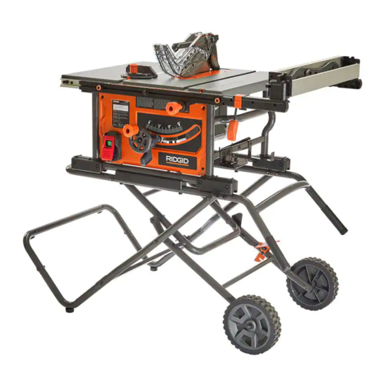
OPERATOR'S MANUAL
10 in. PORTABLE CONTRACTOR TABLE SAW
R4550
Your saw has been engineered and manufactured to our high standard for dependability, ease of operation, and operator
safety. When properly cared for, it will give you years of rugged, trouble-free performance.
WARNING:
To reduce the risk of injury, the user must read and understand the operator's manual before using this product.
SAVE THIS MANUAL FOR FUTURE REFERENCE
Advertisement
Table of Contents

Related Manuals for RIDGID R4550


Summary of Contents for RIDGID R4550
- Page 1 OPERATOR’S MANUAL 10 in. PORTABLE CONTRACTOR TABLE SAW R4550 Your saw has been engineered and manufactured to our high standard for dependability, ease of operation, and operator safety. When properly cared for, it will give you years of rugged, trouble-free performance.
-
Page 2: Table Of Contents
ADJUSTING THE BLADE HEIGHT ........25 CHANGING THE BEVEL ............25 FUNCTIONAL DESCRIPTION SPECIFICATIONS The RIDGID #R4550 10 inch Portable Contractor Table Saw is ® designed for portability and high quality performance. It includes: Max depth of cut at 90°: 3 ½ inch... -
Page 3: Features
FEATURES Back View Blade Guard Rails On Board Storage Throat Plate Height Adjustment Wheel Knob Miter Gauge Extension Wing Height Adjustment Handwheel Riving Knife Rip Fence Bevel Lock Lever Anti-Kickback Pawls Push Stick Stand Dust Chute Extension Lock On/Off Switch Bevel Scale Saw Body... -
Page 4: Important Safety Instructions
If you have any questions or concerns regarding the use of your tool or the contents of this manual, please stop using the tool and contact Customer Service, at RIDGID Portable and Fixed Power Tool Technical Service at (toll free) 1-888-359-4778. -
Page 5: General Power Tool Safety Warnings
GENERAL POWER TOOL SAFETY WARNINGS Read all safety warnings, instructions, illustrations and specifications provided with this power tool. Failure to follow all instructions listed below may result in electric shock, fire and/or serious injury. Save all warnings and instructions for future reference. The term “power tool”... -
Page 6: Terminology
TABLE SAW SAFETY RULES Failure to follow these rules may result in serious personal injury. SEE GENERAL POWER TOOL SAFETY SECTION OF THIS MANUAL. Read entire instruction manual before operating saw. Learning the saw’s proper applications, limitations, and specific potential hazards will greatly minimize the possibility of accidents and injury. Make sure all users are familiar with its warnings and instructions before using saw. - Page 7 TABLE SAW SAFETY RULES c. Never use the mitre gauge to feed the workpiece when ripping and do not use the rip fence as a length stop when cross cutting with the miter gauge. Guiding the workpiece with the rip fence and the mitre gauge at the same time increases the likelihood of saw blade binding and kickback.
-
Page 8: Saw Blade Guard, Anti-Kickback Pawls And Riving Knife
TABLE SAW SAFETY RULES k. When restarting the saw with the saw blade in the workpiece, centre the saw blade in the kerf so that the saw teeth are not engaged in the material. If the saw blade binds, it may lift up the workpiece and cause kickback when the saw is restarted. -
Page 9: Kickbacks
TABLE SAW SAFETY RULES KICKBACKS Plastic and composite materials (like hardboard) may be cut Kickbacks can cause serious injury. A kickback occurs when a part on your saw. However, since these are usually quite hard and of the workpiece binds between the saw blade and the rip fence, slippery, the anti-kickback pawls may not stop a kickback. -
Page 10: Power Connections
Lay out all parts on a piece of occurred during shipping. If any parts are missing, damaged or pre-assembled, DO NOT assemble. Instead, call RIDGID cardboard or other clean, flat surface. THE SAW STAND WILL ®... -
Page 11: Package Contents Description
UNPACKING PC10 PC11 PC12 PC13 PC14 PC15 PC16 PC17 PC18 PACKAGE CONTENTS DESCRIPTION Wheels (2) PC13 Saw Body Miter Gauge Support Spreader Bar PC14 Stand Handle Push Stick Throat Plate PC15 Pedal Assembly Left Support Tube Open End Blade Wrench PC16 Upper Stand Assembly Fence... -
Page 12: Contents Of Hardware Bags
UNPACKING 003380 003570 HP10 HP11 CONTENTS OF HARDWARE BAGS M6 x 50mm (1 15/16 inch) Hex Bolt (2) Height Adjustment Wheel Knob Plastic Spacer (8) Combination 4mm Allen Wrench /Phillips Screwdriver M8 Locknut (12) Fence Adjustments Knob M8 x 75mm (2 15/16 inch) Carriage Screw (4) M6 X 25L Hex Socket Round Head Screw HP10 M8 x 37mm (1 15/32 inch) Carriage Screw (4) -
Page 13: Assembly
ASSEMBLY TOOLS NEEDED FOR ASSEMBLY OR ADJUSTMENTS. 3mm Hex Key 5mm Hex Key 13mm Combination Wrench Straight Edge Combination Square • Assemble stand with saw upside down in box, then stand for final assembly. • Stand assembly is an integral and necessary part of the Support Structure for this Saw. -
Page 14: Assembling The Stand
ASSEMBLY ASSEMBLING THE STAND First remove Nut and outer Washer on each side of the 1/2 inch or 13mm wrench Pedal Assembly . Then attach the Wheels and place the Washer and Nut back on each side, as shown in Figure 2 . Be sure not to over-tighten the Nut. - Page 15 ASSEMBLY With Table saw still in Lower Packing Tray, attach Stand Handle to Tubular Base of Saw with M8x35mm Carriage Screw and M8 Locknut . See Figure 6. NOTE: Square and round holes can be aligned together. Figure 6 Attach Leg Assembly to the Upper Leg Assembly. Insert Plastic Spacer between Legs and secure with M8 x 75mm Carriage Screw...
-
Page 16: Height Adjustment Knob Installation
ASSEMBLY Unlock the Bevel Lock and rotate the Motor Assembly enough to remove the Shipping Foam protecting the Saw Motor as shown in Figure 10. Figure 10 Once the saw is upright disengage the pedal, push down on the handles until the catch is engaged, and then continue the remaining assembly steps. -
Page 17: Installing The Blade
ASSEMBLY INSTALLING THE BLADE PC16 Raise the Motor/Arbor Assembly to the upper most position PC17 to provide easy access to Riving Knife Lock Lever and Arbor Assembly. Ensure Riving Knife Lock Lever is in unlock position. See Figure 14. Detach the on-board Wrenches located on the right side of UNLOCK UNLOCK the Saw by loosening and removing M8 Wing Nut. -
Page 18: Throat Plate
ASSEMBLY To reduce the risk of serious injury, The Riving Knife MUST be installed for every through cut and for every non-through cut unless the Riving Knife THROUGH CUT THROUGH CUT would interfere with the cut. POSITION POSITION The Riving Knife provided with the table saw shall be thicker than the body of the matching Saw Blades provided with the Table Saw but thinner than the kerf width of that Saw Blade. -
Page 19: Anti-Kickbacks Pawls
ASSEMBLY ANTI-KICKBACK PAWLS AND BLADE GUARD ANTI-KICKBACK PAWLS To reduce the risk of serious personal injury, Anti-Kickback Pawls MUST be in place when making a through cut. PC12 Refer to Figure 20 and locate the Anti-Kickback Pawls mounting slot in the middle of the top edge of the Riving Knife Slide slot in the middle of the Anti-Kickback Pawls Assembly along the top of the Riving Knife until the Press... -
Page 20: Installing The Fence
ASSEMBLY To remove the Blade Guard Assembly: Lift the Lock Tab to the unlocked position. Rotate the Guard back and slide the Locating Pin from the Riving Knife slot. See Figure 23. Figure 23 INSTALLING THE FENCE The fence can be positioned on one of the three pairs of tabs. Two on the right side of the blade and one on the left side. -
Page 21: On-Board Storage
ASSEMBLY ON-BOARD STORAGE Storage is located on the Left side, Right side of the machine as shown in Figures 27 & 28. PC10 Push Stick Anti-kickback Pawls (Stored behind Blade Guard Assembly) PC12 Open End Wrench PC16 Closed End Wrench PC17 Blade guard assembly PC11... -
Page 22: Making Adjustments
MAKING ADJUSTMENTS LEVELING THE THROAT PLATE To install throat plate, slip tab into slot at back of saw and push down to secure in place. Leveling screws Leveling screws See Figures 31. NOTE: There are four screws pre-assembled to the throat plate that are used for leveling the throat plate if necessary. - Page 23 MAKING ADJUSTMENTS If the distances are different: Loosen the front trunnion bolts using a 5mm Hex Wrench, found below the table top. See Figure 34. Figure 34 Loosen the rear trunnion bolts using a 5mm Hex Wrench, found below the table top. See Figure 35. Figure 35 If the rear of the blade was too close to combination square, place a block of wood on the right side of the...
-
Page 24: Squaring The Blade Vertically To The Table
MAKING ADJUSTMENTS SQUARING THE BLADE VERTICALLY TO THE TABLE Place a combination square against the table and the side of the blade, avoiding contact with the teeth. See Figure 37. If it is not square, adjust the 0° stop as shown in ADJUSTING THE BEVEL STOPS. -
Page 25: Adjusting The Blade Height
MAKING ADJUSTMENTS ADJUSTING THE BLADE HEIGHT For all through cuts, the top of the blade teeth should be above the workpiece and the bottom of the blade gullets UNLOCK UNLOCK are below the top surface of workpiece. For non-through cuts, the top of the blade points should be set to the depth of the cut. -
Page 26: Using Color Coded Scales
MAKING ADJUSTMENTS USING COLOR CODED SCALES BLACK SCALE W/ BLACK SCALE W/ WHITE NUMBERS WHITE NUMBERS Each corresponding scale should be used to measure the distance between the inside face of the blade to the inside face of the fence. CLEAR CLEAR BLACK TAB... -
Page 27: Engaging The Flip Down Fence
MAKING ADJUSTMENTS ENGAGING THE FLIP DOWN FENCE When working with large pieces of material that extend beyond the table surface flip the work piece support towards the blade side of the table to provide proper support. Locate work piece support on right side of fence. Push up on Flip Fence and flip over top of Fence and toward the blade side of Fence. -
Page 28: Riving Knife Height Settings
RIVING KNIFE POSITION AND ALIGNMENT RIVING KNIFE HEIGHT SETTINGS See Figure 47. ADJUST LOWER The height of the riving knife should be adjusted based on the POSITION LOCKED type of cut being made. For all through cuts (when the wood is DETENTS completely severed), it should be in the raised position, with anti- UPPER POSITION... -
Page 29: Parallel Alignment
RIVING KNIFE POSITION AND ALIGNMENT RIVING KNIFE ALIGNMENT Parallel Alignment The plane of the riving knife is parallel to the plane of the blade but the riving knife and the blade are not in line with each other. If a parallel adjustment is required use Figure 48 and Figure 49 to make the following adjustments: Loosen the two hex socket head set screws using... -
Page 30: Operation
Never perform freehand cutting, plunge cutting, re-sawing or within reach for proper use? cove cutting. The use of attachments and accessories not recommended by Ridgid may result in injury. ® Replace or sharpen the anti-kick pawls when the points become dull. -
Page 31: Turning The Saw On And Off
OPERATION TURNING THE SAW ON AND OFF The ON/OFF paddle switch is located on the left side of the front panel of the saw. Press the green ON button. Press the switch down to turn the saw OFF. When not in use, the saw should be turned off and the power switch locked out to prevent unauthorized use. -
Page 32: Making Cuts
MAKING CUTS Failure to comply with the following warnings may result in serious personal injury. • NEVER touch the free end of the workpiece or a free piece A rip fence should ALWAYS be used for ripping operations • to prevent loss of control and personal injury. ALWAYS lock that is cut off, while the power is on and/or the saw blade is the fence to the rail. -
Page 33: Rip Cuts
MAKING CUTS RIP CUTS • Rip cutting is performed predominantly in a parallel direction Use the push stick and any other cutting aids, as needed, with the grain of the wood. to hold the workpiece against the table and fence, and push the workpiece past the blade. -
Page 34: Crosscutting
MAKING CUTS CROSSCUTTING a larger workpiece, or attach an auxiliary face to the miter gauge and attach workpiece to auxiliary face, For • Cross cutting is performed predominantly in a perpendicular instructions about making auxiliary faces, see Cutting Aids direction with the grain of the wood. section on page 36 of this manual. -
Page 35: Compound Miter Cuts
MAKING CUTS COMPOUND MITER CUTS This is a combination of bevel crosscutting and mitering. Refer to Figure 60 and follow the instructions for both bevel crosscutting and mitering. Remember to use the right miter slot on the right side of the blade for all bevel cuts. LARGE PANEL CUTS Place workpiece supports at the same height as the saw table behind saw to support the cut workpiece, and alongside of saw, as... -
Page 36: Cutting Aids And Accessories
CUTTING AIDS AND ACCESSORIES PUSH STICK In order to operate your table saw safely, you MUST use a push minimum length, 15.7 inches (400mm), with different size notches stick whenever the size or shape of the workpiece would otherwise for different workpiece thicknesses. cause your hands to be within 6 inches (152mm) of the saw blade or other cutter. -
Page 37: Auxiliary Fence (Flip Down)
CUTTING AIDS AND ACCESSORIES FLIP DOWN FENCE Use the flip down fence when cutting thin stock in which the blade guard would normally interfere with the fence to make the desired cut. To utilize this flip down feature for small, narrow cuts, you must slide the flip down part of the fence underneath the blade guard, so that the blade is still covered safely by the blade guard. -
Page 38: Featherboard
CUTTING AIDS AND ACCESSORIES FEATHERBOARD Featherboards are used to keep the workpiece in contact Select a solid piece of lumber approximately 3/4 inch thick, with the fence and table Figure 66, and help prevent kickback. 2 1/2 inches wide and 12 inches long. Featherboards are especially useful when ripping small workpieces Mark the center width on one end of stock. -
Page 39: Maintenance
Specific areas which require regular maintenance include: RIVING KNIFE CLAMP PLATE: Keep this area free of dust and debris buildup. Blow out area regularly with compressed air. RIDGID authorized service center NOTE: If the riving knife clamp can’t move freely, have the saw serviced by authorized ®... -
Page 40: Accessories
® should be used with this product. TROUBLESHOOTING For assistance with your machine, visit our website at www.RIDGID.com for a list of service centers or call RIDGID Customer Service at ® (toll free) 1-888-359-4778 or email at RidgidTableSaws@ridgidproducts.com. -
Page 41: Parts, Service Or Warranty Assistance
® be directed to Customer Service attn: RIDGID Stationary Power repair by other than an authorized service center for RIDGID ® ® Tool Technical Service at (toll free) 1-888-359-4778. branded stationary power tools. Consumable accessories pro vided... - Page 42 OPERATOR’S MANUAL 10 in. PORTABLE CONTRACTOR TABLE SAW R4550 Customer Service Information: For parts or service, do not return this product to the store. Contact your nearest RIDGID authorized service center. Be sure to provide all relevant information when ®...