Table of Contents
Advertisement
Quick Links
We advise you to read this manual carefully, which contains all the instructions for
maintaining the appliance's aesthetic and functional qualities.
For further information on the product: www.smeg.com
Contents
4
4
5
5
5
6
6
6
7
7
8
8
9
9
11
11
12
12
13
14
15
16
17
22
22
22
23
23
24
24
26
27
29
29
33
3
Advertisement
Table of Contents

Related Manuals for Smeg SUK92CMX


Summary of Contents for Smeg SUK92CMX
-
Page 1: Table Of Contents
4.7 Vapor Clean 4.8 Extraordinary maintenance 5 Installation 5.1 Positioning 5.2 Electrical connection We advise you to read this manual carefully, which contains all the instructions for maintaining the appliance’s aesthetic and functional qualities. For further information on the product: www.smeg.com... -
Page 2: Instructions
Instructions 1 Instructions • Do not try to repair the appliance yourself or without the intervention 1.1 General safety instructions of a qualified technician. • If the power supply cable is Risk of personal injury damaged, contact technical • During use the appliance and its support immediately and they will accessible parts become very hot. -
Page 3: Manufacturer Liability
Instructions • People who have pacemakers or 1.3 Appliance purpose other similar devices fitted must • This appliance is intended for cooking make sure that the operation of food in the home environment. Every other use is considered improper. these devices is not jeopardised by the inductive field, whose •... -
Page 4: Identification Plate
Instructions 1.7 How to read the user manual • Deliver the appliance to the appropriate recycling centre for electrical and This user manual uses the following reading electronic equipment waste, or return it to conventions: the retailer when purchasing an Instructions equivalent product, on a one for one basis. -
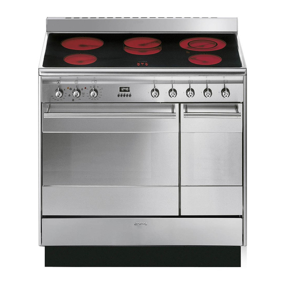
Page 5: Description
Description 2 Description 2.1 General Description 1 Cooking hob 6 Auxiliary oven door 2 Control panel 7 Fan 3 Oven light 8 Storage compartment 4 Seal Rack/tray support frame shelf 5 Main oven door... -
Page 6: Cooking Hob
Description 2.2 Cooking hob Zone Outside diameter (mm) Max. power draw (W)* Inside diameter (mm) Max. power draw (W)* 1200 2000 oval plate 2200 1400 2000 Power levels are approximate and can vary according to the pan used or the settings made. 2.3 Control panel 1 Main oven temperature knob 3 Main oven function knob... -
Page 7: Other Parts
Description for specific cooking types (see “Functions Cooling fan list”). The fan cools the oven and comes into operation during cooking. 5 Auxiliary oven indicator light The fan causes a steady outflow of air that The indicator light comes on to indicate that exits from the rear of the appliance and the oven is heating up. - Page 8 Description Oven tray Rack Useful for collecting fat from foods placed Useful for supporting containers with food on the rack above. during cooking. Tray rack Scraper Useful for cleaning the hob. The accessories intended to come into contact with food are made of materials that comply with the provisions of current legislation.
-
Page 9: Use
3 Use Improper use Risk of damage to surfaces 3.1 Instructions High temperature inside the oven • Do not cover the bottom of the oven during use cavity with aluminium or tin foil sheets. Danger of burns • If you wish to use greaseproof paper, place it so that it will not interfere with the •... -
Page 10: First Use
Description Oven cavity High temperature inside the oven during use 4. Heat the empty oven at the maximum temperature to burn off any residues left Danger of fire or explosion by the manufacturing process. • Do not spray any spray products near the appliance. -
Page 11: Using The Hob
Racks and trays 3.4 Using the hob Racks and trays have to be inserted into the Residual heat side guides until they come to a complete stop. Improper use • The mechanical safety locks that prevent Danger of burns the rack from being taken out accidentally have to face downwards •... -
Page 12: Using The Storage Compartment
Double heating zones • Make sure that the pressure cooker contains enough liquid as, if there is not To turn on the double heating zones, enough and it overheats, this may cause turn the knob to the maximum value and damage to both the pressure cooker and then to the symbols When... -
Page 13: Using The Oven
3.6 Using the oven Grill The heat coming from the grill Switching on the oven element gives perfect grilling results To switch on the oven: above all for thin and medium 1. Select the cooking function using the thickness meat and, in combination with the rotisserie (where fitted), function knob. -
Page 14: Cooking Advice
Advice for cooking with the Grill and the Fan with circulaire Fan with grill The combination of the fan and the • Meat can be grilled even when it is put circulaire heating element into the cold oven or into the preheated (incorporated in the rear of the oven if you wish to change the effect of oven) allows you to cook different... -
Page 15: Programmer Clock
• While cooking desserts or vegetables, 3.8 Programmer clock excessive condensation may form on the glass. In order to avoid this, open the door very carefully a couple of times while cooking. Advice for defrosting and proving • Place frozen foods without their packaging in a lidless container on the first shelf of the oven. - Page 16 Timed cooking Setting the time Timed cooking is the function If the time is not set, the oven will which allows a cooking operation not switch on. to be started and then ended after a specific length of time set by the On the first use, or after a power failure, the user.
- Page 17 4. Wait approx. 5 seconds without pressing 6. Press the keys at the same any key in order for the function to time to reset the programmer clock. activate. The current time and the symbols will appear on the It is not possible to set a cooking time of more than 10 hours.
- Page 18 3. Wait approx. 5 seconds without pressing Minute minder timer any key to finish setting the minute The minute minder timer does not minder. The current time and the symbols stop the cooking operation but appear on the display. rather informs the user when the set time has run out.
- Page 19 Main oven cooking information table Runner Temperature Food Weight (Kg) Function position from Time (minutes) (°C) the bottom Lasagne 3 - 4 Static 220 - 230 45 - 50 Pasta bake 3 - 4 Static 220 - 230 45 - 50 Roast veal Turbo 180 - 190...
-
Page 20: Cleaning And Maintenance
Cleaning and maintenance 4 Cleaning and maintenance Cleaning the glass ceramic hob Smudges from aluminium-based pans can 4.1 Instructions be easily cleaned off with a cloth dampened in vinegar. Improper use After cooking, remove any burnt residues Risk of damage to surfaces with the scraper provided;... -
Page 21: Removing The Door
Cleaning and maintenance surface with a clean cloth. Make sure that 2. Grasp the door on both sides with both there is no detergent left on the cooking hands, lift it forming an angle of around surface as it might undergo an aggressive 30°... -
Page 22: Removing The Internal Glass Panes
Cleaning and maintenance 4.5 Removing the internal glass 5. Reposition the internal glass pane. Take panes care to centre and insert the 4 pins into their housings in the oven door by For easier cleaning the door internal glass applying slight pressure. panes can be disassembled. - Page 23 Cleaning and maintenance Removing racks/trays support frames Cleaning the top section (main oven) Removing the guide frames enables the The oven cavity is fitted with a tilting heating sides to be cleaned more easily. This element which facilitates cleaning the top operation should be performed each time part (roof) of the oven.
-
Page 24: Vapor Clean
Cleaning and maintenance 4.7 Vapor Clean • Spray a water and washing up liquid solution inside the oven using a spray Vapor Clean is an assisted nozzle. Direct the spray against the side cleaning procedure which walls, upwards, downwards and facilitates the removal of dirt. -
Page 25: Extraordinary Maintenance
Cleaning and maintenance End of the Vapor Clean cycle 4.8 Extraordinary maintenance 4. Open the door and wipe away the less Removing and replacing the oven seal stubborn dirt with a microfibre cloth. To remove the oven seal: 5. Use an anti-scratch sponge with brass •... - Page 26 Cleaning and maintenance Seal maintenance tips 4. Slide out and remove the light bulb. The seal should be soft and elastic. • To keep the seal clean, use a non- abrasive sponge and lukewarm water to wash it. Replacing the internal light bulb Live parts Danger of electrocution Do not touch the halogen lamp...
-
Page 27: Installation
Installation 5 Installation General information This appliance may be installed next to 5.1 Positioning walls, one of which must be higher than the worktop, at a minimum distance of 50 mm Heavy appliance from the side of the appliance, as shown in Crushing hazard figures A and C relative to the installation classes. - Page 28 Installation Positioning and levelling Heavy appliance Risk of damage to the appliance • Insert the front feet first and then the rear ones. • After making the gas and electrical connections, screw on the four feet supplied with the appliance. B - Class 2 subclass 1 (Built-in appliance) The appliance must sit level on the floor to...
- Page 29 Installation 3. Assemble the fastening bracket. Fastening to the wall The anti-tip devices must be installed in order to prevent the appliance tipping over. 1. Screw the wall fastening plate to the rear of the appliance. 4. Align the base of the hook on the fastening bracket with the base of the slot on the wall fastening plate.
- Page 30 Installation 5. Align the base of the fastening bracket 7. Move the bracket onto the wall and with the ground and tighten the screws to mark the position of the holes to be fix the measurements. drilled in the wall. 6.
-
Page 31: Electrical Connection
Installation 5.2 Electrical connection Assembling the upstand The upstand provided is an Power voltage integral part of the product. It must Danger of electrocution be fastened to the appliance prior to installation. • Have the electrical connection performed by authorised technical The upstand must always be positioned and personnel. - Page 32 Installation The appliance can work in the following Fixed connection modes: Fit the power line with an omnipolar circuit • 220-240 V 1N~ breaker in compliance with installation regulations. The circuit breaker should be located near the appliance and in an easily reachable position.