Table of Contents
Advertisement
We advise you to read this manual carefully, which contains all the instructions for
maintaining the appliance's aesthetic and functional qualities.
For further information on the product: www.smeg.com
Contents
4
4
5
5
5
6
6
6
7
7
8
8
9
10
12
12
13
13
14
15
15
17
18
23
23
23
24
24
25
25
27
28
30
30
33
37
41
3
Advertisement
Table of Contents

Related Manuals for Smeg SUK92MX9


Summary of Contents for Smeg SUK92MX9
-
Page 1: Table Of Contents
5.2 Adaptation to different types of gas 5.3 Positioning 5.4 Electrical connection We advise you to read this manual carefully, which contains all the instructions for maintaining the appliance’s aesthetic and functional qualities. For further information on the product: www.smeg.com... -
Page 2: Instructions
Instructions 1 Instructions • Do not modify this appliance. • Do not insert pointed metal 1.1 General safety instructions objects (cutlery or utensils) into the slots in the appliance. Risk of personal injury • Do not try to repair the appliance •... -
Page 3: Manufacturer Liability
Instructions • Use wooden or plastic utensils. 1.3 Appliance purpose • Do not seat on the appliance. • This appliance is intended for cooking • Do not use steam jets for cleaning food in the home environment. Every other use is considered improper. the appliance. -
Page 4: Identification Plate
Instructions Our appliances are packed in non- 1.7 How to read the user manual polluting and recyclable materials. This user manual uses the following reading • Deliver the packing materials to the conventions: appropriate recycling centre. Instructions Plastic packaging General information on this user Danger of suffocation manual, on safety and final disposal. -
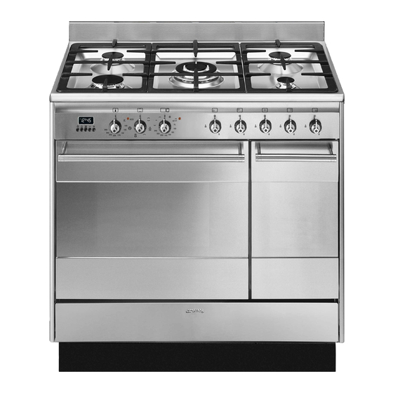
Page 5: Description
Description 2 Description 2.1 General Description 1 Cooking hob 6 Auxiliary oven door 2 Control panel 7 Fan 3 Oven light 8 Storage compartment 4 Seal Rack/tray support frame shelf 5 Main oven door... -
Page 6: Cooking Hob
Description 2.2 Cooking hob AUX = Auxiliary R = Rapid SR = Semi-rapid UR = Ultra rapid 2.3 Control panel 1 Main oven temperature knob 3 Main oven function knob This knob allows you to select the cooking The oven's various functions are suitable for temperature. -
Page 7: Other Parts
Description 2.4 Other parts 5 Auxiliary oven indicator light The indicator light comes on to indicate that Shelves the oven is heating up. It turns off as soon as The appliance features shelves to position it reaches the set temperature. It flashes trays and racks at different heights. -
Page 8: Available Accessories
Description 2.5 Available accessories Rack Some models are not provided with all accessories. Tray rack Useful for supporting containers with food during cooking. Deep tray To be placed over the top of the oven tray; for cooking foods which may drip. Useful for collecting fat from foods placed on the rack above and for cooking pies, pizzas and baked desserts. - Page 9 Description Oven tray Ring reducers Useful when using small cookware. WOK reduction pan stand Useful when using a wok. The accessories intended to come Useful for collecting fat from foods placed into contact with food are made of on the rack above. materials that comply with the provisions of current legislation.
-
Page 10: Use
3 Use Improper use Risk of damage to surfaces 3.1 Instructions High temperature inside the oven • Do not cover the bottom of the oven during use cavity with aluminium or tin foil sheets. Danger of burns • If you wish to use greaseproof paper, place it so that it will not interfere with the •... -
Page 11: First Use
Oven cavity High temperature inside the oven during use 4. Heat the empty oven at the maximum temperature to burn off any residues left Danger of fire or explosion by the manufacturing process. • Do not spray any spray products near the appliance. -
Page 12: Using The Hob
Racks and trays 3.4 Using the hob All the appliance’s control and monitoring Racks and trays have to be inserted into the devices are located together on the front side guides until they come to a complete panel. The burner controlled by each knob stop. -
Page 13: Using The Storage Compartment
3.5 Using the storage compartment Correct positioning of the flame- spreader crowns and burner caps The storage compartment is at the bottom of the cooker. To open it, pull the handle Before lighting the hob burners, make sure towards you. It can be used to store that the flame-spreader crowns are cookware or metallic objects necessary correctly positioned in their housings with... - Page 14 Functions list Lower element Fan with grill The heat coming just from the The air produced by the fan softens the strong heatwave generated by bottom allows you to complete the the grill, grilling perfectly even very cooking of foods that require a thick foods.
-
Page 15: Cooking Advice
• Use a meat thermometer when roasting meat, or simply press on the roast with a Fan with circulaire spoon. If it is hard, it is ready; If not, it The combination of the fan and the needs another few minutes cooking. circulaire heating element Advice for cooking with the Grill and the (incorporated in the rear of the... -
Page 16: Programmer Clock
• If the dessert collapses when it comes 3.8 Programmer clock out of the oven, on the next occasion reduce the set temperature by about 10°C, selecting a longer cooking time if necessary. • While cooking desserts or vegetables, excessive condensation may form on the glass. - Page 17 Timed cooking Setting the time Timed cooking is the function If the time is not set, the oven will which allows a cooking operation not switch on. to be started and then ended after a specific length of time set by the On the first use, or after a power failure, the user.
- Page 18 4. Wait approx. 5 seconds without pressing 6. Press the keys at the same any key in order for the function to time to reset the programmer clock. activate. The current time and the symbols will appear on the It is not possible to set a cooking time of more than 10 hours.
- Page 19 minder. The current time and the symbols Minute minder timer appear on the display. The minute minder timer does not stop the cooking operation but It is not possible to set a cooking rather informs the user when the set time of more than 24 hours.
- Page 20 Main oven cooking information table Runner Temperature Food Weight (Kg) Function position from Time (minutes) (°C) the bottom Lasagne 3 - 4 Static 220 - 230 45 - 50 Pasta bake 3 - 4 Static 220 - 230 45 - 50 Roast veal Turbo 180 - 190...
-
Page 21: Cleaning And Maintenance
Cleaning and maintenance 4 Cleaning and maintenance 2. Rinse thoroughly. 3. Dry with a soft cloth or a microfibre cloth. 4.1 Instructions Cleaning the hob grids, flame-spreader Improper use crowns and burner caps Risk of damage to surfaces 1. Remove the components from the hob. 2. -
Page 22: Removing The Door
Cleaning and maintenance Cleaning the oven cavity 2. Grasp the door on both sides with both hands, lift it forming an angle of around In order to keep your oven in the best 30° and remove it. possible condition, clean it regularly after letting it cool down. -
Page 23: Removing The Internal Glass Panes
Cleaning and maintenance 4.5 Removing the internal glass 5. Reposition the internal glass pane. Take panes care to centre and insert the 4 pins into their housings in the oven door by For easier cleaning the door internal glass applying slight pressure. panes can be disassembled. - Page 24 Cleaning and maintenance Removing racks/trays support frames Cleaning the top section (main oven) Removing the guide frames enables the The oven cavity is fitted with a tilting heating sides to be cleaned more easily. This element which facilitates cleaning the top operation should be performed each time part (roof) of the oven.
-
Page 25: Vapor Clean
Cleaning and maintenance 4.7 Vapor Clean • Spray a water and washing up liquid solution inside the oven using a spray Vapor Clean is an assisted nozzle. Direct the spray against the side cleaning procedure which walls, upwards, downwards and facilitates the removal of dirt. -
Page 26: Extraordinary Maintenance
Cleaning and maintenance End of the Vapor Clean cycle 4.8 Extraordinary maintenance 4. Open the door and wipe away the less Removing and replacing the oven seal stubborn dirt with a microfibre cloth. To remove the oven seal: 5. Use an anti-scratch sponge with brass •... - Page 27 Cleaning and maintenance 4. Slide out and remove the light bulb. Replacing the internal light bulb Live parts Danger of electrocution • Unplug the appliance. The oven is fitted with a 40W light bulb. Do not touch the halogen lamp directly with your fingers, but wrap 1.
-
Page 28: Installation
Installation 5 Installation Connection with a rubber hose Verify that all following conditions are met: 5.1 Gas connection • the hose is fixed to the hose connection with safety clamps; Gas leak • no part of the hose is in contact with hot Danger of explosion walls (max. - Page 29 Installation After having tightened the hose Connection with a steel hose with connector(s), push the gas hose 6 onto the bayonet fitting hose connector and secure it with the clamp 5 Carry out the connection to the gas mains that is compliant with the standard in force. using a steel hose with bayonet fitting compliant with B.S.
- Page 30 Installation The room must be kept adequately ventilated in order to eliminate the heat and humidity produced by cooking: In particular, after prolonged use, you are recommended to open a window or to increase the speed of any fans. Extraction of the combustion products The combustion products may be extracted by means of hoods connected to a natural draught chimney whose efficiency is certain...
-
Page 31: Adaptation To Different Types Of Gas
Installation A Single natural draught chimney Adjusting the minimum setting for natural or town gas B Single chimney with extractor fan C Directly outdoors with wall- or window- Light the burner and turn it to the minimum mounted extractor fan position. - Page 32 Installation Gas types and Countries Gas types IT GB-IE FR-BE DE RU DK 1 Natural Gas G20 20 mbar • • • • • • • • • G20/25 20/25 mbar • 2 Natural Gas G20 25 mbar • 3 Natural Gas G25 25 mbar •...
- Page 33 Installation Burner and nozzle characteristics tables 1 Natural Gas G20 Rated heating capacity (kW) Nozzle diameter (1/100 mm) Pre-chamber (printed on nozzle) (-6) Reduced flow rate (W) 1600 2 Natural gas G20 – 25 mbar Rated heating capacity (kW) Nozzle diameter (1/100 mm) Pre-chamber (printed on nozzle) (-1) Reduced flow rate (W)
- Page 34 Installation 8 LPG G30/31 Rated heating capacity (kW) Nozzle diameter (1/100 mm) Pre-chamber (printed on nozzle) Reduced flow rate (W) 1600 Rated flow rate G30 (g/h) Rated flow rate G31 (g/h) 9 LPG G30/G31 – 37 mbar Rated heating capacity (kW) Nozzle diameter (1/100 mm) Pre-chamber (printed on nozzle) Reduced flow rate (W)
-
Page 35: Positioning
Installation 5.3 Positioning General information This appliance may be installed next to Heavy appliance walls, one of which must be higher than the Crushing hazard worktop, at a minimum distance of 50 mm from the side of the appliance, as shown in •... - Page 36 Installation Positioning and levelling Heavy appliance Risk of damage to the appliance • Insert the front feet first and then the rear ones. • After making the gas and electrical connections, screw on the four feet supplied with the appliance. B - Class 2 subclass 1 (Built-in appliance) The appliance must sit level on the floor to...
- Page 37 Installation 3. Assemble the fastening bracket. Fastening to the wall The anti-tip devices must be installed in order to prevent the appliance tipping over. 1. Screw the wall fastening plate to the rear of the appliance. 4. Align the base of the hook on the fastening bracket with the base of the slot on the wall fastening plate.
- Page 38 Installation 5. Align the base of the fastening bracket 7. Move the bracket onto the wall and with the ground and tighten the screws to mark the position of the holes to be fix the measurements. drilled in the wall. 6.
-
Page 39: Electrical Connection
Installation 5.4 Electrical connection Assembling the upstand The upstand provided is an Power voltage integral part of the product. It must Danger of electrocution be fastened to the appliance prior to installation. • Have the electrical connection performed by authorised technical The upstand must always be positioned and personnel. - Page 40 Installation The appliance can work in the following modes: • 220-240 V 1N~ 3 x 1.5 mm² three-core cable. The values indicated above refer to the cross-section of the internal conductor. The aforementioned power cables are sized taking into account the coincidence factor (in compliance with standard EN 60335-2-6).