Advertisement
Quick Links
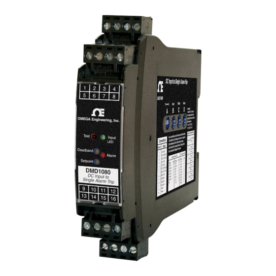
DMD1080
DMD1080-DC
DC Input Alarm Trips
M-5245/0818
Model
Module Power
DMD1080
85-265 VAC, 50/60 Hz or 60-300 VDC
DMD1080-DC
9-30 VDC or 10-32 VAC
Description
The DMD1080 accepts a DC voltage or current input and provide
visual alarm indication and alarm relay contact outputs. 15
voltage and 9 current input ranges can be field-configured via
external rotary and slide switches. Offset ranges such as 1-5
VDC and 4-20 mADC are also included.
Heavy-duty relay contacts allow the module to directly control
high capacity loads. Front-accessible potentiometers are used
to adjust the alarm setpoint from 0 to 100% and the deadband
from 1 to 100%.
The DMD1080 provides a single setpoint adjustment of the two
DPST relay contacts. The alarm output can be field configured
for HI or LO operation, latching or non-latching, and normal or
reverse acting. Deadband control can be adjusted from 1 to
100% and the alarm setpoint from 0 to 100%.
Sink/Source Input and Loop Supply
For maximum versatility, a current input can be selectively wired
for sinking or sourcing. This allows the DMD1080 to work with
powered or unpowered mA inputs. A regulated 15 VDC loop
excitation supply can be used to power passive input devices
eliminating the need for an additional DC loop supply.
Input and Alarm Status LEDs
The input LED varies in intensity with changes in the process
input signal. A red/green bi-color alarm status LED visually
indicate alarm status. These LEDs provide a quick visual status
of your process at all times.
Output Test / Unlatch
A functional test button can be used to verify the alarm and
system operation and also provides the additional function of
unlatching the alarm when the latching mode has been selected.
The output test button greatly aids in saving time during initial
startup and/or troubleshooting.
DC Input Ranges
24 field selectable ranges via switch settings
See chart on next page
Voltage:
0-50 mVDC to 0-10 VDC
Bipolar Voltage:
±5 VDC or ±10 VDC
Current:
0-1 mADC to 0-20 mADC, 4-20 mADC
Input Impedance and Burden
Voltage:
250 kΩ minimum
50 Ω typical
Current:
Voltage burden:
1 VDC at 20 mA current input
Isolation
Power to input isolation:
1200 V
Common mode protection:
600 VAC
p
Input Loop Power Supply
15 VDC ±10%, regulated, 25 mADC, max. ripple, <10 mV
May be selectively wired for sinking or sourcing mA input
LoopTracker
Variable brightness LED indicates input loop level and status
Relay Output
Single setpoint dual DPST contact sets, field configurable
2 Form A (NO) and 2 Form B (NC) contact sets (8 terminals)
May be field wired for Form C operation
Relay Contact Ratings
8 A @ 240 VAC resistive load
5 A @ 240 VAC inductive load (cos f = 0.4)
8 A @ 30 VDC resistive load
3.5 A @ 30 VDC inductive load (L/R = 7ms)
See diagram on other side
External contact protection such as an RC snubber is recom-
mended for inductive loads
or 600 VDC
RMS
0.5
0.3
0.1
Relay Contact Ratings
AC inductive load
AC resistive
(cos f = 0.4)
load
8
5
3
DC inductive load
1
(L/R = 7 ms)
DC resistive
load
0
3 5 10
30 50 100 300 500
Switching Voltage (V)
User's Guide
Shop online at
omega.com
e-mail: info@omega.com
For latest product manuals:
www.omegamanual.info
MADE IN
Lifetime
TM
Setpoint
12 turn potentiometer adjustable from 0 to 100% of span
Deadband
12 turn potentiometer adjustable from 1 to 100% of span
Output Test/Reset Button
Toggles relay to opposite state when pressed
Resets latching relay if latching relay mode is selected
Response Time
70 milliseconds typical
Ambient Temperature Range and Stability
–10°C to +60°C operating ambient
Better than 1% of span over operating temperature range
Better than 0.02% of span per °C
Power
85-265 VAC, 50/60 Hz or 60-300 VDC, 2 W maximum
D versions: 9-30 VDC or 10-32 VAC 50/60 Hz, 2 W maximum
Housing and Connectors
IP 40, requires installation in panel or enclosure
For use in Pollution Degree 2 Environment
Mount vertically to a 35 mm DIN rail
Four 4-terminal removable connectors, 14 AWG max wire size
WARNING: This product can expose you to chemicals includ-
ing nickel, which are known to the State of California to cause
cancer or birth defects or other reproductive harm. For more
information go to www.P65Warnings.ca.gov
Advertisement

Related Manuals for Omega DMD1080


Summary of Contents for Omega DMD1080
- Page 1 DMD1080-DC 9-30 VDC or 10-32 VAC Description The DMD1080 accepts a DC voltage or current input and provide visual alarm indication and alarm relay contact outputs. 15 voltage and 9 current input ranges can be field-configured via external rotary and slide switches. Offset ranges such as 1-5 VDC and 4-20 mADC are also included.
- Page 2 Typical of a system using Source installed. a passive transmitter and – a loop power supply to The DMD1080 operates two sets of relays in unison with a Alarm Configuration Settings power to the loop. single setpoint. Passive Alarm Type...
- Page 3 DMD1080, DMD1080-DC DC Input Alarm Trips Mounting to a DIN Rail Setup and Calibration Operation Install module vertically on a 35 mm DIN rail in a protective The input ranges are factory calibrated and do not require The green input LED provides a visual indication that a signal enclosure away from heat sources.
- Page 4 Department will issue an Authorized Return (AR) number immediately upon phone or written request. Upon examination by OMEGA, if the unit is found to be defective, it will be repaired or replaced at no charge. OMEGA’s WARRANTY does not apply to defects resulting from any action of the purchaser, including but not limited to mishandling, improper interfacing, operation outside of design limits, improper repair, or unauthorized modification.