Table of Contents
Advertisement
Quick Links
Advertisement
Table of Contents

Related Manuals for Omega OM-USB-TC-AI


Summary of Contents for Omega OM-USB-TC-AI
- Page 2 For Other Locations Visit omega.com/worldwide The information contained in this document is believed to be correct, but OMEGA accepts no liability for any errors it contains, and reserves the right to alter specifications without notice. WARNING: These products are not designed for use in, and should not be used for, human applications.
-
Page 3: Table Of Contents
Introducing the OM-USB-TC-AI......................5 Overview: OM-USB-TC-AI features ......................... 5 OM-USB-TC-AI block diagram ......................... 6 Software features ..............................6 Connecting a OM-USB-TC-AI to your computer is easy ................... 7 Chapter 2 Installing the OM-USB-TC-AI........................ 8 What comes with your OM-USB-TC-AI shipment? ..................8 Hardware .................................. - Page 4 OM-USB-TC-AI User's Guide Compatible sensors: T0x toT3x ............................18 Accuracy ................................19 Thermocouple measurement accuracy: T0x to T3x ......................19 Absolute accuracy: V0x-V3x ............................20 Settling time: V0x-V3x ..............................20 Analog input calibration ........................... 21 Throughput rate ..............................21 Digital I/O ................................. 21 Temperature alarms ............................22 Counter ................................
-
Page 5: Preface
Preface About this User’s Guide What you will learn from this user’s guide This user's guide describes the Omega Engineering OM-USB-TC-AI data acquisition devices and lists device specifications. Conventions in this user’s guide For more information about … Text presented in a box signifies additional information and helpful hints related to the subject matter you are reading. -
Page 6: Introducing The Om-Usb-Tc-Ai
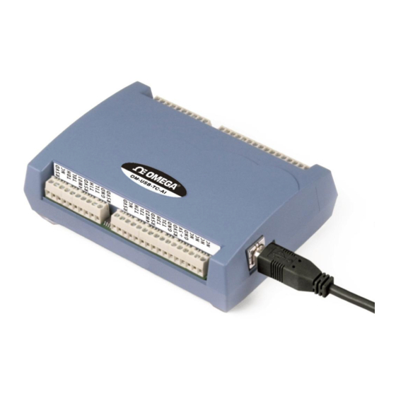
Introducing the OM-USB-TC-AI Overview: OM-USB-TC-AI features This user's guide contains all of the information you need to connect the OM-USB-TC-AI to your computer and to the signals you want to measure. The OM-USB-TC-AI is a USB 2.0 full-speed, thermocouple input module that is supported under popular ®... -
Page 7: Om-Usb-Tc-Ai Block Diagram
Figure 1. OM-USB-TC-AI functional block diagram Software features For information on the features of InstaCal and the other software included with your OM-USB-TC-AI, refer to the OMB-DAQ-2400, OM-USB, OM-WEB, and OM-WLS Series Data Acquisition Software User's Guide that shipped with your device. -
Page 8: Connecting A Om-Usb-Tc-Ai To Your Computer Is Easy
Microsoft HID because it is a standard, and its performance delivers full control and maximizes data transfer rates for your OM-USB-TC-AI. No third-party device driver is required. The OM-USB-TC-AI is plug-and-play. There are no jumpers to position, DIP switches to set, or interrupts to configure. ... -
Page 9: Installing The Om-Usb-Tc-Ai
As with any electronic device, you should take care while handling to avoid damage from static electricity. Before removing the OM-USB-TC-AI from its packaging, ground yourself using a wrist strap or by simply touching the computer chassis or other grounded object to eliminate any stored static charge. -
Page 10: Installing The Software
Installing the OM-USB-TC-AI To connect the OM-USB-TC-AI to your system, turn your computer on, and connect the USB cable to a USB port on your computer or to an external USB hub that is connected to your computer. The USB cable provides power and communication to the OM-USB-TC-AI. -
Page 11: Signal I/O Connections
Screw terminal pinout The OM-USB-TC-AI has four rows of screw terminals — two rows on the top edge of the housing, and two rows on the bottom edge. Each row has 26 connections. Between screw terminals 10 and 11 is the integrated CJC sensor used for thermocouple measurements. -
Page 12: Voltage Input Terminals (±V0H/V0L To ±V3H/V3L)
GND. A value of approximately 100 kΩ can be used for most applications. Caution! All ground pins on the OM-USB-TC-AI (pins 9, 19, 22, 27, 30, 33, 36, 39, 49) are common and are isolated from earth ground. If a connection is made to earth ground when using digital I/O and conductive thermocouples, the thermocouples are no longer isolated. -
Page 13: Ground Terminals (Gnd)
TTL level transitions from low to high. The counter can count events at frequencies of up to 1 MHz. Caution! All ground pins on the OM-USB-TC-AI (pins 9, 19, 22, 27, 30, 33, 36, 39, 49) are common and are isolated from earth ground. If a connection is made to earth ground when using digital I/O and conductive thermocouples, the thermocouples are no longer isolated. -
Page 14: Digital I/O Connections
Figure 4. Schematic showing switch detection by digital channel DIO0 All ground pins on the OM-USB-TC-AI (pins 9, 19, 22, 27, 30, 33, 36, 39, 49) are isolated from earth ground. If a connection is made to earth ground when using digital I/O and conductive thermocouples, the thermocouples are no longer isolated. -
Page 15: Configuring The Dio Channels To Generate Alarms
Signal I/O Connections Configuring the DIO channels to generate alarms The OM-USB-TC-AI features eight independent temperature alarms. All alarm options are software configurable. When a digital bit is configured as an alarm, that bit is configured as an output on the next power cycle and assumes the state defined by the alarm configuration. -
Page 16: Chapter 4 Functional Details
+2.5 V to the thermocouple’s low side at the C#L input. Always connect thermocouple sensors to the OM-USB-TC-AI in a floating fashion. Do not attempt to connect the thermocouple low side C#L to GND or to a ground referencing resistor. -
Page 17: Power
OM-USB-TC-AI User's Guide Functional Details Power The two terminals are isolated (500 VDC) from the USB +5V. Caution! Each +5V terminal is an output. Do not connect to an external power supply or you may damage the OM-USB-TC-AI and possibly the computer. -
Page 18: Chapter 5 Specifications
Chapter 5 Specifications Typical for 25 °C unless otherwise specified. All specifications apply to all temperature and voltage input channels unless otherwise specified. Specifications in italic text are guaranteed by design. Analog input Table 1. Generic analog input specifications Parameter Conditions Specification A/D converter type... -
Page 19: Channel Configurations
V0x to V3x Single-ended 4 single-ended channels Internally, the OM-USB-TC-AI has four, dual-channel, fully differential A/Ds providing a total of Note 1: eight input channels. Note 2: When connecting differential inputs to floating input sources, you must provide a DC return path from each differential input to ground. -
Page 20: Accuracy
These specs are for one year, or 3000 operating hours, whichever comes first, and for operation of the OM-USB-TC-AI between 15 °C and 35 °C. There is a CJC sensor on the temperature sensor input side of the module. The accuracy listed above assumes the screw terminals are at the same temperature as the CJC sensor. -
Page 21: Absolute Accuracy: V0X-V3X
1.69 17.98 Table 7 summarizes the noise performance for the OM-USB-TC-AI. Noise distribution is determined by gathering 1000 samples with inputs tied to ground at the user connector. Samples are gathered at the maximum specified sample rate of 2 S/s. -
Page 22: Analog Input Calibration
3.8 V min (IOH = -2.5 mA max) All ground pins on the OM-USB-TC-AI (pins 9, 19, 22, 27, 30, 33, 36, 39, 49) are common and Note 12: are isolated from earth ground. If a connection is made to earth ground when using digital I/O and conductive thermocouples, the thermocouples are no longer isolated. -
Page 23: Temperature Alarms
OM-USB-TC-AI User's Guide Specifications Temperature alarms Table 12. Temperature alarm specifications Parameter Specification Number of alarms 8 (one per digital I/O line) Alarm functionality Each alarm controls its associated digital I/O line as an alarm output. The input to each alarm may be any of the analog temperature input channels. -
Page 24: Microcontroller
(terminal block pin 21) Isolation Measurement system to PC 500 VDC min Note 14: This is the total current requirement for the OM-USB-TC-AI which includes up to 10 mA for the status LED. USB specifications Table 18. USB specifications Parameter... -
Page 25: Mechanical
OM-USB-TC-AI User's Guide Specifications Mechanical Table 20. Mechanical specifications Parameter Specification Dimensions (L × W × H) 128.52 x 88.39 × 35.56 mm (5.06 × 3.48 × 1.43 ft) User connection length 3 m (9.84 ft) max Screw terminal connector Table 21. - Page 26 Department will issue an Authorized Return (AR) number immediately upon phone or written request. Upon examination by OMEGA, if the unit is found to be defective, it will be repaired or replaced at no charge. OMEGA’s WARRANTY does not apply to defects resulting from any action of the purchaser, including but not limited to mishandling, improper interfacing, operation outside of design limits, improper repair, or unauthorized modification.
- Page 27 Where Do I Find Everything I Need for Process Measurement and Control? OMEGA…Of Course! Shop online at omega.com TEMPERATURE Thermocouple, RTD & Thermistor Probes, Connectors, Panels & Assemblies Wire: Thermocouple, RTD & Thermistor Calibrators & Ice Point References Recorders, Controllers & Process Monitors...