Table of Contents
Advertisement
Quick Links
Advertisement
Table of Contents

Related Manuals for Datavideo HDR-55

Summary of Contents for Datavideo HDR-55
- Page 1 HD/SD Recorder HDR-55 Quick Start Guide www.datavideo-tek.com...
-
Page 2: Table Of Contents
Table of contents Warnings and Precautions ..........................2 Warranty ................................3 Disposal................................3 Packing List..............................4 Introduction..............................4 Features................................4 How to Assemble 2.5" HDD in Removable Rack ..................5 Connections & Controls..........................6 Front Panel ..............................6 Rear Panel..............................7 Powering On.............................. -
Page 3: Warnings And Precautions
7. This product should only be operated from the type of power source indicated on the marking label of the AC adapter. If you are not sure of the type of power available, consult your Datavideo dealer or your local power company. -
Page 4: Warranty
Equipment that fails after the warranty period, has been operated or installed in a manner other than that specified by Datavideo, or has been subjected to abuse or modification, will be repaired for time and material charges at the Buyer’s expense. -
Page 5: Packing List
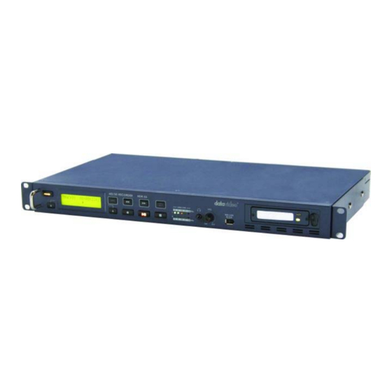
Instruction Manual Introduction The Datavideo HDR-55 is a hard drive based video recorder & player, with a removable hard drive enclosure. The HDR-55 records from standard and high definition video via SDI with a convenient loop through / pass through for monitoring. RS-422 & RS-232 remote control interface are standard. -
Page 6: How To Assemble 2.5" Hdd In Removable Rack
How to Assemble the 2.5” HDD in a Removable Rack 1. Remove the screws from the back cover of the enclosure and pull out the PCB board. NOTE: DO NOT REMOVE THE SCREWS ON THE FRONT COVER. 2. Place the 2.5” hard drive on the PCB board and slide the drive towards the rear SATA connectors on the board. -
Page 7: Connections & Controls
The HDR-55 has "auto Rewind and Playback" function. You just need to press "Rew" key first +"PLAY" key then the HDR-55 will replay the last segment just recorded (2G file size maximum). -
Page 8: Rear Panel
Rear Panel The GPI socket can be used for simple external control. The HDR-55 can accept pulse or level trigger inputs, which can trigger record or playback and pause commands See GPI Mode & Function Menus for more details. RS-422 Port. The HDR-55 can be controlled via RS-422 from external devices. -
Page 9: Powering On
Menu Options The HDR-55 is a menu driven unit; The menu settings are non-volatile (they are stored even when the unit is switched off), so many of the settings, such as date and time, you will only need to set once. We will look at each individual menu in more detail, but here is a quick overview of them. - Page 10 See GPI Mode & Function Menus for more details. SET DATE & TIME Sets the date and time on the HDR-55; the setting is non-volatile so it is stored when the unit is powered off. See Set Date & Time Menu for more details.
- Page 11 The 9 pin D-SUB can be set to either RS-422 (differential) or RS-232 (single end) transmission mode - Select RS-232 mode, you can control HDR-55 via RS-232 from PC. - Select RS-422 mode, you can control HDR-55 via RS-422 from external devices.
-
Page 12: Hdd Mode Menu
PC or MAC. The files appear in the root directory of the HDR-55 hard disk, and are numbered with the track number that appears in the LCD display when you are recording or playing back the track. -
Page 13: Hd Mpeg2 Bit Rate Menu
HD MPEG2 BIT RATE Menu To select the HD MPEG2 encoding BIT RATE: Press the Menu Button, to enter the menu mode Press the FWD (►►) Button to navigate the menus until HD MPEG2 BIT RATE is displayed Press the Next (▲) Button(right) to enter the HD MPEG2 BIT RATE menu Use the FWD(►►) or REW(◄◄) Button to select the desire bit rates (20,25,30,35,40,45,50,55,60) To confirm your selection and exit the menu press the Next (▲) Button(right). -
Page 14: Sd Mpeg2 Bit Rate Menu
SD MPEG2 BIT RATE Menu To select the SD MPEG2 encoding BIT RATE: Press the Menu Button, to enter the menu mode Press the FWD (►►) Button to navigate the menus until SD MPEG2 BIT RATE is displayed Press the Next (▲) Button(right) to enter the SD MPEG2 BIT RATE menu Use the FWD(►►) or REW(◄◄) Button to select the desire bit rates (5,10,15) To confirm your selection and exit the menu press the Next (▲) Button(right). -
Page 15: Set 1080I H-Res. Menu
SET 1080i H-RES. Menu Press the Menu Button, to enter the menu mode Press the FWD (►►) Button to navigate the menus until SET 1080i H-RES. is displayed. Press the Next (▲) Button(right) to enter the SET 1080i H-RES. menu Press the FWD (►►) Button to select either 1440 or 1920. -
Page 16: Gpi Mode & Functions Menus
GPI Mode & Functions Menus The HDR-55 can be set to receive either pulse or level GPI triggers, which can be set to activate Play / Pause or Rec / Pause. To select the GPI Mode: Press the Menu Button, to enter menu mode Press the FWD (►►) Button to navigate the menus until SET GPI TRIGGER MODE is displayed... -
Page 17: Set Date & Time Menu
Set Date & Time Menu To set the Date & Time on the HDR-55 Press the Menu Button, to enter menu mode Press the REW (◄◄) Button to navigate the menus until SET DATE & TIME is displayed Press the Next (▲) Button(right) to enter the SET Date & Time menu You will see a flashing cursor on the date value. -
Page 18: Format Hard Disk Menu
You will see ARE YOU SURE? displayed Press the Next (▲) Button(right)again to confirm that you want to format the hard disk. After a few seconds the HDR-55 will reboot and the display will return to normal Erase Track Menu Erase Track is used for deleting individual tracks from the HDR-55. -
Page 19: Hdd Surface Scan Menu
Press the Next (▲) Button(right) to exit the surface scan. A txt file called Result will have been created in the root directory of the HDR-55 HDD, this can be accessed via a PC, by connecting the HDR-55 as a HDD. -
Page 20: Playing A Track
(►II) Button. It is also possible to set the HDR-55 to loop play. In loop play the track will looped until stopped. To set up loop play press the Menu Button to enter menu mode and then the FWD (►►) Button until SETUP LOOP PLAY is displayed. -
Page 21: Recording A Track
The track you have selected on the HDR-55 is empty. The counter next to the TrackNo on the LCD display should b showing 00:00:00:00. There is some available space on the HDR-55 Hard Disk - Go to the FREE SPACE Menu and check that the HDR-55 is not full. -
Page 22: Connecting To A Computer
Connecting to a Computer Files that have been recorded onto the HDR-55 can be transferred directly to a PC or MAC via the IEEE- 1394 (iLink, FireWire) port. The files appear in the root directory of the HDR-55 hard disk, and are numbered with the track number that appears in the LCD display when you are recording or playing back the track. - Page 23 Folder to View Files. The drive should also appear in My Computer as an internal HDD. Once connected the HDR-55 can be used just like any HDD. You can select the required files and drag and drop them to the required destination.
-
Page 24: Connecting To A Mac
Press the Next (▲) Button(right) again to confirm, after a few seconds HDD Mode will be enabled The MAC should see the HDR-55 as a HDD and the files will appear in the root directory of the drive. You can select the required files and drag and drop them to the required destination. -
Page 25: Rs-422 Protocol Reference V1.0
RS-422 Protocol Reference V1.0 1. Interface Overview Conforming to EIA RS-422A. Full duplex communications channel is utilized. Data is transmitted asynchronously, bit serial, word serial with data exchange between devices. Standard transmission rate on the interface bus is 38400 bits per seconds (bps) The data word utilized by the interface system is as follows : PARITY START... - Page 26 2. Command Block Format The data communication is composed of the CMD-1/DATA COUNT byte, the CMD-2 byte, optional DATA bytes and the CHECKSUM byte. Commands are transmitted in order from the MSB (Most Significant Byte) to the LSB (Least Significant Byte). This means that when using the examples in this manual, the order in which the bytes are read is the same order in which they are transmitted.
- Page 27 3. Connector Pin Assignment Interface : 9 pin D-Sub female The RS-422 pin assignment of the Controller and HDR-45/55 is shown in the following table: Signal Controller HDR-45/55 Frame Ground Frame Ground Receive A(RX-) Transmit A(TX-) Transmit B(TX+) Receive B(RX+) Transmit Common Receive Common Spare...
- Page 28 4. Communication Protocol • All communications between the CONTROLLER and the DEVICE will be under the direct supervision of the CONTROLLER. When the DEVICE (HDR-45/55) receives the COMMAND from CONTROLLER, the following COMMAND is returned. ACK: In case that the DEVICE receives a COMMAND not requiring data COMMAND+DATA: In case that the DEVICE receives a COMMAND requiring data NAK+ERROR DATA:...
- Page 29 5. Command Table (without Checksum byte) Command Name Response Name 10h 01h Acknowledge (ACK) – command succeeded 12h 11h Device Return 11h 12h Negative Acknowledge (NAK) – command failed 00h 11h Device Type Request 12h 11h Device Type Response 20h 00h Stop 10h 01h 20h 01h...
- Page 30 6. Detailed Description of Commands 00h 11h : DEVICE TYPE REQUEST Send: 00h 11h 11h Return: 12h 11h B0h 12h E4h (HDR-45/55) 20h 00h : STOP Send: 20h 00h 20h Return: 10h 01h 11h 20h 01h : PLAY Send: 20h 01h 21h Return: 10h 01h 11h 20h 02h : RECORD Send: 20h 02h 22h...
- Page 31 Return: 10h 01h 11h 41h 61h NNh : SELECT AUDIO INPUT SOURCE NN = Audio Source, 0 = Analog audio, 1 = SDI Embedded Audio Send: 41h 61h 00h A2h (Analog audio input) Return: 10h 01h 11h Send: 41h 61h 01h A3h (SDI Embedded Audio) Return: 10h 01h 11h 41h 63h NNh : SELECT SD VIDEO ASPECT RATIO NN = Aspect Ratio, 2 = 4:3, 3 = 16:9, 0, 1 = Reserved...
- Page 32 7. Return Data 10h 01h : ACK When a command from the CONTROLLER is received normally, the DEVICE returns this command as acknowledgment. 11h 12h : NAK When a communication error is detected or an undefined COMMAND is received, the DEVICE returns this command as not- acknowledgment.
- Page 33 8. Status return data 7xh 20h : Bit 7 Bit 6 Bit 5 Bit 4 Bit 3 Bit 2 Bit 1 Bit 0 Hardware Data 0 Busy Disk Out Local Error Data 1 Standby On Stop Eject Rewind Fast Forward Record Play Still...
- Page 34 BIT-2 FAST FORWARD This bit will be set to 1 when the device goes into the FAST FORWARD mode. BIT-3 REWIND This bit will be set to 1 when the device goes into the FAST REWIND mode. BIT-4 EJECT This bit will be set to 1 when the device EJECTs hard disk. BIT-5 STOP This bit will be set to 1 when the device is in STOP mode.
- Page 35 Data-11 BIT-0 ~ 3 HUNDREDS OF TRACK NUMBER Hundreds of Track number in BCD BIT-4 ~ 7 0 Data-14 BIT-1 ENCODE SDI This bit will be set to 1 if the device is encoding SDI source. BIT-2 DECODE MPEG-2 This bit will be set to 1 if the device is decoding MPEG-2. BIT-4 ANALOGUE AUDIO This bit will be set to 1 if the audio input source is analogue.
-
Page 36: Dimension
Dimension... -
Page 37: Specifications
Specifications • 1x BNC connector for HD/SD-SDI input Inputs Interface • 2x XLR connector for audio input • 1x BNC connector for HD/SD-SDI pass through output • 1x BNC connector for SDI output Outputs Interface • 1x HDMI connector for HDMI output (1.1) •... -
Page 38: Service & Support
It is our goal to make your products ownership a satisfying experience. Our supporting staff is available to assist you in setting up and operating your system. Please refer to our web site www.datavideo-tek.com for answers to common questions, support requests or contact your local office below.