
Related Manuals for Delta Electronics IFD9506


Summary of Contents for Delta Electronics IFD9506
- Page 1 IFD9506 Ethernet Communication Module RS485 <--> Ethernet Operation Manual DVP-0224820-03...
-
Page 3: Table Of Contents
Switch off the power before wiring. IFD9506 is an OPEN TYPE device and therefore should be installed in an enclosure free of airborne dust, humidity, electric shock and vibration. The enclosure should prevent non-maintenance staff from operating the device (e.g. - Page 4 Ethernet Communication Module IFD9506 3.4 Explanation of Basic Registers (BR) ....................13 3.5 Modbus Exception Codes Supported ..................... 15 Monitoring Functions ........................16 4.1 Monitor Bit Registers (MB) ......................16 4.2 Monitor Word Registers (MW) ......................16 Setting Software ..........................18 5.1 Setting Communication &...
- Page 5 Ethernet Communication Module IFD9506 9.4.5 Account Management ......................48 9.5 Gateway Configuration ........................49 9.5.1 Serial Communication Setup ....................49 9.5.2 Serial Cache: Bit Monitor ......................49 9.5.3 Serial Cache: Word Monitor ....................50 9.5.4 Serial IP Table ........................50 9.6 Save Configuration .........................
-
Page 6: Introduction
To store 100 registers of data, the module should be used with firmware V1.62 or above and DCISoft V1.20 or above. 1.2 Installation and Wiring Connect the Ethernet port of IFD9506 to the Ethernet hub with the twisted pair cable CAT-5e. The mode setting for IFD9506 should be paid attention to. DVP-PLC Operation Manual... -
Page 7: Specifications
Ethernet Communication Module IFD9506 1.3 Specifications Network interface Interface RJ-45 with Auto MDI/MDIX Number of ports 1 port Transmission method IEEE802.3, IEEE802.3u Transmission cable Category 5e Transmission speed 10/100 Mbps Auto-Defect Communication protocol ICMP, IP, TCP, UDP, DHCP, SMTP, Modbus TCP, Ethernet/IP(Adapter) - Page 8 Ethernet Communication Module IFD9506 Terminal block (COM2) Interface Feed-through terminal 10PIN Transmission method RS-485 Transmission distance 1,200m 110, 150, 300, 600, 1200, 2400, 4800, 9600, 19200, 38400, 57600, 115200 Transmission speed Communication Modbus, User Define protocol Environment ESD (IEC 61131-2, IEC 61000-4-2): 8KV Air Discharge EFT (IEC 61131-2, IEC 61000-4-4): Power Line: ±2KV, Digital Input:...
-
Page 9: Product Profile & Outline
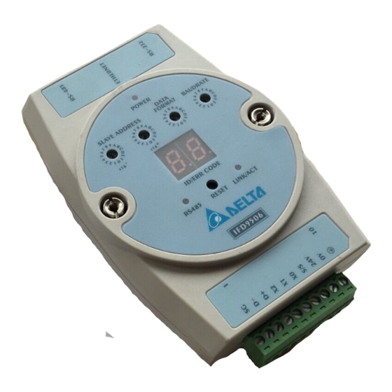
Ethernet Communication Module IFD9506 2 Product Profile & Outline 2.1 Dimension Unit: mm 2.2 Product Profiles Communication ports: RS-485, Ethernet, RS-232 RS-485 LED, Reset button, Ethernet LED POWER LED Module name RS-485 connector, digital input points, power ... - Page 10 0x00 via the address switch and reset the station address and data format via DCISoft or webpage. Check if there is any device with the same IP conflict IP as IFD9506 on the network or modify the IP address of IFD9506. DVP-PLC Operation Manual...
-
Page 11: Pin Definition
2.8 Node Address The node address setting here is the node address of IFD9506 itself. DO NOT duplicate it with the node address of the device connected to the RS-485 port. When IFD9506 is in normal operation, the node address will be displayed on the message display. -
Page 12: Data Format And Baud Rate
Ethernet Communication Module IFD9506 Switch setting Content When the node address is set to 0x00, the settings in the software are available after power on again. The firmware V2.06 and above supports the function. Valid Modbus communication address setting; 01…F6... -
Page 13: Feed-Through Terminal Pin Definition
Ethernet Communication Module IFD9506 2.10 Feed-through Terminal Pin Definition Signal Definition Reference ground of signal Data- Data- Digital input 2 Digital input 1 Digital input 0 Reference ground of digital input +24V input 0V input Earth ground DVP-PLC Operation Manual... -
Page 14: Modbus Communication
Write a single Coil 0x06 Write a single Register 0x0F Write multiple Coils 0x10 Write multiple registers 0x17 Read/Write multiple registers 3.2 Registers in IFD9506 and Modbus Addresses MODBUS address Function code Type Name Number (Hex) Discrete Input Digital input... -
Page 15: Explanation Of Basic Registers (Br)
The model code of IFD9506 is 0x0200. BR 1: Fi rmw a r e Ve rs i on Explanations: The firmware version of IFD9506 is displayed in hex, e.g. 0x0100 indicates version V1.00. BR 4: Com mun i cat ion Fo rm at Explanations:... - Page 16 Ethernet Communication Module IFD9506 BR4 High byte B6~B4 (138) 10001011 Enable Enable Serial Master Modbus (139) 10001100 Enable Enable Serial Slave Delta configuration ASCII (140) 10001101 Enable Enable Serial Slave Delta configuration (141) 10001110 Enable Enable Serial Slave Modbus ASCII (142)...
-
Page 17: Modbus Exception Codes Supported
Gateway destination device failed to respond For example, IFD9506 receives a message: “03 03 10 00 00 01”, but the equipment of node address 03 does not exist or does not make any response. IFD9506 will respond with “03 83 0b” which indicates there is no response in the target station after the timeout set by DCISoft is exceeded. -
Page 18: Monitoring Functions
Ethernet Communication Module IFD9506 4 Monitoring Functions The values in the device monitoring tables and monitored statuses can be read by monitor registers. The monitored-device tables are set in DCISoft. 4.1 Monitor Bit Registers (MB) Ethernet Communication Module: IFD9506 MB No. - Page 19 Ethernet Communication Module IFD9506 M W 251 ~ M W 35 0: M onit o re d Val u e Explanations: Every MW records the values in 1 register. MW251 MW252 MW253 MW254 MW255 MW256 MW257 MW258 MW259 MW260 Device 1 Device 2 Device 3 Device 4 Device 5 Device 6 Device 7 Device 8 Device 9 Device 10...
-
Page 20: Setting Software
This section gives instructions on how to set IFD9506 by DCISoft and explanations on each setup page. IFD9506 is set by UDP port 20006; therefore, you have to be aware of the relevant settings of the firewall. See the explanations below on the software. -
Page 21: Basic Settings
The basic settings include parameters such as module name, network settings and serial communication. 1. Module name: There can be many IFD9506 modules on the network. Thus, you can set a module name for each module to identify the module when you need to use them. - Page 22 IFD9506. To see if your setting is correct, conduct bitwise AND operations between your IP and subnet mask and destination IP and subnet mask. If the two values obtained are the same, the two IPs are in the same subnet. The default subnet mask of IFD9506 is 255.255.255.0.
-
Page 23: E-Mails Setting
E-Mail. When the E-Mail is triggered, IFD9506 will send the messages to the user by E-Mail. - Page 24 Provides bit-device addresses of serial slaves; able to read the content in the corresponding addresses of the designated slave. Station Address: Enter the slave address of the Modbus device to which IFD9506 connects. Modbus (Hex): Enter the absolute address of the slave in 4 hexadecimal digits. For example, the ...
-
Page 25: Serial Slave Mode
The monitoring function is available only for the connection through Ethernet port. When X appears in Present Value column, reading a serial salve failed by IFD9506. Check if the data format and baud rate settings are correct and the communication cable is connected properly. -
Page 26: Ip Filter
Ethernet Communication Module IFD9506 Device address: Address of the slave PLC, which is different from that of Gateway Relay IP address: IP address of the receiving terminal 5.6 IP Filter The IP filter is used for restricting the connection of the network in case some uncertain IP will cause errors. -
Page 27: Virtual Com Port
1. Listen Port/Destination Port: Range: 1024 ~ 65535. If IFD9506 works in serial master mode, you should set its own listening port number which is used by Ethernet client/master to make the connection. If IFD9506 works in serial slave mode, you should set the IP address of Ethernet service /slave and the destination port number which is open to make the connection. -
Page 28: Security Settings
6. Once the setup is successful, you can see the virtual COM you set in the Device Manager. 5.9 Security Settings To prevent the set values in IFD9506 from being modified, you can set passwords to lock the settings in IFD9506. -
Page 29: Returning To Factory Settings
Once the password is locked, all the pages cannot be set unless you unlock the password. If you have locked IFD9506 but forget the password, you can return IFD9506 to factory setting by RS-232 port, and all the settings will return to factory ones. - Page 30 10 seconds to return to default settings, so DO NOT switch off the power within the 10 seconds. Besides, you can also press “Reset” button for 2 seconds to return to default settings. Please power IFD9506 on again after returning to factory settings is done. ...
-
Page 31: Setting Operation Mode
The node address setting for IFD9506 must be different from any equipment of serial ports. And the data format and baud rate settings must keep the same as those of the equipment connected to the serial port RS-232 or RS-485. - Page 32 Therefore, the Modbus TCP instruction needs to correspond to the right node address of the equipment of the serial port. For example, if the station address of IFD9506 is 2 and the serial equipment is 3, IFD9506 may receive the following Modbus TCP instructions.
-
Page 33: Serial Slave Mode
6.3 Serial Slave Mode As a serial slave, IFD9506 is connected to the serial master by RS-232 or RS-485 port and is connected to the Ethernet server/ slave by Ethernet port. The communication instruction is sent by the serial master and is transferred to the Ethernet by IFD9506. And then IFD9506 will be waiting for the response from the Ethernet server/ slave, and eventually send the response back to the serial master. -
Page 34: User Define Mode
Ethernet Communication Module IFD9506 For example, if the station address of IFD9506 is 2, the IP address that station address 5 corresponds to in the Serial Slave Mode table is 192.168.1.58, as shown in the following figure: The following Modbus instructions are received in RTU mode. - Page 35 1. No condition is specified: if no condition box is checked, IFD9506 will make the judgement of the end of the packet based on the packet interval (1.5 characters of time). 2. Fix Length: after the box of Fix Length is checked, the start and stop items cannot be set. And IFD9506 DVP-PLC Operation Manual...
-
Page 36: Serial Device Server Mode (P2P Mode)
It supports the User Define communication protocol only, but does not support the settings on the User Define page. IFD9506 transfers all data received, which equals no condition is specified and makes the judgment of the packet end based on 1.5 characters of time. At the beginning of communication, the Ethernet equipment must first establish the connection to IFD9506, and then IFD9506 uses the connection to forward the data received from the serial port. - Page 37 If the switching speed of RS-485 slave is not fast enough, the data packets transmitted by IFD9506 may be lost or the slave may not receive full data.
-
Page 38: Ethernet/Ip Communication
(2) Explicit Message The Ethernet/ IP master can transmit the Modbus instruction to IFD9506 by placing it in an explicit message. Reading multiple devices and writing to a single device are supported. IFD9506 forwards the Modbus instruction to the serial slave and sends the response from the serial slave back to the Ethernet/ IP master. -
Page 39: Ethernet/Ip Operation Through Implicit Message
Set the parameters of IFD9506 with the rotary switches. Ensure that the data format and baud rate of IFD9506 are the same as those of the serial slave and the station address is different from that of the serial slave. - Page 40 Right click the red dot on the AS300 module icon and then select “Data Mapping” to open the data mapping table. The data register address mapping between IFD9506 and AS300 can be set in the data mapping table. DVP-PLC Operation Manual...
-
Page 41: Ethernet/Ip Operation Through Explicit Message
The device monitoring tables can be opened to verify the result in ISPSoft. The data in D2128 of AS300 should be the same as the data in the first device on the Word device monitoring table of IFD9506, and so on. - Page 42 Ethernet Communication Module IFD9506 See the programming example as below. DVP-PLC Operation Manual...
- Page 43 The Modbus instruction of 6 bytes: 01 03 00 00 00 0A is written into D500 ~ D502 in the example. After the EIPRW instruction is triggered by setting M100 to ON, the data are transmitted to IFD9506, then IFD9506 forwards the instruction data to the serial slave of station address 1 and meanwhile reads 10 registers of data.
-
Page 44: Network Security
IFD9605 with the firmware V2.06 or above supports the functions of diagnosis and setup through the webpage. 9.1 Webpage System Environment You can enter the IP address of IFD9506 on the webpage to connect to the device, obtain diagnostic data and conduct basic setup. -
Page 45: Information Display
After entering the page, log in to the default account "Admin" without any password. Set the password for "Admin" account after login. The webpage function of IFD9506 does not support user adding, user name change and login permission setup. After successful login, the user name is displayed in User field in read-only mode. -
Page 46: Diagnostic Information
Ethernet Link Up network port Modbus TCP and User Define TCP Information The number of connections to IFD9506 made by remote Number of connections (from client, max.= 16) TCP Client at present The total number of disconnections from remote TCP... -
Page 47: Protocol Diagnostic
Ethernet Communication Module IFD9506 Field Description The number of connections to remote TCP Server made Number of connections (to server, max.= 8) by IFD9506 at present Total number of failures of connection to remote TCP Count of disconnections (to server) - Page 48 The total number of Modbus TCP responses sent by the Ethernet total sent responses Ethernet terminal The number of Modbus TCP requests to IFD9506 itself sent Ethernet requests to IFD9506 (not forwarded) by the Ethernet master, which are not forwarded to the serial...
-
Page 49: Network Configuration
The number of timeouts judged by the Ethernet terminal 9.4 Network Configuration The equipment and network parameters of IFD9506 can be set here, and the parameters and functions are the same as those on DCISoft. For details, please refer to previous sections. After modifying parameters on the web page, you must press “Apply”... -
Page 50: Permitted Ip List
On this page, the user password can be modified. After modification is over, press “Apply” and save the setting on the Save page. If you forget the password, please start DCISoft to connect IFD9506 via RS-232 port, and restore IFD9506 to the factory settings. Then all setting values will return to the factory default values. -
Page 51: Gateway Configuration
Ethernet Communication Module IFD9506 9.5 Gateway Configuration The gateway-related functions of IFD9506 can be set here, and the parameters and functions are the same as those on DCISoft. For details, please refer to previous sections. After modifying any parameters on the web page, you must press “Apply”... -
Page 52: Serial Cache: Word Monitor
9.5.4 Serial IP Table You must set the page when IFD9506 works in serial slave mode. IFD9506 receives the requests received from the serial port and then sends them to the IP address specified in the table according to the Modbus station address in the instruction. -
Page 53: Save Configuration
Ethernet Communication Module IFD9506 9.6 Save Configuration After modification of setting values is made, you must press “Apply” and save the settings by click “Save” on this page. 9.7 System Setup 9.7.1 Firmware Update Click “Switch” to automatically switch to the engineering mode. DO NOT update the firmware by yourself. If you need update the firmware, please contact Delta factory or agent for confirmation and further operation. - Page 54 Ethernet Communication Module IFD9506 IFD9506 supports the webpage function. It can be set and monitored through the browser. IFD9506 is set up by UDP port 20006. Please be aware of the relevant settings for the firewall. The webpage settings are the same as those in DCISoft.
-
Page 55: Application Examples
(2) Set the IP of slave IFD9506 to “192.168.1.6”, station address to “7” and communication format to “38400, 8, E, 1, RTU”. (3) In the IFD9506 serial slave mode table, set the station addresses of the two devices to “1” and “3”, both of their relay IP addresses to “192.168.1.5”. - Page 56 Ethernet Communication Module IFD9506 Setting HMI editing software, Screen Editor: Step 1: Open Screen Editor, “File" “New”. In the “Base Port Controller” column, select “Delta Controller RTU”. Step 2: Click “Option” “Configuration”. Set up the communication format on “Communication” page. As below, set it to RS-485 communication mode.
- Page 57 Ethernet Communication Module IFD9506 Step 3: If you want to control the On/Off of Y0 (Y0 address: 0500) of the PLC at station address 0x0001 and On/Off of Y0 (Y0 address: 0500) of the PLC at station address 0x0003, select “Maintained”...
-
Page 58: Application Of Virtual Com Port
Screen and Recipe 10.2 Application of Virtual COM Port Through the virtual COM port, IFD9506 is able to transmit the data sent to RS-232 to the Ethernet by connecting to the software supporting serial ports, e.g. Delta’s WPLSoft, Application VFDSoft and ASDA-Soft. See the example below for how to connect IFD9506 to VFD-E AC motor drive through the virtual COM port by VFDSoft. - Page 59 Ethernet Communication Module IFD9506 Switch to “User Define” page and select “Listen Port”. Open Virtual COM setup page DVP-PLC Operation Manual...
- Page 60 Ethernet Communication Module IFD9506 Press “OK”, and you will see all the devices connected on the network. Select the module you need and press “OK”. Relevant information of the device will be imported automatically. Press “OK” to complete the setup.
- Page 61 Ethernet Communication Module IFD9506 Once the setup is successful, you can see the virtual COM you set in the Device Manger. Using Virtual COM in Delta VFDSoft Open Delta VFDSoft. DVP-PLC Operation Manual...
- Page 62 VFD-E (38400, 7, E, 1) and press “Test" button. Once the “Success” light is ON, the communication test is regarded successful. Press “OK”, and IFD9506 will be able to communicate with VFD-E by VFDSoft. DVP-PLC Operation Manual...
- Page 63 Ethernet Communication Module IFD9506 DVP-PLC Operation Manual...
- Page 64 Ethernet Communication Module IFD9506 MEMO DVP-PLC Operation Manual...