Table of Contents
Advertisement
Quick Links
Advertisement
Table of Contents

Related Manuals for Linksys 5G WiFi 6


Summary of Contents for Linksys 5G WiFi 6
- Page 1 Linksys FGW3000 User Guide...
-
Page 2: Table Of Contents
Table of Contents Table of Contents ..........................2 Introduction ............................4 Product Overview ......................4 LED Indicators ........................5 Installation ........................7 Web Interface ........................... 8 Login to Web-GUI ......................8 Detailed Configuration Page ..................10 Menu Structure ......................11 Mobile Network | PIN ...................... - Page 3 Management | Diagnostic Tools ..................47 About ............................48 Specification ........................... 49...
-
Page 4: Introduction
Introduction Product Overview Power Input Power on/off Switch LAN Port USB Port (Reserve) WPS Button Nano Sim Card Slot Reset Button (Press 5 sec for Reset to Default) -
Page 5: Led Indicators
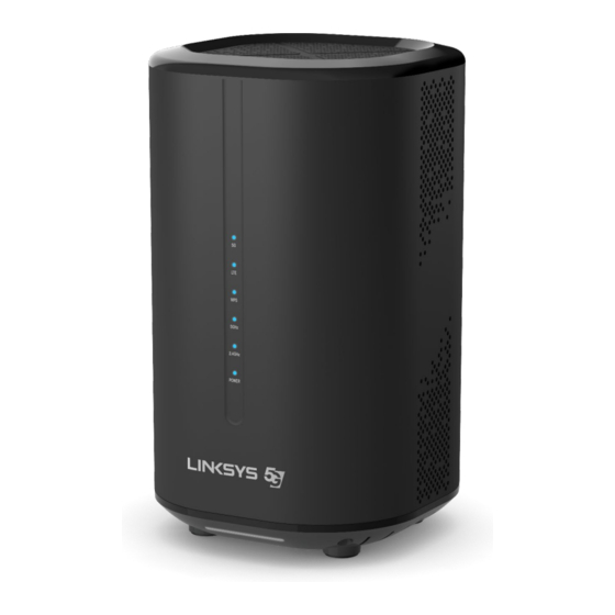
LED Indicators Icon Description Indication Status Power ON Power Power OFF 2.4GHz Wi-Fi ON WiFi Blinking Transmitting data 2.4GHz 2.4GHz Wi-Fi OFF 5GHz Wi-Fi ON WiFi Blinking Transmitting data 5GHz 5GHz Wi-Fi OFF Blinking WPS pairing (2min duration) WPS paired. (LED off after 5 sec) No WPS Blue LED Good Signal... -
Page 7: Installation
Installation Please follow the steps below to install the router: Step 1. Insert SIM card into the router with instructions shown below until it clicks. Step 2. Connect one of the LAN ports (any port will do) on the router to your PC with a RJ-45 Ethernet cable provided. -
Page 8: Web Interface
Web Interface Login to Web-GUI Users’ devices are assumed in CPE LAN side. Please follow the steps below to configure your device through the web interface: Step1: Open the Web browser (Ex: Internet Explorer, Firefox or Chrome) and enter the http://192.168.15.1 default IP address of CPE, which is : Web browser... - Page 9 Step3: After successful login, you can see “Brief Summary Page”. Brief Summary Page is composed of many blocks and each block contains its own feature. A concise description is presented in the block. Users can click on it to enter “Detailed Configuration Page”...
-
Page 10: Detailed Configuration Page
Detailed Configuration Page After clicking any block in “Brief Summary Page”, the webpage would be switched to the “Detailed Configuration Page”. (Take“Mobile Network” block for example) Detailed Configuration Main Menu Show the current main menu Sub Menu Clickable, can jump to another Sub Menu under the same Main Menu... -
Page 11: Menu Structure
Menu Structure After entering “Detailed Configuration Page”, the user can quickly jump to the specified Sub Menu. Users can refer to the menu structure given below: Mobile Network Status WiFi Settings Status WAN Setting Network LAN Setting Port Management Status IPv6 Settings Basic... -
Page 12: Mobile Network | Pin
Mobile Network | PIN Mobile Network>PIN Mobile Network >PIN >Enable PIN Mobile Network >PIN > Change PIN... - Page 13 Enable PIN: Enable/Disable PIN code protection.
- Page 14 Change PIN: Change the PIN code. Remaining Attempts: remaining times to try PIN code. Cancel button Reset fields to the last saved values. Commit the changes made and save to the CPE device, some Apply button services will be reloaded. Please make sure the current technology is 5G.
-
Page 15: Wifi
WiFi In WiFi main menu, you can display and configure settings about WiFi. Users can see SSID, current channel and working mode as well as configure wireless setting, security and access control list Display in Brief Summary Page Menu Structure: Status WiFi Settings... -
Page 16: Wifi | Status
WiFi | Status WiFi> Status State: Possible states are ON and OFF. ON: WiFi is on. OFF: WiFi is off. Radio Channel: The channel used by CPE. Working Mode: This sows the working mode you designate in WiFi->Setting. WiFi MAC: As titled. -
Page 17: Wifi | Settings | Wifi 2.4Ghz
WiFi | Settings | WiFi 2.4GHz WiFi> Settings>WiFi 2.4GHz Wireless Settings Interface Status: Click “Disable” button to disable WiFi, or click “Enable” to activate WiFi function. Network Name (SSID): SSID (service set identifier) is a label representing wireless AP. Wireless ... - Page 18 Security Security Types Setup: There are 10 different security types provided as below – Authentication Encryption Open Systems NONE 802.1x Settings - Rekey Interval 802.1x RADIUS Server RADIUS Port RADIUS Key Pre-shared Settings - WPA3-Personal CCMP Key Pass Phrase Pre-shared Settings - TKIP Rekey Interval...
- Page 19 802.1x Settings - TKIP Rekey Interval: WPA-Enterprise RADIUS Server TKIP/AES RADIUS Port RADIUS Key 802.1x Settings - TKIP Rekey Interval: WPA/WPA2-Enterprise RADIUS Server Mixed Mode TKIP/AES RADIUS Port RADIUS Key Wi-Fi Protected Setup(WPS) Enable WPS: User can share their WiFi via WPS when this box is checked. ...
-
Page 20: Wifi | Settings | Wifi 5Ghz
WiFi | Settings | WiFi 5GHz WiFi> Settings>WiFi 5GHz Wireless Setting Interface Status: Click “Disable” button to disable WiFi, or click “Enable” to activate WiFi function. Network Name (SSID): SSID (service set identifier) is a label representing wireless AP. Wireless ... - Page 21 Open Systems NONE 802.1x Settings - Rekey Interval 802.1x RADIUS Server RADIUS Port RADIUS Key Pre-shared Settings - WPA3-Personal CCMP Key Pass Phrase Pre-shared Settings - TKIP Rekey Interval WPA2-Personal TKIP/AES Key Pass Phrase Wi-Fi Protected Setup(WPS)– CCMP TKIP/CCMP Enable WPS Pre-shared Settings - TKIP Rekey Interval...
- Page 22 802.1x Settings - TKIP Rekey Interval: WPA/WPA2-Enterprise RADIUS Server Mixed Mode TKIP/AES RADIUS Port RADIUS Key Wi-Fi Protected Setup(WPS) Enable WPS: User can share their WiFi via WPS when this box is checked. Access Control List: Users can block or allow clients with certain MAC addresses to access to CPE. Disable: Any clients can establish the connection.
-
Page 23: Network
Network The “Network” page allows user to configure network function such as WAN setting, LAN Setting, QOS, Port Management, DSCP, and MGMT Service. Display in Brief Summary Page Menu Structure: Status WAN Setting Network LAN Setting Port Management... -
Page 24: Network | Status
Network | Status LAN Information Network> Status > LAN Information WAN Information: This section shows WAN IP, MAC, Gateway, DNS Server, Time Server of NR indoor CPE and statistics of TX and RX Bytes and Packets of WAN interface. Network > Status > WAN Information Lease Status Table: This section shows all clients who get IP from DHCP server in NR indoor CPE. -
Page 26: Network | Wan Setting (Nat Mode)
Network | WAN Setting (NAT Mode) Network > WAN Setting WAN Connection Type: NAT mode. WAN MTU: This value is “Maximum Transmission Unit”. The size of a single packet can only be as large as MTU. If the size of the packet exceeds MTU, the packet would be fragmented. DNS1/2: Domain Name Server, editable when users select “Static”... -
Page 27: Network | Lan Setting
Network | LAN Setting Network >LAN Setting LAN Setting: LAN IP Address / Subnet Mask: The IP address and subnet mask used by CPE in LAN If users choose other tunnel mode, this IP means LAN side domain and Web GUI IP address. ... - Page 28 through the Ethernet port or WiFi would obtain a dynamic IP address from CPE. Enable DHCP Server: enable/disable DHCP server DHCP Starting IP Address: The starting IP address assigned by DHCP server. DHCP Ending IP Address: The ending IP address assigned by DHCP server. Notice that WiFi and Ethernet share the same DHCP server, the range of IP addresses should not be narrow.
- Page 29 Network > DHCP Server> Lease Reservation Table “Example”, “11:22:33:44:55:66”, “192.168.15.179” are examples here. Cancel button Reset fields to the last saved values. Commit the changes made and save to the CPE device, some Apply button services will be reloaded.
-
Page 30: Network | Port Management
Network | Port Management Network > Port Management Port Forwarding: For a single port, multiple ports or a range of ports—sends traffic inbound on a specific port or ports to a specific device or port on your Wi-Fi Port Trigger: In port range triggering, the system watches outgoing data for specific port numbers. -
Page 31: Ipv6
IPv6 The “IPv6” page allows user to get IPv6 information such as WAN Connection Type and WAN IPv6 Address. Display in Brief Summary Page Menu structure: Status IPv6 Settings... -
Page 32: Ipv6 | Status
IPv6 | Status IPv6> Status IPv6 | Settings IPv6 Connection Type: Show IPv6 Connection Type with “Auto Configuration (SLAAC/DHCPv6). DNS From: Get DNS from Auto or Static LAN Prefix Type: choose LAN Prefix Type with Extend WAN Prefix, Prefix Delegation, or Static Auto IPv6 Address Assignment: auto assignment IPv6 address... -
Page 33: Firewall
Firewall The “Firewall” page allows user to configure firewall to block and grant some network access. Display in Brief Summary Page Menu structure: Basic Firewall Access Restriction... -
Page 34: Firewall | Basic
Firewall | Basic Firewall > Basic Enable Firewall: Enable/Disable firewall. DMZ IP Address: All network traffic from WAN is forwarded to this IP address in LAN. Redirect ICMP to the host: Thefunctionwill be activated if DMZ is enabled.Tick the checkbox to haveCPEpassICMPmessages to hosts, or un-tick the checkbox to let the CPE reply ICMP messages. -
Page 35: Firewall | Access Restriction
Firewall | Access Restriction Firewall > Access Restriction Set and enable individual firewall rules by date / Time, device and note blocked reason. -
Page 36: Management
Management The “Management” page allows user to configure the main system parameters such as password, language, device time/name …etc. Display in Brief Summary Page Menu structure: Account Device Setting Management Time Settings Restore Default Software Management | Account Management > Account The Account page lets you change the default username and password for superuser and enduser. - Page 37 Apply button Commit the changes made and save them to the CPE device. Cancel button Reset fields to the last saved values...
-
Page 38: Management | Device Setting
Management | Device Setting Management > Device Setting Timeout/Refresh Setting Management Session Timeout:Automatic logout after the period. (Range: 0-10 Minutes; 0 means never expired) GUI Refresh Time: When users press “auto” button in any page, the page refresh every the ... -
Page 39: Management | Time Settings
Management | Time Settings Management > Time Settings Current Local Time: Display current local time; or click “Synchronize with PC” button to synchronize the time of CPE with PC. Time Zone: as titled. Auto Adjust for Daylight Saving Time: Enable this option if your location observes Daylight ... -
Page 40: Management | Restore Default
Management | Restore Default Management > Restore Default Select Management>Restore Default to go back to the factory default settings. Restore Default: Click “Restore” button to clear all users’ configuration and restore to factory default settings. Restore to default settings Window Integrity Check: Integrity check for the software used in the device in case the storage device is broken. -
Page 41: Management | Software
Management | Software Management > Software Software Upgrade: Click “Browse” button to select the ipkg file to upload, and then click “Upgrade”to install the selected file. The Upgrading window will be shown as below and then the reboot process will be started to let the change taken effect. The ipkg file you have uploaded will be shown in the table below the device software version. - Page 42 Management > Software> FOTA Upgrade...
-
Page 43: Monitoring
Monitoring The “Monitoring” page allows user to monitor system resource such as CPU, Memory, Uplink and Downlik data rate, and enable Iperf and diagnostic tools …etc. Display in Brief Summary Page Menu structure: Status Monitoring Iperf Diagnostic Tools... -
Page 44: Management | Status
Management | Status The “Status” page allows user to monitor system resource such as CPU, Memory, Uplink and Downlik data rate. Management > Software>Status System Perf. Monitor Period: Set system perf. Monitor period by second Management > Software>CPU Utilization CPU Usage Threshold: Set CPU Usage Threshold percentage Management >... - Page 45 Management > Software>Uplink & Downlink Data Rate Management > Software>System Information...
-
Page 46: Management | Iperf
Management | Iperf Management > Iperf Enable/Disable Iperf with many parameters settings such as Iperf Version, Server Port, Management Port, Measurement Time, Protocol Type and get result... - Page 47 Management | Diagnostic Tools Management > Diagnostics Tools Use system Diagnostics tools to set up parameters such as Diagnostics Type, Protocol Type, Ping Count, Packet Size, Ping Timeout, and get the Diagnostic Result afterward...
- Page 48 About This section shows the device information such as Product Name, Serial Number, IMEI,and IMSI Display in Brief Summary Page Menu structure: About Status...
- Page 49 Specification Support 5G NR Sub 6GHz for both TDD & FDD 5G NR TDD Bands : 78/79* 5G NR FDD Bands : n1/3/5 Support LTE FDD Bands: B1/3/7/8 Support USIM card Web-based configuration ...