Table of Contents
Advertisement
Quick Links
www.ti.com
User's Guide
OPT3004DTSEVM User's Guide
This user's guide describes the characteristics, operation, and use of the OPT3004DTSEVM evaluation module.
It discusses how to set up and configure the software and hardware, and reviews various aspects of the program
operation. Throughout this document, the terms evaluation board, evaluation module, and EVM are synonymous
with the OPT3004DTSEVM. This document also includes an electrical schematic, printed circuit board (PCB)
layout drawings, and a parts list for the EVM.
SBOU274 – DECEMBER 2021
Submit Document Feedback
ABSTRACT
Copyright © 2021 Texas Instruments Incorporated
OPT3004DTSEVM User's Guide
1
Advertisement
Table of Contents

Related Manuals for Texas Instruments OPT3004DTSEVM


Summary of Contents for Texas Instruments OPT3004DTSEVM
- Page 1 OPT3004DTSEVM User's Guide ABSTRACT This user’s guide describes the characteristics, operation, and use of the OPT3004DTSEVM evaluation module. It discusses how to set up and configure the software and hardware, and reviews various aspects of the program operation. Throughout this document, the terms evaluation board, evaluation module, and EVM are synonymous with the OPT3004DTSEVM.
-
Page 2: Table Of Contents
Table of Contents www.ti.com Table of Contents Trademarks....................................3 Overview....................................4 2.1 OPT3004DTSEVM Kit Contents............................2.2 Related Documentation from Texas Instruments....................... 3 OPT3004DTSEVM Hardware..............................3.1 Theory of Operation for the OPT3004DTSEVM.........................7 3.2 OPT3004DTSEVM Hardware Overview..........................4 OPT3004DTSEVM Software..............................4.1 Hardware Requirements..............................4.2 Software Installation................................8... -
Page 3: Trademarks
Figure 4-7. OPT3004DTSEVM Software-Installation Prompts....................Figure 4-8. OPT3004DTSEVM Software-Installation Prompts....................Figure 4-9. Typical Hardware Connection..........................Figure 4-10. Typical Response After Connecting OPT3004DTSEVM to the Computer............Figure 4-11. OPT3004 Main Operation Screen......................... Figure 4-12. Hardware Error Message............................Figure 4-13. GUI Capture Running............................15... -
Page 4: Overview
(ALS) with a digital output integrated circuit. It uses a two-wire interface that works with the I C protocol making it ideal for many applications. The OPT3004DTSEVM is a platform for evaluating the performance of the OPT3004 under various conditions. The OPT3004DTSEVM consists of two PCBs. -
Page 5: Related Documentation From Texas Instruments
The following documents provide information regarding Texas Instruments' integrated circuits used in the assembly of the OPT3004DTSEVM. This user's guide is available from the TI web site under literature number SBOU274. Any letter appended to the literature number corresponds to the document revision that is current at the time of the writing of this document. -
Page 6: Opt3004Dtsevm Hardware
3 OPT3004DTSEVM Hardware Figure 3-1 shows the system setup for the OPT3004DTSEVM. The computer runs the graphical user interface (GUI) software that communicates with the OPTMBEVM board over a USB connection. The OPTMBEVM has a USB Type C port and ships with a USB-C to USB-A cable. The OPTMBEVM board acts as a bridge between the software running on the PC and the OPT3004DTS coupon board. -
Page 7: Theory Of Operation For The Opt3004Dtsevm
The EVM ships with the coupon plugged into the motherboard. If not already assembled, the basic hardware setup for the OPT3004DTSEVM involves plugging the coupon board into the motherboard socket. Take special care to make sure the coupon is oriented correctly as shown in Figure 2-1. -
Page 8: Opt3004Dtsevm Software
The OPT3004DTSEVM software is available through the OPT3004DTSEVM Product Folder on the TI web site (www.ti.com). To install the software to your computer, navigate to the OPT3004DTSEVM software, and open the installer directory. Launch the OPT3004DTSEVM installation file, OPT3004DTS_EVM_Latte.exe, as shown in the figure below. -
Page 9: Figure 4-2. Opt3004Dtsevm Software-Installation
OPT3004DTSEVM Software The OPT3004EVM software then begins the installation process, as shown in Figure 4-2. Figure 4-2. OPT3004DTSEVM Software-Installation Launch Follow the prompts as shown in Figure 4-3 Figure 4-8 to install the OPT3004DTSEVM software. Figure 4-3. OPT3004DTSEVM Software-Installation Prompts SBOU274 –... -
Page 10: Figure 4-4. Opt3004Dtsevm Software-Installation Prompts
OPT3004DTSEVM Software www.ti.com Figure 4-4. OPT3004DTSEVM Software-Installation Prompts Figure 4-5. OPT3004DTSEVM Software-Installation Prompts OPT3004DTSEVM User's Guide SBOU274 – DECEMBER 2021 Submit Document Feedback Copyright © 2021 Texas Instruments Incorporated... -
Page 11: Figure 4-6. Opt3004Dtsevm Software-Installation Prompts
OPT3004DTSEVM Software Figure 4-6. OPT3004DTSEVM Software-Installation Prompts Figure 4-7. OPT3004DTSEVM Software-Installation Prompts SBOU274 – DECEMBER 2021 OPT3004DTSEVM User's Guide Submit Document Feedback Copyright © 2021 Texas Instruments Incorporated... -
Page 12: Typical Opt3004Dtsevm Hardware Setup
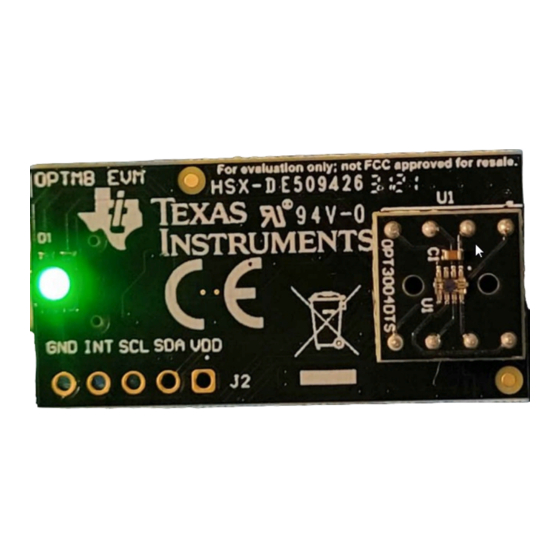
OPT3004DTSEVM Software www.ti.com Figure 4-8. OPT3004DTSEVM Software-Installation Prompts The OPT3004EVM GUI software is now installed. 4.3 Typical OPT3004DTSEVM Hardware Setup Plug the male USB-C cable to the OPTMBEVM board and then plug the male USB-A cable into the computer. The green light will light up on the EVM as shown in the figure below. -
Page 13: Figure 4-9. Typical Hardware Connection
Figure 4-10. Typical Response After Connecting OPT3004DTSEVM to the Computer Connect the EVM via USB to the PC. If Windows shows a notification that a driver is not found for the device connected, see the instructions to manually install drivers in Section 6.1... -
Page 14: Launching The Opt3004Evm Software
OPT3004DTSEVM Software www.ti.com 4.4 Launching the OPT3004EVM Software With the OPT3004DTSEVM properly connected, launch the Latte EVM GUI software from the Windows Start menu. The software launches with a screen similar to that shown in Figure 4-11. Figure 4-11. OPT3004 Main Operation Screen... -
Page 15: Opt3004Evm Software Operation
This section primarily discusses how to operate the OPT3004EVM software. The GUI has a primary window that is used to configure and read from the OPT3004DTSEVM, along with two other windows that are used to access different features of the OPT3004DTSEVM. Basic GUI functionality and a description of the tabs are also presented in this section. - Page 16 When Latte is launched the GUI window appears front and center. However, there is a second window that is minimized at launch. This is the scripts window and exposes some more advanced features of the Latte platform that will be described below. OPT3004DTSEVM User's Guide SBOU274 – DECEMBER 2021 Submit Document Feedback Copyright © 2021 Texas Instruments Incorporated...
-
Page 17: Figure 4-14. Latte Scripts Window
OPT3004DTSEVM Software SBOU274 – DECEMBER 2021 OPT3004DTSEVM User's Guide Submit Document Feedback Copyright © 2021 Texas Instruments Incorporated... -
Page 18: Figure 4-15. Registers View
Registers x02 and x03 enforce low and high limits, respectively, on the output ranges (exponent) and values (mantissa) from the OPT3004. These registers are not included in the register view. Additional Features of the Scripts Window Hidden IDE Window OPT3004DTSEVM User's Guide SBOU274 – DECEMBER 2021 Submit Document Feedback Copyright © 2021 Texas Instruments Incorporated... - Page 19 Open the devInit.py script by clicking on the corresponding file in the OPT3004DTSEVM folder on the left side of the screen. This displays the contents of the script on the center of the window. With devInit.py still selected in TI-Latte, click Run>Buffer from the top menu bar of TI-Latte (or press F5) to run the script.
-
Page 20: Schematic, Pcb Layout, And Bill Of Materials
Figure 5-1 shows the schematic of the OPT3004DTS coupon board. C1 is a bypass capacitor for device VDD. Figure 5-1. OPT3004 Coupon Board Schematic OPT3004DTSEVM User's Guide SBOU274 – DECEMBER 2021 Submit Document Feedback Copyright © 2021 Texas Instruments Incorporated... -
Page 21: Figure 5-2. Pcb Top Layer
Figure 5-5 show the assembly drawings of the top and bottom PCB layers, respectively. Figure 5-2. PCB Top Layer Figure 5-3. PCB Bottom Layer SBOU274 – DECEMBER 2021 OPT3004DTSEVM User's Guide Submit Document Feedback Copyright © 2021 Texas Instruments Incorporated... -
Page 22: Figure 5-4. Pcb Top-Layer Assembly Drawing
Figure 5-4. PCB Top-Layer Assembly Drawing Figure 5-5. PCB Bottom-Layer Assembly Drawing 5.1.3 Bill of Materials Table 5-1 lists the bill of materials for the OPT3004DTS coupon board. OPT3004DTSEVM User's Guide SBOU274 – DECEMBER 2021 Submit Document Feedback Copyright © 2021 Texas Instruments Incorporated... -
Page 23: Motherboard
Alternatively, a header can be populated at J2 for easier access. Figure 5-6. OPTMBEVM Schematic SBOU274 – DECEMBER 2021 OPT3004DTSEVM User's Guide Submit Document Feedback Copyright © 2021 Texas Instruments Incorporated... -
Page 24: Figure 5-7. Pcb Top Layer
Figure 5-5 show the assembly drawings of the top and bottom PCB layers, respectively. Figure 5-7. PCB Top Layer Figure 5-8. PCB Bottom Layer OPT3004DTSEVM User's Guide SBOU274 – DECEMBER 2021 Submit Document Feedback Copyright © 2021 Texas Instruments Incorporated... -
Page 25: Figure 5-9. Pcb Top-Layer Assembly Drawing
Table 5-2. OPTMBEVM Bill of Materials Designator Quantity Description PartNumber Manufacturer CAP, CERM, 1 uF, 10 V, GCM155C71A105KE38D MuRata +/- 10%, X7S, AEC-Q200 Grade 1, 0402 SBOU274 – DECEMBER 2021 OPT3004DTSEVM User's Guide Submit Document Feedback Copyright © 2021 Texas Instruments Incorporated... - Page 26 Header, 2.54mm, 5x1, 61300511121 Wurth Elektronik Gold, TH RES, 0, 5%, .05 W, AEC- ERJ-1GN0R00C Panasonic Q200 Grade 0, 0201 OPT3004DTSEVM User's Guide SBOU274 – DECEMBER 2021 Submit Document Feedback Copyright © 2021 Texas Instruments Incorporated...
-
Page 27: Troubleshooting
Figure 6-1, use the following steps. If two USB Serial Device devices show up as COM ports automatically (as is the case with Windows 10), then this section can be skipped. Figure 6-1. OPT3004DTSEVM on Microsoft ® Windows ®... - Page 28 Troubleshooting www.ti.com 4. Click Browse my computer for driver software 5. Click Let me pick from a list of device drivers on my computer. OPT3004DTSEVM User's Guide SBOU274 – DECEMBER 2021 Submit Document Feedback Copyright © 2021 Texas Instruments Incorporated...
- Page 29 Troubleshooting 6. Select Show All Devices and click the Next button. 7. Click the Have Disk… button. SBOU274 – DECEMBER 2021 OPT3004DTSEVM User's Guide Submit Document Feedback Copyright © 2021 Texas Instruments Incorporated...
- Page 30 Troubleshooting www.ti.com 8. Click the Browse… button. 9. Navigate to “C:\Users\<username>\Documents\Texas Instruments\Latte\projects\OPT3004\drivers” and choose MSP430_CDC. Click the Open button. 10. Click the OK button OPT3004DTSEVM User's Guide SBOU274 – DECEMBER 2021 Submit Document Feedback Copyright © 2021 Texas Instruments Incorporated...
- Page 31 11. Select the first USB serial device and click the Next button. 12. Click the Yes button. 13. The driver should now install properly. SBOU274 – DECEMBER 2021 OPT3004DTSEVM User's Guide Submit Document Feedback Copyright © 2021 Texas Instruments Incorporated...
- Page 32 USB Serial Device when installing the driver as the following figure shows. 15. When the driver is installed, you will see the following message. OPT3004DTSEVM User's Guide SBOU274 – DECEMBER 2021 Submit Document Feedback Copyright © 2021 Texas Instruments Incorporated...
- Page 33 16. The two USB Serial Device devices should now appear in the device manager under Ports (COM & LPT) as the following image shows. SBOU274 – DECEMBER 2021 OPT3004DTSEVM User's Guide Submit Document Feedback Copyright © 2021 Texas Instruments Incorporated...
- Page 34 STANDARD TERMS FOR EVALUATION MODULES Delivery: TI delivers TI evaluation boards, kits, or modules, including any accompanying demonstration software, components, and/or documentation which may be provided together or separately (collectively, an “EVM” or “EVMs”) to the User (“User”) in accordance with the terms set forth herein.
- Page 35 www.ti.com Regulatory Notices: 3.1 United States 3.1.1 Notice applicable to EVMs not FCC-Approved: FCC NOTICE: This kit is designed to allow product developers to evaluate electronic components, circuitry, or software associated with the kit to determine whether to incorporate such items in a finished product and software developers to write software applications for use with the end product.
- Page 36 www.ti.com Concernant les EVMs avec antennes détachables Conformément à la réglementation d'Industrie Canada, le présent émetteur radio peut fonctionner avec une antenne d'un type et d'un gain maximal (ou inférieur) approuvé pour l'émetteur par Industrie Canada. Dans le but de réduire les risques de brouillage radioélectrique à...
- Page 37 www.ti.com EVM Use Restrictions and Warnings: 4.1 EVMS ARE NOT FOR USE IN FUNCTIONAL SAFETY AND/OR SAFETY CRITICAL EVALUATIONS, INCLUDING BUT NOT LIMITED TO EVALUATIONS OF LIFE SUPPORT APPLICATIONS. 4.2 User must read and apply the user guide and other available documentation provided by TI regarding the EVM prior to handling or using the EVM, including without limitation any warning or restriction notices.
- Page 38 Notwithstanding the foregoing, any judgment may be enforced in any United States or foreign court, and TI may seek injunctive relief in any United States or foreign court. Mailing Address: Texas Instruments, Post Office Box 655303, Dallas, Texas 75265 Copyright © 2019, Texas Instruments Incorporated...
- Page 39 TI products. TI’s provision of these resources does not expand or otherwise alter TI’s applicable warranties or warranty disclaimers for TI products. TI objects to and rejects any additional or different terms you may have proposed. IMPORTANT NOTICE Mailing Address: Texas Instruments, Post Office Box 655303, Dallas, Texas 75265 Copyright © 2021, Texas Instruments Incorporated...