Table of Contents
Advertisement
This equipment has been tested and found to comply with the limits of a Class B digital device,
pursuant to Part 15 of the FCC Rules. These limits are designed to provide reasonable protection
against harmful interference in a residential installation. This equipment generates, uses, and can
radiate radio frequency energy and, if not installed and used in accordance with the instructions,
may cause harmful interference to radio communications. There is no guarantee that interference
will not occur in a particular installation.
The vendor makes no representations or warranties with respect to the contents here and
specially disclaims any implied warranties of merchantability or fitness for any purpose. Further
the vendor reserves the right to revise this publication and to make changes to the contents here
without obligation to notify any party beforehand.
Duplication of this publication, in part or in whole, is not allowed without first obtaining the
vendor's approval in writing.
The content of this user's manual is subject to be changed without notice and we will not be
responsible for any mistakes found in this user's manual. All the brand and product names are
trademarks of their respective companies.
FCC Information and Copyright
Dichiarazione di conformità sintetica
Ai sensi dell'art. 2 comma 3 del D.M. 275 del
30/10/2002
Si dichiara che questo prodotto è conforme
alle normative vigenti e soddisfa i requisiti
essenziali richiesti dalle direttive
2004/108/CE, 2006/95/CE e 1999/05/CE
quando ad esso applicabili
Short Declaration of conformity
We declare this product is complying with the
laws in force and meeting all the essential
requirements as specified by the directives
2004/108/CE, 2006/95/CE and 1999/05/CE
whenever these laws may be applied
Advertisement
Chapters
Table of Contents

Related Manuals for Biostar TB360-BTC PRO 2.0


Summary of Contents for Biostar TB360-BTC PRO 2.0
-
Page 1: Fcc Information And Copyright
FCC Information and Copyright This equipment has been tested and found to comply with the limits of a Class B digital device, pursuant to Part 15 of the FCC Rules. These limits are designed to provide reasonable protection against harmful interference in a residential installation. This equipment generates, uses, and can radiate radio frequency energy and, if not installed and used in accordance with the instructions, may cause harmful interference to radio communications. -
Page 2: Table Of Contents
Table Of Contents FCC Information and Copyright ������������������������������������������������������������������������������� 1 Chapter 1: Introduction ������������������������������������������������������������������������������������������� 3 1.1 Before You Start ........................3 1.2 Package Checklist ........................ 3 1.3 Specifications ........................4 1.4 Rear Panel Connectors ......................5 1.5 Motherboard Layout ......................6 Chapter 2: Hardware Installation �����������������������������������������������������������������������������... -
Page 3: Chapter 1: Introduction
TB360-BTC PRO 2.0 Chapter 1: Introduction 1�1 Before You Start Thank you for choosing our product. Before you start installing the motherboard, please make sure you follow the instructions below: • Prepare a dry and stable working environment with sufficient lighting. -
Page 4: Specifications
1x COM Serial Header 1x Clear CMOS Header Form Factor ATX Form Factor, 295mm x 210mm Windows 10(64bit) OS Support * Biostar reserves the right to add or remove support for any OS with or without notice. 4 | Chapter 1: Introduction... -
Page 5: Rear Panel Connectors
TB360-BTC PRO 2.0 1.4 Rear Panel Connectors Note » VGA / HDMI port only works with an Intel® integrated Graphics Processor. » Maximum resolution VGA: 1920 x 1200 @60Hz HDMI: 4096 x 2160 @24Hz, compliant with HDMI 1.4 » When using the front HD audio jack and plug in the headset, the rear sound will be automatically Disabled. » To configure 7.1-channel audio, you have to use a chassis with HD front panel audio module and enable the multi-channel audio feature through O.S. Audio Utility. » The mainboard supports two onboard display outputs at same time and the display output configuration can be selected in Intel graphics driver utility. The 2/ 4/ 5.1/ 7.1-channel configuration Audio Port 2-channel 4-channel 5.1 channel 7.1 channel... -
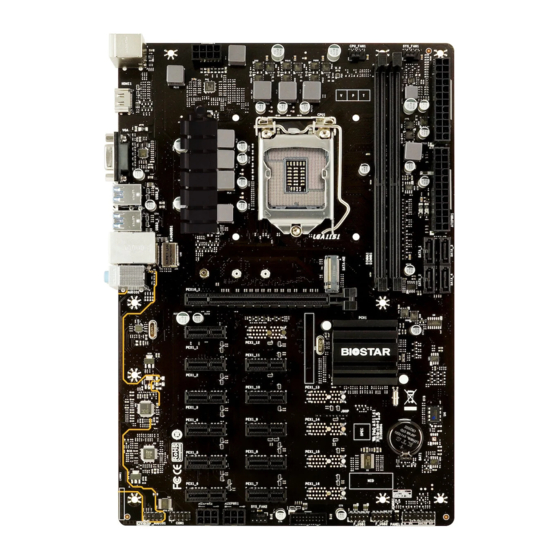
Page 6: Motherboard Layout
1.5 Motherboard Layout Note » represents the 1st pin. 6 | Chapter 1: Introduction... -
Page 7: Chapter 2: Hardware Installation
TB360-BTC PRO 2.0 Chapter 2: Hardware Installation 2.1 Install Central Processing Unit (CPU) Step 1: Locate the CPU socket on the motherboard Note » Remove pin cap before installation, and make good preservation for future use. When the CPU is removed, cover the pin cap on the empty socket to ensure pin legs won’t be damaged. » The motherboard might equip with two different types of pin cap. Please refer below instruction to remove the pin cap. Step 2: Pull the socket locking lever out from the socket and then raise the lever up. - Page 8 Step 4: Hold processor with your thumb and index fingers, oriented as shown. Align the notches with the socket. Lower the processor straight down without tilting or sliding the processor in the socket. Step 5: Hold the CPU down firmly, and then lower the lever to locked position to complete the installation.
-
Page 9: Install A Heatsink
TB360-BTC PRO 2.0 2.2 Install a Heatsink Step 1: Place the CPU fan assembly on top of the installed CPU and make sure that the four fasteners match the motherboard holes. Orient the assembly and make the fan cable is closest to the CPU fan connector. -
Page 10: Connect Cooling Fans
2.3 Connect Cooling Fans These fan headers support cooling-fans built in the computer. The fan cable and connector may be different according to the fan manufacturer. CPU_FAN1: CPU Fan Header Pin Assignment Ground +12V FAN RPM rate sense Smart Fan Control (By Fan) SYS_FAN1/ SYS_FAN2: System Fan Header Pin Assignment Ground... - Page 11 TB360-BTC PRO 2.0 Step 1: Unlock a DIMM slot by pressing the retaining clips outward. Align a DIMM on the slot such that the notch on the DIMM matches the break on the slot. Step 2: Insert the DIMM vertically and firmly into the slot until the retaining clips snap back in place and the DIMM is properly seated.
-
Page 12: Expansion Slots
2.5 Expansion Slots PEX16_1: PCI-Express Gen3 x16 Slot • PCI-Express 3.0 compliant. • Theoretical maximum bandwidth using two slots simultaneously is 16GB/s for each slot, a total of 32GB/s. PEX1_1/ PEX1_2/ PEX1_3/ PEX1_4/ PEX1_5/ PEX1_6/ PEX1_7/ PEX1_8/ PEX1_9/ PEX1_10/ PEX1_11: PCI-Express Gen3 x1 Slots • ... -
Page 13: Jumper & Switch Setting
TB360-BTC PRO 2.0 2.6 Jumper & Switch Setting The illustration shows how to set up jumpers. When the jumper cap is placed on pins, the jumper is “close”, if not, that means the jumper is “open”. Pin opened Pin closed... -
Page 14: Headers & Connectors
2.7 Headers & Connectors ATXPWR1/ ATXPWR2: ATX Power Source Connector For better compatibility, we recommend to use a standard ATX 24-pin power supply for this connector. Make sure to find the correct orientation before plugging the connector. Assignment Assignment +3.3V +3.3V -12V +3.3V... - Page 15 TB360-BTC PRO 2.0 Install Two Power Supply Rule: You can install your two power supply by following steps: The 24-pins ATX power connector of power supply1 is connected to ATXPWR1. The 8-pins or 4-pins ATX power connector of power supply1 is connected to ATXPWR3.
- Page 16 PANEL1: Front Panel Header This 16-pin header includes Power-on, Reset, HDD LED, Power LED, and speaker connection. Pin Assignment Function Pin Assignment Function Speaker 10 N/A Connector 11 N/A Speaker 12 Power LED (+) Power HDD LED (+) Hard drive 13 Power LED (+) HDD LED (-) 14 Power LED (-)
- Page 17 TB360-BTC PRO 2.0 F_USB1/ F_USB2: Header for USB 2.0 Ports at Front Panel This header allows user to add additional USB ports on the PC front panel, and also can be connected with a wide range of external peripherals. Assignment...
-
Page 18: Chapter 3: Uefi Bios & Software
The BIOS can be updated using either of the following utilities: • BIOSTAR BIOS-FLASHER: Using this utility, the BIOS can be updated from a file on a hard disk, a USB drive (a flash drive or a USB hard drive), or a CD-ROM. - Page 19 TB360-BTC PRO 2.0 6. Select the proper BIOS file, and a message asking if you are sure to flash the BIOS file. Click “Yes” to start updating BIOS. 7. A dialog pops out after BIOS flash is completed, asking you to restart the system. Press the <Y> key to restart system.
- Page 20 Then, the BIOS Update is completed. BIOS Update Utility (through a BIOS file) 1. Installing BIOS Update Utility from the DVD Driver. 2. Download the proper BIOS from http://www.biostar.com.tw/ 3. Launch BIOS Update Utility and click the “Update BIOS” button on the main screen.
- Page 21 TB360-BTC PRO 2.0 5. Choose the location for your BIOS file in the system. Please select the proper BIOS file, and then click on “Open”. It will take several minutes, please be patient. 6. After the BIOS Update process is finished, click on “OK”...
-
Page 22: Software
3.3 Software Installing Software Insert the Setup DVD to the optical drive. The driver installation program would appear if the Auto-run function has been enabled. Select Software Installation, and then click on the respective software title. Follow the on-screen instructions to complete the installation. Launching Software After the installation process is completed, you will see the software icon showing on the desktop. -
Page 23: Chapter 4: Useful Help
TB360-BTC PRO 2.0 Chapter 4: Useful help 4.1 Driver Installation After you installed your operating system, please insert the Fully Setup Driver DVD into your optical drive and install the driver for better system performance. You will see the following window after you insert the DVD The setup guide will auto detect your motherboard and operating system. -
Page 24: Ami Bios Beep Code
4.2 AMI BIOS Beep Code Boot Block Beep Codes Number of Beeps Description Continuing Memory sizing error or Memory module not found POST BIOS Beep Codes Number of Beeps Description Success booting. Display memory error (system video adapter) 4.3 AMI BIOS post code Code Description PEI Core is started Pre-memory CPU initialization is started... - Page 25 TB360-BTC PRO 2.0 Code Description South Bridge DXE initialization is started South Bridge DXE SMM initialization is started South Bridge devices initialization South Bridge DXE Initialization (South Bridge module specific) ACPI module initialization Boot Device Selection (BDS) phase is started...
-
Page 26: Troubleshooting
4.4 Troubleshooting Probable Solution 1. There is no power in the system. Power LED does 1. Make sure power cable is securely plugged in. not shine; the fan of the power supply does not work 2. Replace cable. 2. Indicator light on keyboard does not shine. 3. -
Page 27: Appendix I: Specifications In Other Languages
TB360-BTC PRO 2.0 APPENDIX I: Specifications in Other Languages Arabic ® Intel ) Core i7 / i5 / i3 / Pentium / Celeron 1151 ® ™ Intel www.biostar.com.tw ® Intel B360 1866/2133/2400/2666 DDR4 DIMM DDR4 DDR4 16 / DIMM www.biostar.com.tw... -
Page 28: German
1x Header für klares CMOS Formfaktor ATX Formfaktor, 295 mm x 210mm Windows 10(64bit) OS-Unterstützung * Biostar reserves the right to add or remove support for any OS with or without notice. 28 | APPENDIX I: Specifications in Other Languages... -
Page 29: Russian
1 контакт последовательного порта 1 контакт микросхемы Clear CMOS Конструктив Форм-фактор ATX, 295мм x 210мм Windows 10(64bit) Поддержка ОС * Biostar оставляет за собой право добавлять или удалять поддержку любой ОС, с уведомлением или без. APPENDIX I: Specifications in Other Languages | 29... -
Page 30: Spanish
Factor de Forma Factor de Forma ATX, 295mm x 210mm Windows 10(64bit) Soporte OS * Biostar reserva su derecho de añadir o retirar el soporte para cada OS con o sin notificación. 30 | APPENDIX I: Specifications in Other Languages... -
Page 31: Thai
สนั บ สนุ น OS * Biostar ขอสงวนสิ ท ธิ ์ ใ นก�รเพิ ่ ม หรื อ ถอดก�รสนั บ สนุ น สำ � หรั บ ระบบปฏิ บ ั ต ิ ก �ร OS ต่ � งๆ โดยไม่ ต ้ อ งแจ้ ง ให้ ท ร�บล่ ว งหน้ �... - Page 32 this page intentionally left blank 32 | APPENDIX I: Specifications in Other Languages...
- Page 33 FCC条款 依照FCC条款第15部分的规定,本装置已经通过测试并且符合Class B级数字装置的限制。 此条款限制了在安装过程中可能造成的有害射频干扰并提供了合理的防范措施。本装置在 使用时会产生无线射频辐射,如果没有依照本手册的指示安装和使用,可能会与无线通讯 装置产生干扰。然而,并不保证在特定的安装下不会发生任何干扰。 如果关闭和重新开启本设备后,仍确定本装置造成接收广播或电视的干扰,用户可以使用 以下列表中的一种或多种方法来减少干扰: • 重新安装或调整接收天线。 • 增加本设备与接收设备之间的距离。 • 连接设备连接到不同的插座以便于两个设备使用不同的回路。 • 咨询经销商或富有经验的无线电工程师, 以获得更多资讯 。 本用户手册内容的变更,恕不另行通知,制造商没有解释的义务。 本用户手册的所有内容若有任何错误,制造商没有义务为其承担任何责任。所有商标和产 品名称均有其各自所有权。 未经过书面许可,不得以任何形式(部分或全部)复制此手册信息。 免责说明 本手册内容系BIOSTAR 知识产权,版权归BIOSTAR 所有。我们本着对用户负责的态度, ® ® 精心地编写该手册,但不保证本手册的内容完全准确无误。BIOSTAR 有权在不知会用户 ® 的前提下对产品不断地进行改良、升级及对手册内容进行修正,实际状况请以产品实物为 准。本手册为纯技术文档,无任何暗示及影射第三方之内容,且不承担排版错误导致的用 户理解歧义。本手册中所涉及的第三方注册商标所有权归其制造商或品牌所有人。 CE符合性简短声明 我们声明此产品符合现行标准,并满足2004/108/CE, 2006/95/CE 和1999/05/CE指令规定的所有基本要求。 防静电操作规则 静电可能严重损坏您的设备,在处理主板以及其它的系统设备的时候要特别注意,避免和...
- Page 34 目录 第一章: 主板介绍 ������������������������������������������������������������������������������������������������������� 3 1.1 前言 ............................... 3 1.2 包装清单 ............................3 1.3 主板特性 ............................4 1.4 后置面板接口 ..........................5 1.5 主板布局图 ..........................6 第二章: 硬件安装 ������������������������������������������������������������������������������������������������������� 7 2.1 中央处理器(CPU) ........................7 2.2 散热片 ............................9 2.3 风扇接头 ............................. 10 2.4 系统内存...
-
Page 35: 第一章: 主板介绍
TB360-BTC PRO 2.0 第一章: 主板介绍 1�1 前言 感谢您选购我们的产品,在开始安装主板前,请仔细阅读以下安全指导说明: • 选择清洁稳定的工作环境。 • 操作前请确保计算机断开电源。 • 从抗静电袋取出主板之前 ,先轻触安全触地器或使用触地手腕带去除静电以确保安 全。 • 避免触摸主板上的零件。手持电路板的边缘 ,不要折曲或按压电路板。 • 安装之后 ,确认没有任何小零件置于机箱中,一些小的零件可能引起电流短路并可能 损坏设备。 • 确保计算机远离危险区域 ,如: 高温 、 潮湿、靠近水源的地方 。 • 计算机的工作温度应保持在0-45℃之间 • 为避免受伤,请注意以下幾點: 主板或連接器上尖銳的針腳 机箱上的粗糙边缘和尖角 破损的线缆可能引起短路 1�2 包装清单 • Serial ATA数据线 x2 •... -
Page 36: 主板特性
规格 Socket 1151,第8代Intel Core i7 / i5 / i3 / Pentium / Celeron处理器 ® CPU支援 * 第8代Intel Core™ 处理器系列仅支持300系列 ® * 请访问 www.biostar.com.tw 获取CPU的支持列表 芯片组 Intel B360 ® 支持双通道DDR4 1866/ 2133/ 2400/ 2666 2个DDR4 DIMM插槽,最大内存容量为32GB 内存 每个DIMM支持非ECC 4/ 8/ 16 GB DDR4内存模组... -
Page 37: 后置面板接口
TB360-BTC PRO 2.0 1�4 后置面板接口 » 仅Intel集成显卡处理器支持VGA/HDMI端口。 » 最高分辨率: VGA: 1920 x 1200 @60Hz HDMI: 4096 x 2160 @24Hz ,符合HDMI 1.4规范 » 当使用前置HD音频插孔并插入耳机/麦克风时 ,后置声音将自动禁用。 » 如需配置7.1声道,需要使用到一个HD前置音源输出模组,并且在系统音频工具中设置多声道功 能。 » 主板同时支持2个板载显示端口输出。显示输出的配置可以在英特尔图形驱动程序工具中进行选 择。 2/ 4/ 5�1/ 7�1-声道模式配置 音频接口 2 声道模式 4 声道模式 5�1 声道模式... -
Page 38: 主板布局图
1�5 主板布局图 » 标示为针脚1 6 | 第一章: 主板介绍... -
Page 39: 第二章: 硬件安装
TB360-BTC PRO 2.0 第二章: 硬件安装 2�1 中央处理器(CPU) 步骤1: 找到主板上的CPU插槽。 » 安装前请取掉针脚保护盖,并妥善保管以备后用。移开CPU后, 请盖上保护盖以确保针脚不被损 坏。 » 主板可能配有两种不同的针脚保护盖, 请参照以下指示取掉保护盖。 步骤2: 将拉杆从插槽移出并向上抬起 步骤3: 取掉针脚保护盖 第二章: 硬件安装 | 7... - Page 40 步骤4: 按照箭头的指示方向,将CPU上的切口对准插槽上相应的位置,然后将CPU放入 插槽处 步骤5: 固定CPU,将拉杆闭合。 » 请确保安装专为LGA1151插座設計的CPU。 » CPU必须按正确的方向放入 ,不要强行将CPU放进插槽以免损坏CPU。 8 | 第二章: 硬件安装...
-
Page 41: 散热片
TB360-BTC PRO 2.0 2�2 散热片 步骤1: 请将CPU风扇组件置于CPU顶部,确保四个钉钩对齐主板上的插孔,调整其方 位,使风扇电线与CPU风扇接口间距最近。确保钉钩插槽垂直指向散热片。 步骤2: 依次把对角2个钉钩同时向下按,以固定风扇,完成CPU安装。 » 如有必要, 在安装散热风扇前请先涂抹散热膏于CPU表面。 » 请务必连接CPU风扇接口。 » 请参照CPU散热片的安装手册获取正确的安装信息。 第二章: 硬件安装 | 9... -
Page 42: 风扇接头
2�3 风扇接头 此风扇接头支持电脑内置的冷却风扇,风扇引线和插头可能因制造商而异。 CPU_FAN1: CPU 风扇接头 Pin Assignment 接地 +12V FAN RPM rate sense Smart Fan Control (By Fan) SYS_FAN1/ SYS_FAN2: 系统风扇接头 Pin Assignment 接地 +12V FAN RPM rate sense Smart Fan Control (By Fan) » CPU_FAN1 , SYS_FAN1 , SYS_FAN2支持4针脚和3针脚接口 ; 接线时请注意红线是正极需接到 第二个针脚,黑线接地需接到GND针脚。... - Page 43 TB360-BTC PRO 2.0 步骤1: 向外推开固定夹,打开DIMM插槽。将DIMM按顺序放在插槽上, DIMM上的切 口须与插槽凹口匹配。 步骤2: 垂直插入DIMM并固定好,直到固定夹跳回原位,DIMM就位。 » 如果DIMM未顺利插入 , 请勿强行按压。将DIMM拔出,再重插一次。 内存容量 DIMM插槽位置 DDR4模组 最大内存容量 DIMMA1 4GB/8GB/16GB 32GB DIMMB1 4GB/8GB/16GB 双通道内存安装 为激活主板双通道功能,使用内存模组必须符合以下要求:成对安装相同密度的内存模 组。如下表所示 双通道状态 DIMMA1 DIMMB1 Disabled Disabled Enabled (“O”表示内存已安装,“X ”表示内存未安装。) » 当安装多个内存模块時,我们建议使用相同品牌和容量的内存於主板上。 第二章: 硬件安装 | 11...
-
Page 44: 扩展槽
2�5 扩展槽 PEX16_1: PCI-Express Gen3 x16 插槽 • 符合PCI-Express 3.0规范。 • 同步单向最大理论带宽为16GB/s, 总带宽为32GB/s。 PEX1_1/ PEX1_2/ PEX1_3/ PEX1_4/ PEX1_5/ PEX1_6/ PEX1_7/ PEX1_8/ PEX1_9/ PEX1_10/ PEX1_11: PCI-Express Gen3 x1 插槽 • 符合PCI-Express 3.0规范。 • 同步单向最大理论带宽为1GB/s, 总带宽为2GB/s。 SATA-M2: M�2 (M Key) 插槽 • M.2插槽支持M.2 Type 2242/2260/2280 SSD模块。安装M.2模块前请将六角柱放 到正确的位置。... -
Page 45: 跳线设置
TB360-BTC PRO 2.0 2�6 跳线设置 下图展示如何设置跳线。当跳帽放置在针脚上时,跳线为闭合(close)状态。否则跳线为 断开(open)状态。 打开 闭合 闭合 Pin 1-2 JCMOS1: 清空CMOS 跳线 用户可清空CMOS数据并恢复BIOS安全设置,请按照以下步骤操作以免损坏主板。 Pin 1-2 打开: 正常操作(默认) Pin 1-2 闭合: 清空CMOS数据 清空CMOS数据过程: 1. 断开AC电源。 2. 将跳线设置成1-2接脚闭合,建议可以使用一个金属物体如螺丝刀触碰1-2接脚。 3. 等待5秒钟。 4. 清空CMOS数据後,请确认跳线设置成1-2接脚打开。 5. 接通AC电源。 6. 开机然后按下<Del>键进入BIOS设置。 第二章: 硬件安装 | 13... -
Page 46: 接口和插槽
2�7 接口和插槽 ATXPWR1/ ATXPWR2: ATX电源接口 为了更好的兼容性,我们建议使用标准的ATX24-pin电源供应此接口的电源。 针 定义 针 定义 +3.3V +3.3V -12V +3.3V 接地 接地 PS_ON 接地 接地 接地 接地 接地 PW_OK 唤醒电压+5V +12V +12V 接地 +3.3V ATXPWR3: ATX电源接口 此接口给CPU电路提供+12V电压。若CPU电源插头为4针脚,请将其插入ATXPWR3的 1-2-5-6针脚。 针 定义 +12V +12V +12V +12V 接地 接地 接地... - Page 47 TB360-BTC PRO 2.0 安装两个电源规则 请参照以下步骤安装两个电源: 1. 电源1的24针ATX电源连接器连接到ATXPWR1。 2. 电源1的8针或4针ATX电源连接器连接到ATXPWR3。 3. 电源2的24针ATX电源连接器连接到ATXPWR2。 » 确保适当的引脚连接到ATX电源连接器,错误的连接可能会损坏您的主板。 AUXPWR1/ AUXPWR2: PCIe电源接口 此接口给PCIe电路提供+12V电压。 针 定义 +12V_Output +12V_Output +12V_Output 接地 接地 接地 第二章: 硬件安装 | 15...
- Page 48 PANEL1: 前置面板接头 此16针脚接口包含开机,重启,硬盘指示灯,电源指示灯和扬声器接口。 针 定义 功能 针 定义 功能 10 N/A 扬声器 11 N/A 接口 Power LED 扬声器 HDD LED Power LED 电源指 示灯 硬盘指 示灯 Power LED HDD LED (-) 接地 15 电源按钮 重启按 开机按 Reset 钮 16 接地 钮...
- Page 49 TB360-BTC PRO 2.0 F_USB1/ F_USB2: 前置面板USB 2�0接头 PC前置面板支持附加的USB数据线,也可连接即插即用外围设备。 针 定义 +5V (fused) +5V (fused) USB- USB- USB+ USB+ 接地 接地 F_AUDIO1: 前置面板音频接头 此接头可连接音频输出数据线,支持HD(高清)音频和AC’97。 HD Audio AC’97 针 定义 针 定义 Mic Left in Mic In 接地 接地 Mic Right in...
-
Page 50: 第三章: Uefi Bios和软件
3�1 UEFI BIOS设置 • BIOS设置程序可用于查看和更改计算机的BIOS设置。开机自检时 ,按<DEL>键可进入 BIOS设置程序。 • 更多相关UEFI BIOS设置信息 , 请参考网站上的UEFI BIOS手册。 3�2 刷新BIOS 以下任意一种工具都可以刷新BIOS: • BIOSTAR BIOS Flasher: 使用此工具 ,BIOS可通过硬盘上的文件刷新 ,USB驱动刷新 , 或者CD-ROM 刷新。 • BIOSTAR BIOS刷新工具: 能够在Windows 环境下自动刷新。使用此工具,BIOS可通 过硬盘上的文件刷新 , USB驱动刷新 ,CD-ROM 刷新或者从网站上的文件地址刷新。 BIOSTAR BIOS Flasher » 此工具仅允许可使用FAT32/16格式化或单个分区的存储设备。... - Page 51 TB360-BTC PRO 2.0 7. BIOS刷新后会弹出是否重启系统的对话框。 按<Y>重启系统 8. 系统引导并出现相关标识信息时,按<DEL>键进入BIOS设置。 选择<Save & Exit>,使用<Restore Defaults>功能加载系统默认值,然后选择<Save Changes and Reset>来重启系统,完成BIOS刷新。 BIOS刷新工具(通过网络) 1. 用DVD驱动安装BIOS Update Utility。 2. 使用此功能时,请确保电脑联网。 3. 打开BIOS刷新工具,然后点击”Online Update”按钮。 4. 屏幕弹出是否执行刷新BIOS程序的对话请 求,点击”Yes”开始刷新BIOS。 5. 如果BIOS有新版本,屏幕会弹出提示您下 载最新版本的对话框。点击”Yes”下载。 6. 完成下载后,屏幕弹出提示您刷新 BIOS的对话框,点击”Yes”开始刷新。 第三章: UEFI BIOS和软件 | 19...
- Page 52 7. 刷新程序结束后,屏幕弹出提示您重启系 统的对话框。点击”OK”重启系统。 8. 系统引导并出现相关标识信息时,按<DEL>键进入BIOS设置。 选择<Save & Exit>,使用<Restore Defaults>功能加载系统默认值,然后选择<Save Changes and Reset>来重启系统,完成BIOS刷新。 BIOS刷新工具(通过BIOS文件) 1. 用DVD驱动安装BIOS刷新工具。 2. 从我们的网站www.biostar.com.tw 下载合适的BIOS. 3. 在主页面打开BIOS Updat Utility,然后点 击”Update BIOS”按钮。 4. 屏幕弹出是否执行刷新BIOS程序的对话请 求,点击”OK”开始刷新BIOS。 5. 选择BIOS文件的存放目录。然后选择合适的 BIOS文件,点击”Open”。 刷新BIOS要花几分钟时间,请耐心等待。 6. BIOS刷新过程结束后,点击”OK”重启系 统。 20 | 第三章: UEFI BIOS和软件...
- Page 53 TB360-BTC PRO 2.0 7. 系统引导并出现相关标识信息时,按<DEL>键进入BIOS设置。 选择<Save & Exit>,使用<Restore Defaults>功能加载系统默认值,然后选择<Save Changes and Reset>来重启系统,完成BIOS刷新。 BIOS备份 点击BIOS备份按钮,选择存储备份文件的合适 目录,然后点击”Save”。 第三章: UEFI BIOS和软件 | 21...
- Page 54 3�3 软件 安装软件 1. 将光盘放入光驱,若Autorun功能已激活,驱动安装程序将会出现。 2. 选择Software Installation,然后点击各软件图标。 3. 根据屏幕上的指令完成安装。 启动软件 安装程序完成后,桌面上将出现软件图标。请双击图标启动软件工具。 » 所有软件的相关信息和内容若有变更 ,恕不另行通知。为使系统性能更佳,软件会不断升级。 » 下面的图片和信息仅供参考, 此主板的实际信息和设置可能与手册稍有差异。 BIOScreen 工具 此实用工具可以将开机画面个性化。您可以选择BMP格式来自定义计算机开机画面。 请参照以下步骤来更新开机画面: • 加载画面(Load Image):选择图片作为开机画面。 • 转换(Transform):转换图片并预览 。 • 更新BIOS(Update Bios): 将图片写入BIOS内存,然后完成更新。 22 | 第三章: UEFI BIOS和软件...
-
Page 55: 第四章:帮助信息
TB360-BTC PRO 2.0 第四章:帮助信息 4�1 驱动程序安装注意事项 为获得更好的系统性能,在操作系统安装完成后,请插入您的系统驱动到光驱并安装。 插入DVD后,将出现如下所示窗口。 此设置向导将自动检测您的主板和操作系统。 A� 驱动程序安装 安装驱动程序,请点击驱动器图标。设置向导将列出主板兼容驱动和操作系统。点击各 设备驱动程序,以开始安装进程。 B� 软件安装 安装软件,请点击软件图标。设置向导将列出系统可用软件,点击各软件名称,以开始 安装进程。 C� 使用手册 除了书本形式的手册,我们也提供光盘形式的使用指南。点击Manual图标,浏览可用 相关使用指南。 » 在插入驱动之后,如此窗口未出现, 请用文件浏览器查找并执行SETUP.EXE文件。 » 若需要Acrobat Reader打开manual文件。请从网站http://get.adobe.com/reader/下载最新 版本的Acrobat Reader软件。 第四章:帮助信息 | 23... -
Page 56: Ami Bios 哔声代码
4�2 AMI BIOS 哔声代码 引导模块哔声代码 哔声次数 含义 持续哔声 持续哔声 BIOS 开机自检哔声代码 哔声次数 含义 系统引导成功 显存错误(系统视频适配器) 4�3 AMI BIOS 开机自检代码 代码 含义 PEI核心启动 CPU Pre-memory初始化启动 北桥Pre-memory初始化启动 南桥Pre-memory初始化启动 内存初始化,读取SPD数据 内存初始化,检测Memory presence 2D 内存初始化,编程内存时序信息 内存初始化,配置内存 内存初始化(其他) 内存安装完成 CPU post-memory初始化启动 CPU post-memory初始化,Cache初始化 CPU post-memory初始化,应用处理器初始化 CPU post-memory初始化,选择BSP CPU post-memory初始化,系统管理模式初始化... - Page 57 TB360-BTC PRO 2.0 代码 含义 南桥DXE初始化启动 南桥DXE SMM初始化启动 南桥设备初始化 南桥DXE初始化 ACPI模组初始化 引导设备选择阶段启动 驱动连接启动 PCI总线初始化启动 PCI总线热拔插控制器初始化 PCI总线列举 PCI总线请求资源 PCI总线分配资源 控制台输出设备连接 控制台输入设备连接 高级IO初始化 USB初始化启动 USB复位 USB检测 9D USB启用 IDE初始化启动 IDE复位 IDE检测 IDE启用 SCSI初始化启动 SCSI复位 SCSI检测 SCSI启用 设置校对密码 设置开始 设置输入等待 AD 准备启动环境 传统启动环境...
-
Page 58: 问题解答
4�4 问题解答 问题 解决方法 1. 系统没有电,电源指示灯不亮,电源风 1. 确定电源线是否接好。 扇不转动。 2. 更换线材。 2. 键盘上的指示灯不亮。 3. 联系技术支持。 系统不起作用。键盘指示灯亮,电源指示 用力按压内存两端,确保内存安置于插槽 灯亮,硬盘正常运作。 中。 1. 检查硬盘与主板的连线,确定各连线是 否确实接好,检查标准CMOS设置中的驱 系统不能从硬盘启动,能从光盘启动。 动类型。 2. 硬盘随时都有可能坏掉,所以备份硬盘 数据是很重要的。 1. 备份数据和应用程序。 系统只能从光盘启动。硬盘能被读,应用 2. 重新格式化硬盘。用后备盘重新安装应 程序能被使用,但是不能从硬盘启动。 用程序和数据。 屏幕提示“Invalid Configuration” 或 “CMOS Failure”。 再次检查系统设备,确定设定是否正确 再次检查系统设备,确定设定是否正确... -
Page 59: 附录I:产品中有毒有害物质或元素的名称及含量
TB360-BTC PRO 2.0 附录I:产品中有毒有害物质或元素的名称及含量 有毒有害物质或元素 部件名称 六价铬 多溴联苯 多溴二苯醚 铅 (Pb) 汞 (Hg) 镉 (Cd) (Cr(VI)) (PBB) (PBDE) PCB板 结构件 芯片及其它 主动零件 连接器 被动电子元 器件 焊接金属 线材 助焊剂,散 热 膏,标签 及其它耗材 O:表示该有毒有害物质在该部件所有均质材料中的含量在SJ/T11363-2006标准规定的限量要求以下。 X:表示该有毒有害物质至少在该部件的某一均质材料中的含量超出SJ/T11363-2006标准规定的限量要求。 备注:在芯片及其它主动零件、连接器、被动电子元器件Pb栏位中有打X,表示Pb在该部件的某一均质材料中的含量超出 SJ/T11363-2006标准规定的限量要求,但均符合欧盟ROHS指令豁免条款。 附录I:产品中有毒有害物质或元素的名称及含量 | 27...