
Related Manuals for Meinberg IMS-LANTIME M500


Summary of Contents for Meinberg IMS-LANTIME M500
- Page 1 MANUAL IMS - LANTIME M500 Modular Railmount NTP Server 28th May 2021 Meinberg Funkuhren GmbH & Co. KG...
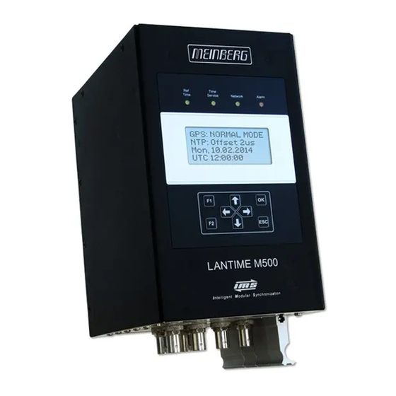
- Page 3 Front view (Frontansicht) IMS - LANTIME M500 DEUTSCH Status LEDs: Ref. Time, Time Service, Network, Alarm LC Display, 4 x 16 Zeichen Funktionstasten: 4-Wege Navigationstasten; F1, F2, OK, ESC ENGLISH Status LEDs: Ref. Time, Time Service, Network, Alarm LC Display, 4 x 16 characters Function buttons: 4-way navigation button;...
- Page 4 Bottom view (Ansicht Unterseite) IMS - LANTIME M500 1 - PWR 2 - CLK 3 - MRI 4 - ESI 5 - CPU 6 - CES DEUTSCH PWR Netzteil (100-240 V AC / 100-200 V DC) GPS Satellitenempfängermodul LAN-CPU RJ45 - 10/100/1000 Base-T SFP - 1000Base-T RJ45 Terminal und USB Chassis Erweiterungs-Slot...
-
Page 5: Table Of Contents
Table of Contents 1 Imprint 2 The System IMS-M500 IMS - Systems ..........Target Audience . - Page 6 10.5 NTP and IEEE 1588-PTP online tutorials ....... . 10.6 The Meinberg Academy introduction and offerings ......
-
Page 7: Imprint
1 Imprint 1 Imprint Meinberg Funkuhren GmbH & Co. KG Lange Wand 9, 31812 Bad Pyrmont / Germany Phone: + 49 (0) 52 81 / 93 09 - 0 Fax: + 49 (0) 52 81 / 93 09 - 230 Internet: https://www.meinbergglobal.com... -
Page 8: The System Ims-M500
2.3 Return of Equipment All parts and components of your Meinberg system may only be repaired by Meinberg. In the event of a malfunction, the customer must contact our support service and never attempt to repair the device himself. -
Page 9: Ims-M500 System Description
3 IMS-M500 System Description 3 IMS-M500 System Description 3.1 Device Design, Functions and Area of Application The IMS-LANTIME-System is a set of equipment composed of a reference module, a single-board computer module (LAN-CPU) with integrated network card, and a power supply unit, all installed in a modular chassis and ready to operate. -
Page 10: Ims System Variants
3.2 IMS System Variants The IMS system variants differ primarily in their housing form. 19 inch rack mount chassis The base chassis contains a power supply, a receiver and the LANTIME CPU. This provides further slots for additional input and output modules. M1000(S): four slots for expansion cards three slots for expansion cards in redundant receiver configuration... -
Page 11: Hardware Specifications
3 IMS-M500 System Description 3.3 Hardware Specifications 3.3.1 Chassis Variants The IMS systems are offered in several housing variants. The hardware configuration is modular and the number of input and output options depends on the respective housing variant. IMS system Type Dimension* IO Slots... -
Page 12: Environmental Requirements
3.3.2 Environmental Requirements Protection Rating: IP20 Ambient Temperature: 0 ... 50 C Storage Temperature: -20 ... 70 C Humidity: max. 85% (non-condensing) @ 30 C Please Note: To prevent overheating damage during operation, some IMS systems are equipped with an active cooling mod- ule (ACM). -
Page 13: Important Safety Information
Meinberg Funkuhren shall not be responsible for any damage arising due to non-observance of these regulations. -
Page 14: Used Symbols
4.2 Used Symbols The following symbols and pictograms are used in this manual. To illustrate the source of danger, pictograms are used, which can occur in all hazard classes. Symbol Beschreibung / Description IEC 60417-5031 Gleichstrom / Direct current IEC 60417-5032 Wechselstrom / Alternating current IEC 60417-5017 Erdungsanschluss / Earth (ground) terminal... - Page 15 The product manuals are stored on a USB stick, which is delivered with the system. The manuals can also be downloaded from the Meinberg website https://www.meinbergglobal.com. Enter the respective system name into the search box at the top of the page.
-
Page 16: Security During Installation
4.3 Security during Installation WARNING! Preparing for Commissioning This built-in unit, has been designed and examined according to the requirements of the standard IEC 62368-1 "Audio/video, information and communication technology equipment - Part 1: Safety requirements". When the built-in unit is used in a terminal (e.g., housing cabinet), additional requirements according to Standard IEC 62368-1 must be observed and complied with. - Page 17 4 Important Safety Information Connecting Data Cables During a thunderstorm, data transmission lines must not be connected or disconnected (risk of lightning). When wiring the devices, the cables must be connected or disconnected in the order of the arrangement described in the user documentation accompanying the device. Always attach all cables to the plug during connection and removal.
- Page 18 AC Power Supply DC Power Supply The device is a device of protection Outside the assembly group the device must be • • class 1 and may only be connected to a disconnectable from power supply grounded outlet (TN system). accordance with the provisions of IEC 62368-1 For safe operation, the device must be (e.g.
-
Page 19: Protective Conductor- / Ground-Terminal
4 Important Safety Information 4.4 Protective Conductor- / Ground-Terminal ATTENTION! In order to ensure safe operation and to meet the requirements of IEC 62368-1, the device must be correctly connected to the protective earth conductor via the protective earth connection terminal. If an external earth connection is provided on the housing, it must be connected to the equipotential bonding rail (grounding rail). -
Page 20: Safety During Maintenance
4.6 Safety during Maintenance WARNING! When you are expanding the device, use only device parts that are approved for the system. Non-observance may result in injury to the EMC or safety standards and cause malfunction of the device. If device parts, which are released for the system, are extended or removed there may be a risk of injury in the area of the hands, due to the pull-out forces (approx. -
Page 21: Cleaning And Care
4 Important Safety Information 4.8 Cleaning and Care ATTENTION! Do not wet clean the appliance! Penetrating water can cause considerable dangers to the user (e.g., electric shock). Liquid can destroy the electronics of the device! Liquid penetrates into the housing of the device and can cause a short circuit of the electronics. -
Page 22: Return Of Electrical And Electronic Equipment
Return and Collection Systems For returning your old equipment, please use the country-specific return and collection systems available to you or contact Meinberg. The withdrawal may be refused in the case of waste equipment which presents a risk to human health or safety due to contamination during use. -
Page 23: Before You Start
5 Before you start 5 Before you start 5.1 Text and Syntax Conventions This chapter briefly describes the text and syntax conventions used in this manual. Menu description Example web interface menu "Network Submenu "Network Physical Network Configuration" Tab in a submenu "Network Network Interfaces IPv4"... -
Page 24: Abbreviation List
5.2 Abbreviation List AFNOR Association Francaise de range (PTP) Normalisation time codes Internet Protocol Alternating Current IP 20 Protection Class 20 ASCII American Standard Code for IRIG Inter-range instrumentation group Information Interchange time codes Best Master Clock Liquid Crystal Display Bayonet Neil Councilman connector LDAP(S) Lightweight Directory Access Protocol... - Page 25 5 Before you start SHA-1 Secure Hash Algorithm 1 AFNOR or IEEE1344 codes Subminiature coaxial connector North American telecommunication SNMP Simple Network Management Protocol signal at 1.544 MHz frequency SNTP Simple Network Time Protocol Transmission Control Protocol SMTP Simple Mail Transfer Protocol Transistor-to-Transistor Logic Standard Positioning System Data Transmission...
-
Page 26: Required Tools
5.3 Required Tools LANTIME IMS SERIES LANTIME LANTIME LANTIME LANTIME LANTIME LANTIME LANTIME M1000 M1000S M2000S M3000 M3000S M4000 M500 Mounting TORX T20 TORX T20 TORX T20 TORX T20 TORX T20 TORX T20 Rackears Mounting Phillips DIN rail PH1 x 80 Replacing TORX T8 TORX T8... -
Page 27: Preparing Installation
5 Before you start 5.4 Preparing Installation Meinberg IMS LANTIME systems are designed for installation in 19-inch racks or 35mm rail mount. Rack systems come with all necessary accessories (mounting brackets, screws, adapters for power supply ...). For installations in regions outside of Germany that have other standards (e.g. for power supply connections), please specify exactly which adapters or cables you need to put the device into operation when ordering. -
Page 28: Unboxing The Device
5.5 Unboxing the Device After unpacking the LANTIME time server, please check the contents for completeness - regarding to the in- cluded packing list. M200 - optional M300/M600 LANTIME Package Contents ———————————————————————————————————- Assembly brackets for 19 Inch rack mounting (optional for LANTIME M200) Protection spacer (M200 / M300 / M600) Screws for brackets (M200 / M300 / M600) 3-pin DFK connector or 5-pin DFK connector... - Page 29 5 Before you start Mounting Kit for GPS Antenna (wall or pole mounting) ———————————————————————————————————- Mounting Kit for Long Wave Antenna (wall mounting) ———————————————————————————————————- Note: Please read the safety instructions and the manual carefully to familiarize yourself with the safe and proper handling of electronic devices. The product documentation can be found on the USB Flash Memory.
-
Page 30: Disposal Of Packaging Materials
5.6 Disposal of Packaging Materials The packaging materials we use are fully recyclable: Material Use for Disposal ———————————————————————————————————————— Polystyrol packaging frame/filling material Recycling Depot (polystyrene peanuts, bubble wrap) PE-LD accessories packaging Recycling Depot Polyethylene low density Cardboard shipping packaging, Paper recycling accessories packaging ————————————————————————————————————————... -
Page 31: System Installation
6 System Installation 6 System Installation 35 mm Railmount The IMS-M500 system is equipped with a fixing clamp for DIN rail mounting (35 mm x 7,5 mm) at the rear. A plug connection for connection to a potential equalization rail is located below the fixing clamp. Please also refer to the chapter "Important Safety Information ->... -
Page 32: Antenna Connection
A detailed description of the reception modes of our reference clocks and instructions for antenna installa- tion can be found in our LTOS firmware manual: http://www.mbg.link/doce-fw-ltos in chapter "Antenna and Receiver Information". The following table shows the available receiver types from Meinberg Type Receiver Systems Antenna / signal reference ——————————————————————————————————————————————... -
Page 33: Mounting The Antenna
6 System Installation 6.1.1 Mounting the Antenna 6.1.1.1 Installation GPS Antenna WARNING! Antenna mounting without effective anti-fall protection Danger to life due to fall! - Pay attention to effective working safety when installing antennas! - Never work without an effective anti-fall equipment! WARNING! Working on the antenna system during thunderstorms Danger to life due to electrical shock! - Page 34 Antenna Mounting Mount the antenna at a distance of 50 cm from other Free view to the sky! antennas to a vertical pole up to 60 mm outer diameter or on a wall with the mounting kit included in the scope of delivery.
- Page 35 6 System Installation Earth cable to PE rail To ground the antenna cable, connect the surge Cable circa 1,5 mm Ø protection with a grounding cable to a equipotential attached to the surge protection bonding rail (see figure). After installation, connect the other end of the as short as possible antenna cable to the socket of the surge protection.
- Page 36 Antenna splitter option Several receivers can be connected to one antenna via the antenna splitter. Make sure, that the total length of a route going from the antenna via the splitter to the receiver, does not exceed the maximum cable length. The splitter may be installed at any position between the surge protector and the receiver.
- Page 37 6 System Installation 6.1.1.2 Installation GNSS Antennas For our combined GPS/GLONASS/Galileo/BeiDou satellite receivers, there are two available antennas, which are designed for different tasks or applications. Standard accessories include the active Multi GNSS L1 antenna, which can receive signals from GPS, GLONASS, Galileo and Beidou satellite systems.
- Page 38 Antenna Mounting Mount the antenna at a minimum distance of 50 cm Free view to the sky! from other antennas to a vertical pole with an outer diameter from 60 mm to 215 mm (2 inch) with the mounting kit included in the scope of delivery. GNSS Antenna Now connect the antenna cable to the N-Norm con- nector of the antenna.
- Page 39 6 System Installation Earth cable to PE rail To ground the antenna cable, connect the surge Cable circa 1,5 mm Ø protection with a grounding cable to a equipotential attached to the surge protection bonding rail (see figure). After installation, connect the other end of the as short as possible antenna cable to the socket of the surge protection.
- Page 40 Antenna splitter option Several receivers can be connected to one antenna via the antenna splitter. Make sure, that the total length of a route going from the antenna via the splitter to the receiver, does not exceed the maximum cable length. The splitter can be installed at any position between antenna or, if used, the surge protector and receiver.
- Page 41 6 System Installation 6.1.1.4 Installation of the RV-76G GPS/GLONASS Antenna for mobile Applications Mounting the antenna Source: Datasheet gps-glonass_antenna_rv-76g_catalog_v1.pdf (Sanav) IMS - LANTIME M500 Date: 28th May 2021...
- Page 42 DCF77 long wave DCF77 Antenna Location: Mailand Figure: Antenna installation of a Meinberg AW02 antenna aligned to the DCF77 transmitter mast in Mainflin- gen (Frankfurt/Main). A DCF77-reception in buildings is possible, but due to shielding or attenuation the reception quality can be reduced.
- Page 43 • Antenna installation under or near power lines Meinberg recommends mounting the antenna outside of buildings. This has the advantage that the signal-to- noise ratio to electronic devices in buildings is usually increased and the reliability of the synchronization is thus significantly improved.
- Page 44 DCF77 signal. Meinberg recommends that the alignment and the associated reception quality check be done in a team. A good method for aligning and testing a long wave antenna is to have person 1 (at the antenna) in contact with person 2 (at the receiver).
- Page 45 6 System Installation Outdoor installation Indoor installation High voltage peaks (e.g. caused by lightning strikes) (recommended) Inside a waterproof housing. can be transmitted via the antenna cable and may Just after the antenna cable enters the wall. cause damage to the receiver. The receiver is pro- tected against these effects by using the MBG S-PRO surge protection.
- Page 46 The next step is to connect the supplied coaxial cable between the surge protector and receiver. N-Norm (female) N-Norm (male) Receiver Optional Antenna splitter SMA (male) SMA (female) BNC (male) BNC (female) N-Norm (male) N-Norm (female) Date: 28th May 2021 IMS - LANTIME M500...
- Page 47 6 System Installation Antenna splitter option We recommend to install an antenna distributor between antenna and receiver if the cable length exceeds 300 m. This serves on the one hand as an antenna distributor (DCF AV4) so that several receivers can be connected to one antenna and on the other hand as an amplifier of the antenna signal.
-
Page 48: Connecting The System
6.2 Connecting the System Make sure that the system to be connected is connected to your PC or the network via either a serial or a network connection and is on the same physical network. SERIAL CONSOLE GNSS ANTENNA NETWORK AC/DC POWER Figure: Connection scheme LANTIME M500 with power supply, network connector, serial connection and... -
Page 49: Initial Network Configuration
6 System Installation 6.3 Initial Network Configuration After the system has been connected to the power supply and to the receiver antenna, the initial start-up can be started. The device starts immediately after connection to the power supply. An IMS LANTIME system is shipped with DHCP service enabled on the LAN 0 interface. This means that you have to establish a manual network connection if no DHCP service is installed in your network environment in order to perform system settings via the web interface. - Page 50 VT100. Computers without serial interface can be connected with a "Serial-to USB" converter. After connection is established, the prompt for the user ID should be displayed: Welcome to Meinberg LANTIME login: _ Default user: root...
-
Page 51: System Operation - Configuration And Monitoring
7 System Operation - Configuration and Monitoring 7 System Operation - Configuration and Monitoring The LANTIME web interface. You have access to all NTP servers of the LANTIME M series via the LANTIME web interface. To connect simply enter the set IP address of your LANTIME system into the address line of a standard web browser. A login dialog will open - in delivery state you can use the following login data: User: root Password: timeserver... -
Page 52: Maintenance, Servicing And Repairing
8 Maintenance, Servicing and Repairing 8.1 Firmware Updates On our firmware download page at: https://www.meinbergglobal.com/english/sw/firmware.htm we provide the latest version of the LANTIME firmware for free download. If you need an older version, then you can request it from our support. To do so, select the option "A specified firmware version" and then enter the version of the currently used firmware and the desired firmware version (e.g. -
Page 53: Troubleshooting And Alarming
9 Troubleshooting and Alarming 9 Troubleshooting and Alarming If there is a problem with your IMS LANTIME system, you can contact our technical support at any time. In order to perform a fast and targeted diagnosis of your system please provide us with a diagnostic file of the affected LANTIME system. -
Page 54: System Error Messages
9.1 System Error Messages System messages and notifications. In the web interface menu "Main" under System Messages and in the menu "Notification Notification Events" you are able to view the last system notifications and the triggered event notifications. For the system messages the date and UTC time is displayed, for the notifications the date and UTC time of the last occurrence of the triggered event is displayed. -
Page 55: Support Information
10 Support information In this chapter you will learn about different levels of support at the Meinberg Company. In general, the Basic Customer Support level is included in the price you pay for your Meinberg product and demands no additional costs. -
Page 56: Basic Customer Support
10.2 Support Ticket System Meinberg assists you quickly and directly on questions regarding the initial setup of your devices, troubleshoot- ing or if you want to update the hard- or software. We offer free support for the whole lifetime of your Meinberg product. -
Page 57: How To Download A Diagnostic File
10 Support information 10.3 How to download a Diagnostic File In most support cases the first action is to ask the customer to download the diagnostic file, because it is very helpful at identifying the current state of the LANTIME and finding possible errors. Therefore we recommend that you attach your Diagnostic File when sending a ticket to our support. -
Page 58: Self-Help Online Tools
10.4 Self-Help Online Tools Here is the list of some informative websites where you can query different information about the Meinberg Systems. Meinberg Homepage - general: https://www.meinbergglobal.com/ NTP Download - at Meinberg: https://www.meinbergglobal.com/english/sw/ NTP Client Download for Windows (NTP-time-server-monitor): https://www.meinbergglobal.com/english/sw/ntp-server-monitor.htm LANTIME firmware update request online form:... -
Page 59: The Meinberg Academy Introduction And Offerings
10 Support information 10.6 The Meinberg Academy introduction and offerings Meinberg Sync Academy (MSA) is an institution within the Meinberg Company which takes care for education and expert knowledge dissemination in the field of time and frequency synchronization. The academy offers tutorials and courses on the latest synchronization technologies such as NTP, IEEE 1588-PTP, synchronization networks for different industries: telecom, power, broadcasting, professional audio/video, finance, IT and . -
Page 60: Technical Appendix
11 Technical Appendix 11.1 Technical Specifications LANTIME / IMS-M500 Housing: Metal desktop case, DIN Mounting Rail (35 mm x 7,5 mm) 117.5 mm (4.63 inch) x 193.2 mm (7.61 inch) x 159.8 mm (6.29 inch) / W x H x D with module handles and connectors: 117.5 mm (4.63 inch) x 228.2 mm (8.95 inch) x 159.8 mm (6.29 inch) / W x H x D 117.5 mm [ 4.63 in ]... -
Page 61: Available Modules And Connectors
11 Technical Appendix 11.2 Available Modules and Connectors Name Type Signal Cable ——————————————————————————————————————————— Front Connectors Terminal 9pin D-SUB male RS-232 shielded data line USB Port USB Stick Rear Connectors Power supply 5pin DFK male 100-240 V AC (50-60Hz) 5pin MSTB clamp 100-200 V DC GPS Antenna 10 MHz / 35.4 MHz... - Page 62 Name Type Signal Cable ——————————————————————————————————————————— Signal Inputs: BNC, RJ45 E1/T1, var. Freq. shielded data line 10 MHz, PPS, IRIG, PP shielded data line Video Sync, LTC, Word Clk shielded data line and PPS Input Chassis Expansion Slot DFK-3 Error Relay Date: 28th May 2021 IMS - LANTIME M500...
-
Page 63: Terminal (Console)
11 Technical Appendix 11.3 TERMINAL (Console) To connect a serial terminal (according to the device model), use the 9pin RS-232 D-Sub connector in the front panel or the RJ45 connector of the LAN-CPU. Via the serial terminal connection it is possible to con- figure parameters with a command line interface. -
Page 64: Replacement Or Installation Of A Hot-Pluggable Ims Module
11.5 Replacement or Installation of a Hot-pluggable IMS Module If the system is supplied with an antenna and antenna cable, it is advisable to first mount the antenna in a suitable location (see chapter Antenna Mounting) and lay the antenna cable. Please use a Torx screwdriver (T8 x 60) for removal and installation of the module. -
Page 65: Important Hints For Hot-Pluggable Ims Modules
11 Technical Appendix 11.5.1 Important Hints for hot-pluggable IMS Modules The following points should be strictly observed when replacing IMS modules during operation. Not all IMS modules are fully hot-pluggable. Of course, it is not possible to replace a power supply unit of a non-redundant system without first having installed a second power source in operational mode. -
Page 66: Ims Module Options
11.6 IMS Module Options 11.6.1 IMS M500 Slot Assignment The IMS system LANTIME M500 has a chassis for DIN rail mounting. One slot each is available for the power supply, the receiver and the LAN CPU. In addition, the M500 system offers two input slots for ESI and MRI modules. -
Page 67: Power Supply 100-240 V Ac / 100-200 V Dc
11 Technical Appendix 11.6.2 Power Supply 100-240 V AC / 100-200 V DC Connector Type: 5-pol. DFK Pin Assignment: 1: N/- 2: not connected AD10 3: PE (Protective Earth) 4: not connected 5: L/+ 100-240 V Input Parameter = 90 -265 V = 1.0 A ——————————————————————————... -
Page 68: Power Supply 20-60 V Dc
11.6.3 Power Supply 20-60 V DC Connector: 5pin DFK Pin Assignment: not connected DC20 PE (Protective Earth) not connected Input Parameter = 24-48 = 20-60 ——————————————————————————– = 2.1 A Nominal voltage range: 24-48 V Maximum voltage range: 20-60 V Nominal current: 2.1 A Output Parameter ——————————————————————————–... -
Page 69: Power Supply 10-36 V Dc
11 Technical Appendix 11.6.4 Power Supply 10-36 V DC Connector: 5pin DFK Pin Assignment: not connected DC10 PE (Protective Earth) not connected Input Parameter = 24 = 10-36 ——————————————————————————– = 2.5 A Nominal voltage: 24 V Maximum voltage range: 10-36 V Nominal current: 2.5 A Output Parameter... -
Page 70: Gps Clock
11.6.5 GPS Clock Receiver: 12 channel GPS C/A-code receiver Accuracy Depends on oscillator option: of pulse outputs: < +-100 ns (TCXO, OCXO LQ) < +-50 ns (OCXO-SQ, -MQ, -HQ, -DHQ) Antenna Cable: shielded coax Cable Length: max. 300 m to RG58, max. - Page 71 5 s (active high) Pin 2: String The following timestrings (time telegrams) can be used: - NMEA RMC - NMEA ZDA - Meinberg Standard - Uni Erlangen Pin Assignment of the optional XHE-SPI Connectors: A1: PPS In A2: PPS Out...
-
Page 72: Gnss Clock
11.6.6 GNSS Clock Type of receiver: GPS / GLONASS / Galileo / Beidou receiver Number of channels: 72 Frequency band: GNSS L1 1575.42 +- 10 MHz / 1602-1615 MHz Accuracy of Pulses: Dependant on oscillator option < +-100 nsec (TCXO, OCXO-LQ) <... - Page 73 5 s (active high) Pin 2: String The following timestrings (time telegrams) can be used: - NMEA RMC - NMEA ZDA - Meinberg Standard - Uni Erlangen Pin Assignment of the optional XHE-SPI Connectors: A1: PPS In A2: PPS Out...
-
Page 74: Gns-Uc Clock
11.6.7 GNS-UC Clock GNSS receiver with UpConverter for operation on a standard Meinberg GPS antenna/converter unit. Type of receiver: GPS / Galileo receiver Number of channels: 72 GPS: L1C/A Galileo: E1B/C 181-UC 181-UC Accuracy of Pulses: Dependant on oscillator option <... - Page 75 5 s (active high) Pin 2: String The following timestrings (time telegrams) can be used: - NMEA RMC - NMEA ZDA - Meinberg Standard - Uni Erlangen Pin Assignment of the optional XHE-SPI Connectors: A1: PPS In A2: PPS Out...
-
Page 76: Gnm Clock
11.6.8 GNM Clock Receiver Type 184-channel GPS, GLONASS, Galileo, Beidou Frequency Band: GPS: L1C/A (1575.42 MHz) L2C (1227.60 MHz) GLONASS: L1OF (1602 MHz + k*562.5 kHz L2OF (1246 MHz + k*437.5 kHz k = –7,..., 5, 6 Galileo: E1-B/C (1575.42 MHz) E5b (1207.140 MHz) Beidou: B1I (1561.098 MHz) B2I (1207.140 MHz) - Page 77 5 s (active high) Pin 2: String The following timestrings (time telegrams) can be used: - NMEA RMC - NMEA ZDA - Meinberg Standard - Uni Erlangen Pin Assignment of the optional XHE-SPI Connectors: A1: PPS In A2: PPS Out...
-
Page 78: Pzf Clock
11.6.9 PZF Clock Receiver: High accuracy DCF77 correlation receiver Two seperate receiver channels for signal conversion and best aquisition and tracking of the DCF77 signal (AM + PZF). Synchronization Time: 2-3 minutes after correct DCF77 signal reception Frequency Outputs: Accuracy depends on oscillator (standard: OCXO-SQ) Pulse Outputs: Pulse per second (PPS) and pulse per minute (PPM). - Page 79 Signal level: TTL Pulse length: 5 s (active high) Pin 2: String The following timestrings (time telegrams) can be used: - NMEA RMC - NMEA ZDA - Meinberg Standard - Uni Erlangen IMS - LANTIME M500 Date: 28th May 2021...
-
Page 80: Tcr Clock - Time Code Reader And Generator
11.6.10 TCR Clock - Time Code Reader and Generator The IMS - TCR180 serves to decode and generate mod- ulated (AM) and unmodulated (DC Level Shift) IRIG- A/B/G, AFNOR, C37.118 or IEEE1344 time codes. AM-codes are transmitted by modulating the ampli- tude of a sine wave carrier, unmodulated codes by variation of the width of pulses. - Page 81 11 Technical Appendix Generator: The generator of TCR180 is capable of producing time codes in IRIG-A/B/G, AFNOR, C37.118 or IEEE1344 format. The codes are available as modulated (3 V /1 V into 50 ) and unmodulated (DC Level Shift) signals (TTL into 50 and RS-422).
- Page 82 7E2, 8N1, 8N2, 8E1, 7N2, 7E1, 801 Mode of operation: string per second string per minute string on request Time telegram: Meinberg Standard, Uni Erlangen, SAT, Meinberg Capture, ION, Computime, SPA, RACAL Capture Inputs Triggered by falling TTL slope Pulse repetition time: 1.5 msec min.
- Page 83 Signal level: TTL Pulse length: 5 s (active high) Pin 2: String The following timestrings (time telegrams) can be used: - NMEA RMC - NMEA ZDA - Meinberg Standard - Uni Erlangen IMS - LANTIME M500 Date: 28th May 2021...
-
Page 84: Lan-Cpu
11.6.11 LAN-CPU As the central management and control element, the CPU module in an LANTIME system is responsible for management, configuration and alarm notifications. It additionally provides NTP and SNTP services on its network interface. Technical specifications IMS LAN CPU C05F1 Processor: AMD Geode LX 800 Processor,... - Page 85 11 Technical Appendix Status LEDs: —————————————————————————– LAN 0 LED - Connect, Activity and Speed of the network connection R (Receiver) green: the reference clock (e.g. build-in GNSS) provides a valid time red: the reference clock does not provide a valid time T (Time Service) green: NTP is synchronized to the...
-
Page 86: Mri - Standard Reference Input Signals
11.6.12 MRI - Standard Reference Input Signals If an application requires to use external synchronization sources instead of radio/GNSS signals, an MRI card enables the installed clock module to synchronize to 1PPS, 10 MHz, DCLS and AM time codes (IRIG B, AFNOR, IEEE1344 or C37.118). - Page 87 11 Technical Appendix Status Indicators LED St: MRI status LED In: Status of the backplane’s reference signals LED A: Status of the input signals (TC-AM/DCLS) at the board LED B: Status of the input signals (10 MHz/PPS) at the board Initialisation: LED St: blue until USB is configured LED In - LED B: off...
- Page 88 11.6.12.1 Configuration of Input Signals Four fixed input signals (time code AM, time code DCLS, 10 MHz and PPS) can be supplied via the MRI module to synchronize the system. MRS prioritization The provided input signals can be configured and monitored after the module is initialized. MRS setting: selection and prioritization of the available input sources.
-
Page 89: Esi - Telecom Synchronisation References
11 Technical Appendix 11.6.13 ESI - Telecom Synchronisation References Enhanced Synchronisation Inputs Reference Inputs: PPS and variable frequencies unframed, 1 kHz - 20 MHz 2,048 Mbit/s / 1,544 Mbit/s - E1/T1 framed Input 1 1PPS (BNC female connector) TTL, pulse duration 5 s, active high Input 2 1 kHz - 20 MHz (BNC female connector) - Page 90 Pin assignment of the RJ-45 jacks (input 3 + 4) 11.6.13.1 ESI Configuration via Web Interface ESI – External Synchronization Input Menu "IO Config -> Input Configuration -> ESI - External Synchronization Interface" The ESI (External Synchronization Input) card is capable of adding additional synchronization sources to an IMS system.
- Page 91 11 Technical Appendix Input 2: accepts as input signal configurable frequencies from 1 kHz to 20 MHz. Type: Freq. In Frequency: Fill in a configurable frequency, 10 MHz is set as default value. Maximum Slip in Cycles: A discontinuity of an integer number of cycles in the measured carrier phase resulting from a temporary loss of input signal.
- Page 92 Input 4: BITS In: As fixed frequency you can choose between E1 framed or T1 framed Minimum Quality Levels: Synchronization Status Message (SSM) in accordance with ITU G.704-1998 standard includes 4 bit long SSM quality messages received via incoming E1 framed signal. The clock source quality levels according to G.704-1998 are as follows: QL-STU/UKN Quality unknown, existing synchronization network...
-
Page 93: Vsi - Video Synchronization Input Card
11 Technical Appendix 11.6.14 VSI - Video Synchronization Input Card Video signal input module The VSI (Video Synchronization Input) card provides video signals to an IMS clock module as reference. It can process Black Burst (PAL), LTC (Linear Time Code) and programmable Word Clock Rates. Connectors: 4 x BNC female Input Signal:... - Page 94 Status Indicators LED St: Status of VSI180 LED In: Synchronization status LED A No function LED B: No function Operation conditions: Initialisation: LED St blue during initialization green during operation LED In: Shows status after initialization Green Accurate Green Flashing Timesync Yellow Insufficient quality of the reference signal.
- Page 95 11 Technical Appendix 11.6.14.1 Configuration of VSI180 via Webinterface VSI - Video Signal Input References Menü "IO Config Input Configuration VSI-Module" Video Sync Interface: configurable Inputs Input 1: Video Sync In Format: PAL 625i Epoch: Signal Source: Single-ended signal input Time Code Modes: VITC Time Code Line:...
- Page 96 Input 2: LTC In Type: LTC 25 FPS (Frames per Second) Input 3: Word Clk In Frequency: 1 kHz - 10 MHz Max Slip: 0.5 - 3.0 oscillations Date: 28th May 2021 IMS - LANTIME M500...
- Page 97 11 Technical Appendix Input 4: PPS In Pulse length: 5 s, active high 11.6.14.2 Status Monitoring of the IMS-VSI The submenu "Status" of the "IO Config" allows you to view the status of each port of the installed IMS-VSI module. In addition, the current operating temperature of the module is displayed in this menu. IMS - LANTIME M500 Date: 28th May 2021...
- Page 98 11.6.14.3 Status Monitoring of the IMS-VSI The submenu "Status" of the "IO Config" allows you to view the status of each port of the installed IMS-VSI module. In addition, the current operating temperature of the module is displayed in this menu. Date: 28th May 2021 IMS - LANTIME M500...
-
Page 99: Lne-Gbe: Network Expansion With Gigabit Support And Sfp Option
11 Technical Appendix 11.6.15 LNE-GbE: Network Expansion with Gigabit Support and SFP Option Link speed: 10/100/1000 Mbita Connector Type: 8P8C (RJ45) Cable: CAT 5.0 Duplex Modes: Half/Full/Autonegotiaton LED Indicators LED St: Init lights blue during initialisation LED In - LED B: Shows the state of the four LAN ports after initialisation green normal operation defective LAN port... - Page 100 Recommended and tested Transceivers from other Vendors Mode Vendor/Type Distance ———————————————————————————————————————– MULTI MODE: AVAGO AFBR-5710PZ 550 m FINISAR FTLF8524P3BNL 500 m SINGLE MODE: AVAGO AFCT-5710PZ 10 km FINISAR FTLF1318P3BTL 10 km SMARTOPTICS SO-SFP-L120D-C63 80 km RJ-45: AVAGO ABCU-5740RZ 100 m FINISAR FCLF8521P2BTL 100 m LAN interface alignment with several LNE modules in operation:...
- Page 101 11 Technical Appendix 11.6.15.1 LNE-GBE Configuration via the Web Interface If the LNE-GBE operates in an LANTIME system, all network settings can be configured via the web interface then. Physical Network Configuration Net Link Mode: The network interfaces LAN1 - LAN4 (LNE-GBE) can be used in 1000 MBIT HALF / FULL duplex mode.
- Page 102 Menu Interfaces IPv4: Manually adjustment of all important parameters such as TCP / IP address, subnet mask and gateway. The DHCP client can also be activated here for automatic network configurations. Misc: With the tab Misc the virtual interface can be assigned to a physical interface. VLAN: With VLAN, this function can be enabled and configured.
- Page 103 11 Technical Appendix 11.6.15.2 Adding / Removing an LANTIME Network Extension LNE An LNE module can be installed in each MRI/ESI or IO Slot of a LANTIME IMS device. Adding a LANTIME Network Extension After installing the LNE module, please start the web interface. In the menu "System Services and Functions"...
-
Page 104: Hps-100: Ptp / Synce / Hardware Ntp Interface
11.6.16 HPS-100: PTP / SyncE / Hardware NTP Interface IEEE 1588 v2 compatible Profiles: IEEE 1588v2 Default Profile IEEE 1588v1 (option) Enterprise Profile IEC 61850-9-3 Power Profile IEEE C.37.238-2011 Power Profile IEEE C.37.238-2017 Power Profile ITU-T G.8265.1 Telecom Frequency Profile ITU-T G.8275.1 Telecom Phase / Time Profile (full timing support) ITU-T G.8275.2 Telecom Phase / Time Profile (partial timing support) SMPTE ST 2059-2 Broadcast Profile... - Page 105 11 Technical Appendix LED Indicators LED St: Init lights blue during initialisation, off in normal operation mode LED In: Error - TSU does not work correctly, PTP services stopped yellow No link, but initialized green link up stopped LED A - LED B: Shows the current State of the TSU yellow - yellow Listening green - off...
- Page 106 A detailed configuration guide you will find in the corresponding firmware manual of the system. See chapter "The Web Interface -> Configuration: PTP V2". Figure: Webinterface - PTP Menu Global Configuration Date: 28th May 2021 IMS - LANTIME M500...
-
Page 107: Tsu V3: Ieee-1588 Time Stamp Unit
11 Technical Appendix 11.6.17 TSU V3: IEEE-1588 Time Stamp Unit TSU v3 (IEEE 1588 v2 compatible) Profiles: IEEE 1588v2 Default Profile IEEE C.37.238 Power Profile ITU-T G.8265.1 Telecom Frequency Profile ITU-T G.8275.1 Telecom Phase/Time Profile SMPTE ST 2059-2 Broadcast Profile PTP Modes: Multicast Layer 2 (IEEE 802.3) Multicast/Unicast Layer 3 (UDP IPv4/IPv6) - Page 108 LED Indicators LED St: Init lights blue during initialisation, off in normal operation mode LED In: Error - TSU does not work correctly, PTP services stopped yellow No link, but initialized green link up stopped LED A - LED B: Shows the current State of the TSU yellow - yellow Listening green - off...
-
Page 109: Pio180 - Pps Or 10 Mhz I/O Module
11 Technical Appendix 11.6.18 PIO180 - PPS or 10 MHz I/O Module Technical Specifications: Connectors: 4 x BNC female, isolated, individually switchable as input or output Signal Options: PPS or 10 MHz St In P C Status Indicators LED St: PIO status LED In: Status of the backplane’s output signals... - Page 110 11.6.18.1 Pre-selection (PPS, 10 MHz) Before installing the PIO180 module, select the required signal using the jumper setting (PPS or 10 MHz). Upon delivery all ports are preset to PPS (Pulse Per Second). Mixed operation is not possible. All inputs/outputs are set to either PPS or 10 MHz 11.6.18.2 PIO - Configuration via the Web Interface In the "IO Config"...
- Page 111 11 Technical Appendix Via the web interface, each port can be set separately to "Input" or "Output". If a port is set to "Output", the system PPS or the 10 MHz reference frequency is output signal at this port. If a port is set to "Input" the incoming signal is compared to the system PPS or to the 10 MHz reference frequency.
-
Page 112: Cpe And Bpe Output Modules (Frontend - Backend, Eurocard)
11.6.19 CPE and BPE Output Modules (Frontend - Backend, Eurocard) Configurable Port Expander / Backplane Port Expander The standard output signals like pulses (1PPS, 1PPM and freely programmable pulses) and frequencies (10MHz, 2.048MHz, frequency synthesizer 1kHz-10MHz) are provided by two versatile I/O cards named BPE and CPE. Both of these two modules have been designed to cover a wide range of interface and signal/protocol require- ments. - Page 113 11 Technical Appendix 11.6.19.1 BPE - Backplane Port Expander Please Note: In principle, it should be noted that the signals that are provided via a BPE at the various connectors are always generated by the upstream clock and spread via the backplane of the system. In opposite to the CPE, the signals are not generated by the module and therefore the outputs can only be set via the receiver.
- Page 114 11.6.19.2 Available BPE Modules BPE Type Connectors Signals Size BPE-1040 4 x BNC female Out 1 - Out 4: TC AM BPE-1060 4 x BNC female Out 1 - Out 4: DCF77 SIM BPE-2000 4 x BNC female Out 1: PPS, Out 2: 10 MHz Out 3: TC DCLS, Out 4: TC AM BPE-2001 4 x BNC female...
- Page 115 11 Technical Appendix BPE Type Connectors Signals Size BPE-2110 8 x BNC female Out 1 - Out 8: PPS BPE-2120 8 x BNC female Out 1 - Out 8: 10 MHz BPE-2180 8 x BNC female Out 1 - Out 8: 2048 kHz BPE-2500 4 x 2pin DFK Out 1 - Out 4: Progr.
- Page 116 BPE Type Connectors Signals Size BPE-4043 4 x RJ45 RS422, Pin_3 T-, Pin_6 T+ BPE-6042 2 x DMC 16-pin 10 x PPO - RS-422 galvanic isolated Fiber-Optical Outputs BPE-5000 4 x FST PPS, 10 MHz, TC-DCLS, 2048 kHz FO Multimode BPE-5010 4 x FST PPS / FO Multimode...
- Page 117 11 Technical Appendix 11.6.19.3 Configuring an BPE expansion card via the Web Interface A simple BPE expansion card usually gets its signals directly from the internal backplane of the system. The output signals of the card are pre-configured according to customer requirements. If an output signal has to be changed, this must be done via the pre-connected receiver - in the menu "Clock Switch Card"...
- Page 118 11.6.19.4 BPE-8000 - Switchable Backplane Port Expander Output Signals: adjustable via the web interface (TTL or Fiber Optical): PPS, 10 MHz, 2048 kHz, TC-DCLS, Progr. Pulses or fixed: 2048 kHz (ITU G.703-15), TC-AM Power Requirements: 5 V +-5%, 150 mA / BNC 5 V +-5%, 150 mA / FO Status Indicators LED St:...
- Page 119 11 Technical Appendix Available BPE-8000 Models 8000 8100 8200 8300 8400 8500 8600 8700 4 x TTL 4 x FO MMF 2 x FO MMF 4 x FO SMF 2 x FO SMF 2 x FO MMF 4 x 2.048MHz 3 x TTL via BNC via ST...
- Page 120 11.6.19.5 Configuring an BPE-8000 expansion card via the Web Interface Via the web interface or the Meinberg Device Manager (MDU), the following signals can be distributed to the BNC connectors (TTL) or fiber optical connectors (ST) according to your choice: PPS, 10MHz, Time Code DCLS, 2048 kHz and programmable pulse outputs PP 1 - PP 4 of the upstream reference source.
- Page 121 11 Technical Appendix 11.6.19.6 BPE-1060 4 x SIM77 (-60 dBm) Backplane Port Expander (Frontend / Backend) Output Signals: fixed: Out 1 - Out 4: SIM77 (DCF77 compatible Signal) via isolated female BNC connectors (-60 dBm) Power Requirements: 5 V +-5%, 150 mA / BNC 5 V +-5%, 150 mA / FO Status Indicators LED St:...
- Page 122 SIM77 - amplitude-modulated time signal The amplitude-modulated time signal is compatible with the DCF77 signal, transmitted by the German long- wave transmitter. The SIM77 signal is provided via four DC insulated BNC sockets. Note: Important configuration parameters must be observed when using the BPE-1060 module in an IMS system. In the Web Interface, in the menu "Clock Programmable pulse outputs Prog.
- Page 123 11 Technical Appendix In the example below, several time zones are entered with the changeover rule for summer and winter time. Please note, that these settings will also affect other output modules which provide the programmable pulse output "Prog. Out 1". IMS - LANTIME M500 Date: 28th May 2021...
- Page 124 11.6.19.7 CPE - Configurable Port Expander (Frontend) CPE (Configurable Port Expander) The CPE is a configurable IO card that can autonomously generate additional output signals from the inte- grated system clock. This module consists of a half-size standard controller card (back-end) and a dockable port expander card (front-end), like this a wide variety of available programmable output signals and physical connections are possible, including various electrical and optical interfaces.
- Page 125 11 Technical Appendix 11.6.19.8 Available CPE Modules BPE Type Connectors Signals Size CPE-1000 4 x BNC female prog. pulses CPE-1002 1 x D-SUB9 Time Telegram, RS232 2 x BNC female Capture Inputs CPE-1040 4 x BNC female TC AM / BNC CPE-1050 4 x BNC female 3 x progr.
- Page 126 11.6.19.9 CPE-3000: Programmable Outputs via serial Interface The CPE-3000 module has two serial ports (COM A and B) for various output signals. The two interfaces can also be used for communication with other devices. The possible pin assignments and module types are listed below: CPE-3000 CPE-3010 CPE-3020...
- Page 127 11 Technical Appendix 11.6.19.10 CPE - Configuration via Web Interface If the CPE operates in an IMS system, the output configuration can easily be done via the web interface then. With the "Common" tab the time zone with the corresponding offset can be selected. CPE Configuration In the "IO Config"...
- Page 128 Figure: Menu Tab "IRIG Out" Selection of the IRIG code (IRIG DCLS only) Figure: Menu Tab "Prog. Out" Selection of the signal option for the programmable pulse output (PPO) The following programmable pulse outputs can be selected: Idle (not in use) Timer (3 switching-times On - Off) Single Shot...
- Page 129 The module CPE-4020 has two interfaces with RJ45-connector (COM A and B). These provide Time String + PPS with RS-422 level. The following configurations must be performed to correctly output the signals. Baud Rate 19200 Framing 4020 String Type Meinberg GPS Mode per second (PPS) Pin assignment Pin 3: TXD_P, serial interf. transmit pos. Pin 5:...
- Page 130 11.6.19.12 CPE-4020 Configuration via Web Interface If the CPE-4020 operates in an IMS system, the output configuration can easily be done via the web interface then. With the "Common" tab the time zone with the corresponding offset can be selected. Configuration: CPE-4020 In the "IO Config"...
- Page 131 11 Technical Appendix Figure: Selection of programmable pulse outputs IMS - LANTIME M500 Date: 28th May 2021...
-
Page 132: Liu - Line Interface Unit
11.6.20 LIU - Line Interface Unit Input signal: 2.048 MHz reference clock, TTL level Clock: T1 - 1.544 MHz E1 - 2.048 MHz A4000 A0004 Power T1 E1 Power T1 E1 BITS: Framed Outputs 1544 kBit/s or 2048 kBit/s (ESF - Extended Superframe) T1 - 1.544 MBit/s E1 - 2.048 MBit/s Outputs:... - Page 133 11.6.20.1 IMS-LIU Telecom Output Signals The board LIU (Line Interface Unit) was designed to convert the GNSS-locked standard frequency of a pre- connected Meinberg satellite controlled clock (GPS or GPS/GLONASS/Galileo/BeiDou) into several timing signals that can be used for various synchronization or measurement tasks.
- Page 134 11.6.20.2 Block Diagram LIU The following block diagram illustrates the functional principle of the board LIU: LIU V3 isolation framed outputs isolation T1.403/G703-9, USB/IMS balanced (or unbalanced), isolation interface 1.544 Mbps or 2.048 Mbps isolation isolation RS232 interface isolation clock outputs G703-13, balanced isolation 1544 kHz or 2048 kHz...
- Page 135 11 Technical Appendix 11.6.20.3 Telecom Signals These signals can be devided into two groups: the "clock" outputs and the "framed" outputs, that are provided by a framer and line interface device on the board LIU. All clock signals needed for generation of the ‘telecom outputs’...
- Page 136 11.6.20.4 Pulse templates The following pulse templates are required by ANSI (T1-mode) and CCITT (E1-mode) for output signals in telecom applications. The board LIU meets these recommendations. T1 (T.403): E1 (G.703): Date: 28th May 2021 IMS - LANTIME M500...
- Page 137 11 Technical Appendix 11.6.20.5 LIU - Configuration Samples The Line Interface Unit (LIU) is available in two different sizes and different output / connector options. All outputs of a module can be operate in either the E1 or T1 in mode. Signal output settings can be done during operation via the web interface.
- Page 138 11.6.20.7 IMS - LIU Configuration E1/T1 – generator available with 4 or 8 outputs Generation of reference clocks for synchronization tasks. The module LIU (Line Interface Unit) generates dif- ferent reference clock pulses which are derived from the GPS-locked master oscillator of a preconnected GPS clock.
- Page 139 11 Technical Appendix Sa Bits ITU-T Recommendations allow for bits Sa4 to Sa8 to be used in specific point-to-point applications (e.g. transcoder equipment) within national borders. The Sa4 bit may be used as a message-based data link for operation, maintenance and performance moni- toring.
-
Page 140: Lno - Sine Wave Outputs With Low Phase Noise
11.6.21 LNO - Sine Wave Outputs with low Phase Noise The LNO180 is a 10 MHz (5 MHz option) generator card, which provides sine signals with low phase noise to 4 external outputs. The card has a microprocessor system, which monitors the output signals and generates status signals for the upper-level management system accordingly. - Page 141 11 Technical Appendix Power Supply: 5 dBm +5V @ 550 mA (steady state), +5V @ 670 mA (warm up) 12 dBm: +5V @ 970 mA (steady state), +5V @ 620 mA (warm up) LED Status Indicators: All LEDs red Outputs disabled PLL not locked, OCXO in warm up phase 10 MHz reference not available...
-
Page 142: Fdm - Frequency Deviation Monitoring
11.6.22 FDM - Frequency Deviation Monitoring The module FDM180 was designed to calculate and monitor the frequency and its deviation in 50/60Hz power line networks. A preconnected reference is necessary that provides a serial time string and a PPS (pulse per second). The accuracy of the measurements is derived from these signals. - Page 143 11 Technical Appendix Input signal: Serial time string, PPS mains frequency, 70 - 270 V AC, 50Hz or 60Hz Interface: Two asynchronous serial RS-232 ports, COM0 and COM1 Baudrate: 1200, 2400, 4800, 9600, 19200, 38400, 57600, 115200 Baud Framing: 7N2, 7E1, 7E2, 8N1, 8N2, 8E1, 7O2 output and average: once per second or 100ms Output string: The frequency, frequency deviation, reference time, power line time...
-
Page 144: Rel1000 - Error Relay Module
Additional documentation for the REL1000: The setup guide supports you in a quick initial operation. https://www.meinberg.de/download/docs/manuals/english/ims-rel.pdf The LANTIME firmware manual provides a complete description of all configurations and status monitoring options of your Meinberg product. Download LTOS7 Firmware manual: http://www.mbg.link/doce-fw-ltos Date: 28th May 2021... - Page 145 11 Technical Appendix 11.6.23.1 Error Relay The illustration on the right shows the two switching states of an error relay. Technical specification Switching voltage max.: 220 V DC 250 V AC Switching current max.: Switching load max.: 60 W DC 62.5 VA AC Normal Operation Mode FCC surge breakdown voltage...
- Page 146 11.6.23.2 REL1000 - Status LEDs Status indicator LED St: Status of the REL1000 LED A: Status of Relais A LED B: Status of Relais B LED C: Status of Relais C St A B C The status messages are as follows: LED St: Blue During initialization...
- Page 147 11 Technical Appendix 11.6.23.3 Pre-selection Depending on whether the IMS system is redundantly equipped with RSC module and two reference clocks or with an SPT module with only one reference clock, different relay states can be selected. This must be selected by setting the jumper before installing the REL1000 module.
- Page 148 11.6.23.4 REL1000 - Configuration via the Web Interface The relays A + C of the REL1000 module can be switched via notifications events. If the jumpers and hardware configuration are set accordingly, a checkbox can be activated in the web interface menu "Notification tification Events"...
-
Page 149: Scg-U: Studio Clock Generator
11 Technical Appendix 11.6.24 SCG-U: Studio Clock Generator Add-On module for generating various audio frequen- cies (12 kHz, 32 kHz, 44.1 kHz, 48 kHz, 64 kHz, 88.2 kHz and 96 kHz), with only one 10 MHz input clock, for studio applications. The SCG Module provides four outputs with different frequencies. - Page 150 11.6.24.1 SCG-U: Configuration via Web Interface (Firmware version 6.19 or later) If the SCG-U operates in an IMS system, the module can be easily configured via the web interface then. Configuration Sample: SCG Output 3 In the "IO Configuration" menu each output frequency can be adjusted seperately. In the figure above the fol- lowing value is set: Frequency Out 3 = Base Frequency * Scale Frequency Out 3 = 44,1 kHz * 1/4...
-
Page 151: Scg-B: Studio Clock Generator Balanced
11 Technical Appendix 11.6.25 SCG-B: Studio Clock Generator Balanced The IMS-M500 is an additional card for generating "Digi-tal Audio Reference Signals" for studio applica- tions. The 25pin D-Sub female connector provides four DARS outputs, which can be configured via the web interface. - Page 152 11.6.25.1 SCG-B: Configuration via the Web Interface If the SCG-B is used in an IMS system you can easily configure the Studio Clock Generator via the Web Interface. Sample Configuration: Output 1 In the menu "IO Configuration" you can set the output on DARS for every output of the IMS-M500. The four available outputs can optionally be switched off.
-
Page 153: Vsg181 - Video Sync Generator
11 Technical Appendix 11.6.26 VSG181 - Video Sync Generator The VSG181 is used as a video signal reference for studio equipment and provides the generated signals at four BNC outputs. These are 1x Bi-Level Sync (Black Burst)/Tri-Level-Sync, 1x Longitudinal Time and Control Code (LTC), 1x Digital Audio Out (DARS), and 1x Word Clock In order to be able to provide high-precision output signals during the switchover of the RSC (IMS systems with redundant receivers), the VSG181 has its own oscillator. - Page 154 DARS Output Output signal: DARS Signal level: TTL, 2.5 V into 75 Signal type: Base frequencies: 44.1 kHz and 48 kHz Word Clock Output Output signal: Word Clock Signal level: TTL, 2.5 V into 75 Frequency range: 24 Hz - 12,288 MHz Base frequencies: 44.1 kHz and 48 kHz Scaling factor:...
- Page 155 11 Technical Appendix 11.6.26.1 VSG Configuration via Web Interface If the VSG operates in an IMS system, the module can be easily configured via the web interface then. Overview Configuration VSG Video Sync Generator Outputs 1-4 Output 1 ———————————————————————- Output Type: Video Out Epoch: TAI D1970-01-01 T00:00:00...
- Page 156 Output 2: ———————————————————————- Output Type: Video Out Epoch: like Output 1 Format: NTSC (525i) PAL (625i) Phase Offset: [Offset Value] ———————————————————————- Date: 28th May 2021 IMS - LANTIME M500...
- Page 157 11 Technical Appendix Output 3: ( VSG FW 2.05) ———————————————————————- Output Type: Video Sync Out Signal Type: SD H-Sync SD V-Sync SD Frame HD H-Sync HD V-Sync HD Frame HD Blank ———————————————————————- Output 3: (VSG FW 2.06 - LTOS V7 required) ———————————————————————- Output Type: LTC Out...
- Page 158 Output 4: ———————————————————————- Output Type: Digital Audio Out Signal Type: DARS (AES3id) ———————————————————————- With the menu tab "Misc", the configuration of the VSG can be stored directly in the EEPROM of the card. Date: 28th May 2021 IMS - LANTIME M500...
-
Page 159: Ces - Chassis Expansion Slot
11 Technical Appendix 11.6.27 CES - Chassis Expansion Slot Standard Basic Configuration: Error relay contact module for error indication of clock faults. DFK Connectors (3-pin CO/NO/NC). Additional available signals via BNC female connector: - PPS - 10 MHz - other signals on request These Signals are generated by the pre-connected clock. -
Page 160: Rohs And Weee
Any transportation expenses for return- ing this product (at its end of life) have to be incurred by the end user, whereas Meinberg will bear the costs for the waste disposal itself. Date: 28th May 2021... -
Page 161: Declaration Of Conformity
13 Declaration of Conformity Konformitätserklärung Doc ID: IMS - LANTIME M500-2021-05-27 Hersteller Meinberg Funkuhren GmbH & Co. KG Manufacturer Lange Wand 9, D-31812 Bad Pyrmont erklärt in alleiniger Verantwortung, dass das Produkt, declares under its sole responsibility, that the product...