
Related Manuals for Meinberg LANTIME IMS-M500


Summary of Contents for Meinberg LANTIME IMS-M500
- Page 1 MANUAL LANTIME IMS-M500 Modular Railmount NTP Server 9th June 2016 Meinberg Radio Clocks GmbH & Co. KG...
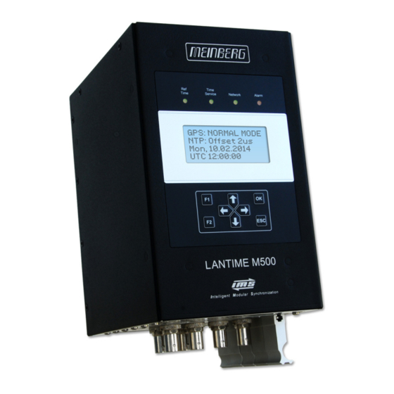
- Page 3 Front view (Frontansicht) LANTIME IMS-M500...
- Page 4 Bottom view (Ansicht Unterseite) LANTIME IMS-M500...
-
Page 5: Table Of Contents
Table of Contents 1 Imprint 2 Safety instructions for building-in equipment Additional Safety Hints ......... . . Supply Voltage . - Page 6 12.5.16 CES - Chassis Expansion Slot ........13 Declaration of Conformity Date: 9th June 2016 LANTIME IMS-M500...
-
Page 7: Imprint
1 Imprint 1 Imprint Meinberg Funkuhren GmbH & Co. KG Lange Wand 9, 31812 Bad Pyrmont - Germany Phone: + 49 (0) 52 81 / 93 09 - 0 Fax: + 49 (0) 52 81 / 93 09 - 30 Internet:http://www.meinberg.de... -
Page 8: Safety Instructions For Building-In Equipment
• Assembling and disassembling of the power connector is only allowed if the device is disconnected from power supply (e.g. trough primary side line protection). • All feed lines are sufficiently protected and dimensioned. Fuse: T2.5A Connector Diameter: - 2,5mm / 17AWG - 13AWG Date: 9th June 2016 LANTIME IMS-M500... -
Page 9: Additional Safety Hints
To ensure safe operation supply mains connected to this decice must be equipped with a fuse and a fault- current circuit breaker according to the applicable national standards for safe operation. The device must be connected to a protective earth with low grounding resistance according to the applicable national rules. LANTIME IMS-M500 Date: 9th June 2016... -
Page 10: Cabling
Do not carry out any installation or maintenance work on the antenna system or cabling when there is a potential risk of lightning. Surge Voltage Protector Due to extremely high currents associated with lightning no surge protection device can provide absolute safety from the impacts caused by lightning! Date: 9th June 2016 LANTIME IMS-M500... -
Page 11: Replacing The Lithium Battery
On the rear panel of the system a grounding connector is provided. Note: Use a grounding cable with >= 1,5mm Please ensure a correct crimp connection! LANTIME IMS-M500 Date: 9th June 2016... -
Page 12: Quick Start
NOTE: These settings are related to the first Ethernet connection (ETH0). After this all further settings can be done via network interface, either by using a WEB browser or a Telnet Session. Default user: root Default password: timeserver Date: 9th June 2016 LANTIME IMS-M500... -
Page 13: The Modular System Lantime
- 3 global IPv6 addresses configurable - Autoconf Feature to be disabled - supported network services: NTP, HTTP, HTTPS, SNMP, SSH - Windows „net time“ via NETBIOS - Winpopup (Window Mail) 4.2 Additional Features • external NTP timeserver LANTIME IMS-M500 Date: 9th June 2016... -
Page 14: User Interface
"bad" clients, which makes the future of the public service questionable. There are already precautions to limit the affect of such clients. Dave Mills, the originator of NTP, cooperates with Date: 9th June 2016 LANTIME IMS-M500... - Page 15 USNO and has already adverted this in the NTP news group. The topics outlined above should provide some arguments to install an own time server, if an accurate time is a requirement for the reliable operation of a local network. LANTIME IMS-M500 Date: 9th June 2016...
-
Page 16: Mounting The Gps Antenna
RG58/CU RG213 10.5mm (1)This specifications are made for antenna/converter units produced after January, 2005 The values are typically ones; the exact ones are to find out from the data sheet of the used cable Date: 9th June 2016 LANTIME IMS-M500... -
Page 17: Antenna Assembly With Surge Voltage Protection
Optional a surge voltage protector for coaxial lines is available. The shield has to be connected to earth as short as possible by using the included mounting bracket. Normally you connect the antenna converter directly with the antenna cable to the system. LANTIME IMS-M500 Date: 9th June 2016... -
Page 18: Antenna Short-Circuit
In case of an antenna line short-circuit the following message appears in the display: If this message appears the clock has to be disconnected from the mains and the defect eliminated. After that the clock can be powered-up again. The antenna supply voltage must be 15V Date: 9th June 2016 LANTIME IMS-M500... -
Page 19: Available Gps / Glonass L1 Antennas
50 meters (H155 - Low-Loss). See data sheet "40 dB GPS L1/GLONASSL1/GALILEO E1 Timing Antenna with Integrated Lightning Pro- tection" (pctel_gpsl1gl.pdf) or download this document: Active GPS/GLONASS Antenna http://www.meinbergglobal.com/download/docs/other/pctel_gpsl1gl.pdf LANTIME IMS-M500 Date: 9th June 2016... -
Page 20: Rv-76G Gps/Glonass Antenne For Mobile Applications
The flat design and the robustness of the case make the RV-76G to one of the most popular antennas on the vehicle navigation and marine market. Figure: RV-76G with Mounting Kit Technical Drawing Date: 9th June 2016 LANTIME IMS-M500... - Page 21 2 MHz Axial ratio 3 dB max. VSWR 2.0 max. Impedance 50 Ohm Environmental Conditions Operating temperature -40 C +85 C Storage temperature -40 C +90 C Relative humidity 95% non-condensing Waterproof 100% waterproof LANTIME IMS-M500 Date: 9th June 2016...
-
Page 22: Booting The Single Board Computer
The NTPD tries to keep the offset below +-128 ms; if the offset becomes too large, the system time is set with the receiver’s time. Typically values for the offset are +-5 ms after the NTPD has already synchronized. Date: 9th June 2016 LANTIME IMS-M500... -
Page 23: Configuration User Interface
To set up a HTTP connection the following address is to enter in a web browser: http://198.168.10.10 // LANTIME IP address password: timeserver To set up a Secure HTTP (HTTPS) connection the following address is entered in a web browser: https://198.168.10.10 // LANTIME IP address password: timeserver LANTIME IMS-M500 Date: 9th June 2016... -
Page 24: The Menues In Detail
Parameter / Check Network Linkup“) is not connected „Alarm“ off: no error at moment red: general error – more information will be shown on display. When pressing „F1“ from main menu a short description for menu navigation will be displayed: Date: 9th June 2016 LANTIME IMS-M500... - Page 25 Local Strat. Network Restart NTP System PTP IEEE1588 Ref. Time -> Interfaces <- Time Service Global Cfg. ->Network <- Services System Ref. Time > Time Zone < Time Service Restart Network Factory Reset ->System <- LANTIME IMS-M500 Date: 9th June 2016...
-
Page 26: The Graphical User Interfaces
Connect to the web interface by entering the following address into the address field of your web browser: http://198.168.10.10 (You need to replace 198.168.10.10 with the IP address of your LANTIME). Default Login User: root Password: timeserver Date: 9th June 2016 LANTIME IMS-M500... -
Page 27: The Web Interface
Network information - first interface Receiver status NTP status Last messages By using the navigation on top of the page you can reach a number of configuration menus, which are described in the next chapters. LANTIME IMS-M500 Date: 9th June 2016... -
Page 28: Attachment: Technical Information
3: GND (Ground) 4: not connected 100-240 V 5: VCC + 100-240 V / 50-60Hz Variant: 19-72VDC 1 2 3 4 5 not connected VCC - GND (Ground) VCC + 19-72 V not connected Date: 9th June 2016 LANTIME IMS-M500... -
Page 29: Available Modules And Connectors
75 Ohm (Bits) shielded data line 10MHz sine shielded data line Signal Inputs: BNC, RJ45 E1/T1, var. Freq. shielded data line 10MHz, PPS, IRIG, PP shielded data line Chassis Expansion Slot DFK-3 Error Relay LANTIME IMS-M500 Date: 9th June 2016... -
Page 30: Terminal (Console)
• between different LANTIMEs • Keypad locking for secure • using the keypad of the LCD • Transfer of log files • Install Software Updates • Upload and download secure certificates • (SSL, SSH) and passwords Date: 9th June 2016 LANTIME IMS-M500... -
Page 31: Ims Module Options
5pin DFK Hotplug: It is possible to remove or install the power supply out of the terminal equipment during operation. Pin Assignment: 1: N 2: not connected 3: GND (Ground) 4: not connected 5: L LANTIME IMS-M500 Date: 9th June 2016... -
Page 32: Power Supply 20-72 V Dc
Class 1 - regarding EN 60950 Hotplug: It is possible to remove or install the power supply out of the terminal equipment during operation. Pin Assignment: 1: not connected 2: - 3: GND (Ground) 4: + 5: not connected Date: 9th June 2016 LANTIME IMS-M500... -
Page 33: Gps Clock
Nav. Solved: green: positioning successfully Ant. Fail: red: antenna faulty or not connected Fail: red: time has not synchronized Pin Assignment of the DSUB9 Connectors (male): Pin 2: RxD Pin 3: TxD Pin 5: GND LANTIME IMS-M500 Date: 9th June 2016... -
Page 34: Gln Clock
Nav Solved green: positioning successfully Ant Fail red: antenna faulty or not connected Fail red: time has not synchronized Pin Assignment of the DSUB9 Connectors (male): Pin 2: RxD Pin 3: TxD Pin 5: GND Date: 9th June 2016 LANTIME IMS-M500... -
Page 35: Lan-Cpu
10/100 Base-T with RJ45-Jack State LEDs: LAN 0 Interface LED - Connect, Activity and Speed of the network connection LAN-CPU R - Reference Time T - Time Service N - Network A - Alarm LANTIME IMS-M500 Date: 9th June 2016... -
Page 36: Reference Input Modules (Mri, Esi)
LED B: green, if 10 MHz or PPS or both signals are available at the same time Figure right:MRI - standard input signals via BNC female connectors Power Requirements: 5 V +-5%, 50 mA Date: 9th June 2016 LANTIME IMS-M500... - Page 37 LED B green: if Clock and Framed flashing green, if Clock and !Framed flashing yellow, if !Clock and Framed off, if !Clock and !Framed Figure right: ESI - telecom signal inputs via BNC female and RJ45 connectors LANTIME IMS-M500 Date: 9th June 2016...
-
Page 38: Cpe And Bpe Output Modules (Frontend - Backend)
BPE) or for autonomously generating a wide range of different signals by using a microprocessor (on a CPE). The front-end makes a selection of the signals available on physical connectors. CPE - Backend BPE - Backend Date: 9th June 2016 LANTIME IMS-M500... - Page 39 3 and output 4 Figure right: BPE Frontend BPE-1000 Standard outputs - BNC female: PPS, 10MHz, TC DCLS and TC AM BPE 5000 Fiber Optic ST-Connectors PPS, 10MHz, TC DCLS und TC AM LANTIME IMS-M500 Date: 9th June 2016...
- Page 40 Out 1 - Out 4: TC DCLS BPE-2050 4 x BNC female Out 1 - Out 3: TC DCLS Out 4: TC AM BPE-2080 4 x BNC female Out 1 - Out 4: 2.048kHz Date: 9th June 2016 LANTIME IMS-M500...
- Page 41 Figure: CPE Frontends CPE-1000: 4 config. outputs via BNC female CPE-5000: 4 config. outputs / FO - ST connectors CPE-2500: 3 x prog. Pulses (DFK-2) / 1 x TC AM (BNC) LANTIME IMS-M500 Date: 9th June 2016...
- Page 42 TxD + / RxD + TxD - TxD - / RxD - D-SUB 9 Male TxD + PPO + TxD + / RxD+ PPO + TxD - PPO - TxD - / RxD - PPO - Date: 9th June 2016 LANTIME IMS-M500...
-
Page 43: Lne-Gbe: Network Expansion With Gigabit Support
In a factory assembling, LNE modules are sorted in an ascending order starting from left to right (see the corresponding figure above). LAN 0 is therefore always the first network interface of the LAN-CPU. LANTIME IMS-M500 Date: 9th June 2016... -
Page 44: Hps-100: Ptp / Synce / Hardware Ntp Interface
/ 32768 Multicast Hybrid Transactions HPS-100 [512]: up to 512 Clients / 65536 Multicast Hybrid Transactions HPS-100 [1024]: up to 1024 Clients / 131072 Multicast Hybrid Transactions HPS-100 [2048]: up to 2048 Clients / 262144 Multicast Hybrid Transactions Date: 9th June 2016 LANTIME IMS-M500... - Page 45 Passiv Mode off - yellow uncalibrated red - red stopped A detailed configuration guide you will find in the corresponding firmware manual of the system. See chapter "The Web Interface -> Configuration: PTP V2". LANTIME IMS-M500 Date: 9th June 2016...
-
Page 46: Tsu V3: Ieee-1588 Time Stamp Unit
LED A - LED B: Shows the current State of the TSU yellow - yellow Listening green - off Master Mode off - green Slave Mode yellow - off Passiv Mode off - yellow uncalibrated red - red stopped Date: 9th June 2016 LANTIME IMS-M500... -
Page 47: Liu - Line Interface Unit
Power T1 E1 Power: Init blue during initialisation, green in normal operation mode green selected mode T1 red: output disabled yellow: signal quality unknown green selected mode E1 red: output disabled yellow: signal quality unknown LANTIME IMS-M500 Date: 9th June 2016... - Page 48 IMS-LIU Telecom Output Signals The board LIU (Line Interface Unit) was designed to convert the GPS-locked standard frequency of a precon- nected Meinberg satellite controlled clock (GPS and GLONASS) into several timing signals that can be used for various synchronization or measurement tasks.
- Page 49 G703-13, balanced isolation 1544 kHz or 2048 kHz isolation micro controller amplifier amplifier clock outputs G703-13, unbalanced amplifier 1544 kHz or 2048 kHz framer & low pass filter 4.096 MHz line interface amplifier LANTIME IMS-M500 Date: 9th June 2016...
- Page 50 BNC connectors or balanced via RJ45 connectors. Two different line codes used for error correction are known for the transmission of framed signals. The board LIU generates B8ZS- (in T1-mode) or HDB3-coded (in E1-mode) output signals by standard. Date: 9th June 2016 LANTIME IMS-M500...
- Page 51 12 Attachment: Technical Information Pulse templates The following pulse templates are required by ANSI (T1-mode) and CCITT (E1-mode) for output signals in telecom applications. The board LIU meets these recommendations. T1 (T.403): E1 (G.703): LANTIME IMS-M500 Date: 9th June 2016...
- Page 52 4 x BNC Clock (0/4) 4 x BNC LIU-A0044 Clock (4/0) 4 x RJ45 Clock (0/4) 4 x BNC LIU-A2222 BITS (2/2) 2 x RJ45, 2 x BNC Clock (2/2) 2 x RJ45, 2 x BNC Date: 9th June 2016 LANTIME IMS-M500...
- Page 53 T1 E1 LIU-A4000 LIU-A0040 LIU-A0004 LIU-A2020 LIU-A2002 LIU_A0202 LIU_A0400 LIU-A1111 BITS (4/0) Clock (4/0) Clock (0/4) BITS (2/0) BITS (2/0) BITS (0/2) BITS (0/4) BITS (1/1) Clock (2/0) Clock (0/2) Clock (0/2) Clock (1/1) LANTIME IMS-M500 Date: 9th June 2016...
-
Page 54: Lno - 10Mhz Sinus Output Module
OCXO in warm up phase 10MHz reference not available Quality of the reference signal is not sufficient All LEDs green: Normal operation, outputs activated Associated LED red: defect output or short circuit during normal operation Date: 9th June 2016 LANTIME IMS-M500... -
Page 55: Fdm - Frequency Deviation Monitoring
/ not sync. yellow signal not available green blinking Timesync green Accurate LED A: green FD (Frequency Deviation) within the configured limits FD Overflow LED B: green TD (Time Deviation) within the configured limits TD Overflow LANTIME IMS-M500 Date: 9th June 2016... - Page 56 96-pin VG-rail DIN 41612, X1, Power Line In Power supply: +5V DC Current consumption: 0.4 A - 1 A (depending on oscillator type) Ambient temperature: 0 ... 50 C / 32 ... 122 F Humidity: Max. 85% Date: 9th June 2016 LANTIME IMS-M500...
-
Page 57: Scg - Studio Clock Generator
4 x BNC (2.5V TTL into 50 Ohm) outputs with configureable frequencies Input Signal: 10MHz, sinewave or square pulse Current Consumption: 5 V +- 5%, @400 mA Ambient Temperature: 0 ... 50 C / 32 ... 122 F Humidity: 85% max. LANTIME IMS-M500 Date: 9th June 2016... - Page 58 In the "IO Configuration" menu each output frequency can be adjusted seperately. In the figure above the following value is set: Frequency Out 3 = Base Frequency * Scale Frequency Out 3 = 44,1 kHz * 1/4 Frequency Out 3 = 11,025 kHz Date: 9th June 2016 LANTIME IMS-M500...
-
Page 59: Vsg - Video Sync Generator
5 V +- 5%, 250 mA BNC Connectors: 2x BNC female, unbalanced, 300 mV @ 75 2x BNC female, unbalanced, 2.5 V TTL @ 50 Ambient Temperature: 0 ... 55 C Humidity: Max. 85% LANTIME IMS-M500 Date: 9th June 2016... -
Page 60: Ces - Chassis Expansion Slot
Clock 1 Relay B: Clock 2 / PPS Relay C: RSC Switch Unit / 10MHz Technical Specifications: Operational Voltage: Switching Range Relay: 250 V AC / 3 A 220 V DC / 3 A Date: 9th June 2016 LANTIME IMS-M500... -
Page 61: Declaration Of Conformity
13 Declaration of Conformity 13 Declaration of Conformity Konformitätserklärung Doc ID: LANTIME IMS-M500-05032015 Hersteller Meinberg Funkuhren GmbH & Co. KG Manufacturer Lange Wand 9, D-31812 Bad Pyrmont erklärt in alleiniger Verantwortung, dass das Produkt, declares under its sole responsibility, that the product... - Page 62 Date: 9th June 2016 LANTIME IMS-M500...