
Related Manuals for AVE Domoalarm AF922RF


Summary of Contents for AVE Domoalarm AF922RF
- Page 1 Domoalarm Centrale radio filo Dual band Radio hard-wired control panel Dual band Cod. AF922RF Centrale radio Dual band Radio control panel Dual band Cod. AF923RS C0490 03 01-02-08...
- Page 2 1999/44/CE, art. 1519 C.C.). Il difetto deve essere denunciato entro due mesi dalla data della scoperta dello stesso. I cinque anni si intendono dal momento della consegna del prodotto da parte di AVE. • I prodotti AVE sono prodotti da installazione.
-
Page 3: Table Of Contents
Centrale radio filo Dual band AF922RF .................. 6 INTRODUZIONE ........................6 CARATTERISTICHE TECNICHE.................... 6 Conformità normativa ......................6 ARCHITETTURA E COMPONENTI DEL SISTEMA ............... 7 ALIMENTATORE ........................7 DESCRIZIONE DEL FUNZIONAMENTO................8 Scelta della configurazione di sistema................. 8 Inserimento disinserimento e parzializzazione ..............8 Comportamento del sistema in stato di allarme.............. - Page 4 IMPOSTAZIONI ........................37 VISTA INTERNA DELLA CENTRALE .................. 38 SOSTITUZIONE DELLA BATTERIA ..................38 Radio hard-wired control panel Dual band AF922RF............39 INTRODUCTION ........................39 TECHNICAL DATA ....................... 39 Standard Compliance ......................39 SYSTEM ARCHITECTURE AND COMPONENTS ............... 40 POWER SUPPLY UNIT......................41 OPERATION .........................
- Page 5 OPERATION ......................... 65 Choice of the system configuration..................65 Activation, disactivation and partial activation..............66 Behaviour of the system in alarm status ................66 Event history file ........................ 69 Test function ........................69 PROGRAMMING........................69 Menu Hierarchy........................70 PROGRAMMING OF THE SYSTEM PERIPHERAL DEVICES ( EXTRAS MENU ) ..... 70 SETTINGS..........................
-
Page 6: Centrale Radio Filo Dual Band Af922Rf
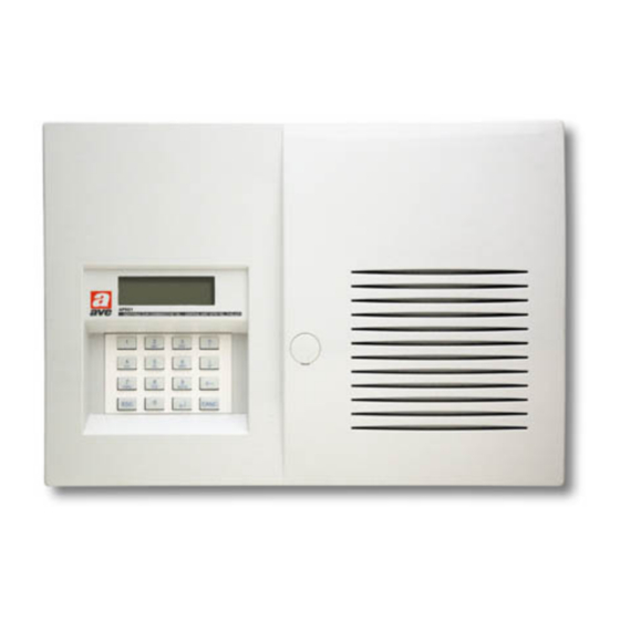
Centrale radio filo Dual band AF922RF INTRODUZIONE Frutto delle più recenti ed innovative ricerche AF922RF è un dispositivo che può gestire fino a 99 rivelatori radio più 6 ingressi via filo, singolarmente identificabili tramite la funzione “etichetta” che, opportunamente programmata, riporta sul display il punto di provenienza dell’allarme (es: salone, cucina, corridoio, ecc). -
Page 7: Architettura E Componenti Del Sistema
ARCHITETTURA E COMPONENTI DEL SISTEMA ALIMENTATORE L’alimentatore interno alla centrale eroga una tensione di 13Vcc e una corrente di 950mA con protezione a 700mA, per agevolare il calcolo dell’assorbimento totale ai fini dell'autonomia in assenza rete, è fornita la seguente tabella: Codice Descrizione Assorbimento (mA) Quantità... -
Page 8: Descrizione Del Funzionamento
* Assorbimento in stato normale, con retroilluminazione accesa (JP2 Inserito) +70mA Nota: per garantire un’autonomia, in assenza di rete, all’impianto pari a 24h è opportuno non superare il valore di assorbimento massimo pari a 270mA (con batterie da 12V 6,5Ah). DESCRIZIONE DEL FUNZIONAMENTO Scelta della configurazione di sistema AF922RFpermette di realizzare due differenti soluzioni impiantistiche di protezione:... -
Page 9: Comportamento Del Sistema In Stato Di Allarme
Comportamento del sistema in stato di allarme Sistema disinserito In caso di manomissione della centrale, dei rivelatori o delle tastiere: Manomissione 24h segnalazione acustica a bassa intensità del buzzer della centrale per 3 minuti • In caso di allarme tecnico: Allarme tecnico 24h segnalazione acustica a bassa intensità... - Page 10 Nota: Tutte le altre segnalazioni sono uguali al funzionamento del sistema disinserito, vedi tabella precedente. Sistema inserito totalmente In questa condizione la centrale presenta differenze di funzionamento secondo la configurazione di sistema scelta ( Tradizionale o Pre-Allarme, vedi “ Scelta della configurazione di sistema “) e la conseguente programmazione effettuata in fase di installazione.
-
Page 11: Memoria Eventi
Memoria eventi La centrale memorizza fino a 200 eventi (inserimento, disinserimento e allarmi vari) visualizzando la data, l'ora e la periferica interessata. E' possibile visualizzare tali eventi digitando il codice utente o il codice installatore seguito da ↓ , verrà visualizzato l'evento più... -
Page 12: Tastiera Di Programmazione
TASTIERA DI PROGRAMMAZIONE Tutte le fasi di programmazione vengono svolte utilizzando la tastiera e il display del combinatore. I tasti hanno il seguente significato. Tasti Funzionamento normale Funzionamento in scrittura 0 ÷ ÷ ÷ ÷ 9 ( punto ) Impostazione numeri e scrittura ( spazio ) Scorrimento menù... -
Page 13: Gerarchia Menù
GERARCHIA MENÙ Per entrare nel menu digitare il codice seguito dal tasto (vedi nota 1) Impostazioni Strumenti ↑↓ Tasti scorrimento - Telecomandi - Escl. sensori Tasto conferma - Codici - Escl. Filari - Zona Allarme A - Impostaz. rele Per uscire - Zona Allarme B - Mancanza rete... -
Page 14: Af978R Tastiera Per Inserimento Disinserimento E Parzializzazione Del Sistema
AF978R Tastiera per inserimento disinserimento e parzializzazione del sistema La tastiera AF978R, riportata in figura, presenta le seguenti caratteristiche tecniche: Alimentazione: pila a litio 3,6V-2,2 Ah. Tipo SB AA 11 stilo (cod. AVE AF916); • Assorbimento: 5mA a riposo – 40mA in trasmissione;... -
Page 15: Af940R Telecomando Per Inserimento Disinserimento E Parzializzazione Del Sistema
AF940R Telecomando per inserimento disinserimento e parzializzazione del sistema Il telecomando AF940R, riportato in figura, presenta le seguenti caratteristiche tecniche: P2 Pulsante grigio/rosso Alimentazione: due pile al Litio 3V tipo CR2016 • P1 Pulsante rosso Assorbimento: 20mA in trasmissione • Autonomia: 6 mesi minimo (in funzione del numero di manovre) •... -
Page 16: Af968R E Af968R-Db Rivelatori Ir-P
Selezionare il menù STRUMENTI seguito da ; • Selezionare il menù 24H RAPINA oppure 24H PANICO seguito da ; • Sul display apparirà SENSORE confermare con ; • Sul display apparirà PREMI TASTO 10s, premere il pulsante nero del telecomando per 10s. •... - Page 17 Allarme per pila scarica. La necessità di sostituzione della pila è segnalata da 3 ”beep”, emessi dal rivelatore congiuntamente alla segnalazione di allarme oltre un mese prima della scarica totale. La centrale AF922RF permette di memorizzare fino a 99 codici radio provenienti dai rivelatori della gamma ave. Per la programmazione procedere come segue: Selezionare il menù...
-
Page 18: Af913R E Af913R-Db Rivelatori Perimetrali Multifunzioni
Terminata la programmazione premere ESC; • Nota: l'etichetta di ogni rivelatore viene memorizzata nella memoria eventi ad ogni allarme. Nota: La centrale emette un beep di conferma, tre beep se la procedura non è andata a buon fine. La centrale AF922RF permette di eliminare singolarmente uno dei rivelatori memorizzati. Per la eliminazione procedere come segue: Selezionare il menù... - Page 19 allarme con contaimpulsi (per collegamento esterno di rivelatori inerziali) • allarme tecnico (per collegamento esterno di rivelatori tecnici) • Invio segnale di presenza (supervisione) e di batteria scarica ogni 22 minuti • Caratteristiche R.F.: trasmissione radio digitale a doppia frequenza (DUAL BAND) gestita da •...
- Page 20 IMPIEGO PREDISPOSIZIONE Fissare il magnete (in dotazione) sulla porta o finestra da proteggere, ed il rivelatore AF913R sull’infisso. Selezionare se desiderata la funzione di fine allarme tramite il dipwitch 3: ON = fine allarme abilitato OFF = fine allarme disabilitato Protezione Può...
-
Page 21: Af969R E Af969R-Db Rivelatori Ir-P Per Esterno
AF969R e AF969R-DB rivelatori IR-P per esterno AF969R e AF969R-DB sono rivelatori IR-P realizzati per poter essere installati sia all’interno sia all’esterno di un’abitazione. Grazie alla lente “a tenda” è possibile effettuare una protezione di tipo perimetrale. Come indicato nell’esempi d’installazione, il rivelatore può essere installato, con gli opportuni accorgimenti, per proteggere il perimetro esterno di un’abitazione. -
Page 22: Af942R Indicatore Remoto Di Stato Impianto
AF942R Indicatore remoto di stato impianto L’indicatore remoto di stato AF942R, riportato in figura, presenta le seguenti caratteristiche che: Alimentazione: da 8 a 24 V c.c. o c.a. 50Hz • Assorbimento: 5mA a riposo, 18mA con led accesi • Contenitore: ABS Bianco (44 x 67 x 19) mm •... - Page 23 COLORE ACCESO SPENTO LAMPEGGIANTE L1 (inserito) Verde Centrale inserita Centrale disinserita L2 (allarme) Rosso Non in allarme Allarme L3 (alimentazione) Verde Alimentazione presente Alimentazione assente L'indicatore di stato impianto, necessitando di una tensione di alimentazione compresa tra 8 e 24V c.c. o c.a. 50Hz, può...
-
Page 24: Af53901R Sirena Via Radio Autoalimentata Per Esterni
AF53901R Sirena via radio autoalimentata per esterni La sirena AF53901R, riportata in figura, presenta le seguenti caratteristiche tecniche: Alimentazione: fornita esclusivamente da batteria al litio da 7,2V-13Ah (in dotazione). • Assorbimento: a riposo 100 µA max 7,2 V, in allarme: 2 A max 7,2V •... -
Page 25: Af53901R Sirena Via Radio Autoalimentata Per Esterni Di Seconda Generazione
che andrà a premere il pistoncino (color ottone) e quindi chiudere il contatto come mostrato in figura. NOTA: La necessità della sostituzione della batteria è segnalata con una serie di beep, della durata di 30s, emessa all'atto dell'inserimento e del disinserimento del sistema. AF53901R Sirena via radio autoalimentata per esterni di seconda generazione La sirena di seconda generazione differisce da quella sopra riportata per le seguenti caratteristiche : Il contatto antiasportazione è... -
Page 26: Impostazioni
centrale. L’avvenuta programmazione è segnalata dalla sirena con una serie di 6 BEEP e relativi lampeggi Per quanto riguarda la procedura per eliminare il codice radio è uguale a quella del rivelatore AF968R e AF968R- IMPOSTAZIONI Esclusione Sensori Selezionare il menù IMPOSTAZIONI seguito da ; •... -
Page 27: Modifica Del Codice Installatore
Modifica del codice installatore Con questa funzione è possibile modificare il codice installatore impostato all’atto dell’accensione. Procedere nel seguente modo per modificarlo: Selezionare il menù IMPOSTAZIONI seguito da • Selezionare CODICE INSTALL seguito da • Seguire le indicazioni riportate sul display •... -
Page 28: Vista Interna Della Centrale
VISTA INTERNA DELLA CENTRALE JP2 Inserito: Retro illuminazione Manuale ON. JP2 Disinserito: Retro illuminazione Automatica. SOSTITUZIONE DELLA BATTERIA Per la sostituzione della batteria procedere come segue: Mettere in test la centrale digitando il codice seguito da ↑ • Aprire il contenitore svitando la vite di chiusura posta sotto l’apposito tappo •... -
Page 29: Descrizione Morsettiera
DESCRIZIONE MORSETTIERA Uscita allarme panico. Collettore aperto, chiude Ingresso tamper zona B TMPB verso il negativo 100mA/30Vcc Uscita allarme rapina. Collettore aperto, chiude Ingresso d’allarme via filo B2 verso il negativo 100mA/30Vcc Uscita allarme tecnologico. Collettore aperto, Ingresso d’allarme via filo B1 chiude verso il negativo 100mA/30Vcc Uscita allarme anomalia RF. -
Page 30: Schema Di Collegamento
SCHEMA DI COLLEGAMENTO AF53900 SIRENA IR-P AF962 IR-P AF962 CANC IR-P AF962 IN 3... -
Page 31: Centrale Radio Dual Band Af923Rs
Centrale radio Dual band AF923RS INTRODUZIONE Frutto delle più recenti ed innovative ricerche AF923RS è un dispositivo che può gestire fino a 99 rivelatori radio singolarmente identificabili tramite la funzione “etichetta” che, opportunamente programmata, riporta sul display il punto di provenienza dell’allarme (es: salone, cucina, corridoio, ecc). CARATTERISTICHE TECNICHE Alimentazione da batteria alcalina 9 V –... -
Page 32: Architettura E Componenti Del Sistema
ARCHITETTURA E COMPONENTI DEL SISTEMA... -
Page 33: Descrizione Del Funzionamento
DESCRIZIONE DEL FUNZIONAMENTO Scelta della configurazione di sistema AF923RS permette di realizzare due differenti soluzioni impiantistiche di protezione: sistema di allarme tradizionale. Programmando le zone (A-B-C) in questo modo all’atto della rivelazione • dell’intruso si avrà l’allarme generale. sistema di pre-allarme. Si realizza programmando una zona (A-B-C) come “esterna”. I rivelatori a questa •... -
Page 34: Comportamento Del Sistema In Stato Di Allarme
Sistema inserito parzialmente In questa condizione la centrale presenta differenze di funzionamento secondo la configurazione di sistema scelta ( Tradizionale o Pre-Allarme, vedi “ Scelta della configurazione di sistema “) e la conseguente programmazione effettuata in fase di installazione. Eventuali rivelatori programmati con ritardo di intervento provocheranno gli allarmi dopo il ritardo impostato, durante questo tempo si avrà... - Page 35 Sistema inserito totalmente In questa condizione la centrale presenta differenze di funzionamento secondo la configurazione di sistema scelta ( Tradizionale o Pre-Allarme, vedi “ Scelta della configurazione di sistema “) e la conseguente programmazione effettuata in fase di installazione. Eventuali rivelatori programmati con ritardo di intervento provocheranno gli allarmi dopo il ritardo impostato, durante questo tempo si avrà...
-
Page 36: Memoria Eventi
Memoria eventi La centrale memorizza fino a 200 eventi (inserimento, disinserimento e allarmi vari) visualizzando la data, l'ora e la periferica interessata. E' possibile visualizzare tali eventi digitando il codice utente o il codice installatore seguito da ↓ , verrà visualizzato l'evento più... -
Page 37: Gerarchia Menù
GERARCHIA MENÙ Per entrare nel menu digitare il codice seguito dal tasto (vedi nota 1) Impostazioni Strumenti ↑↓ Tasti scorrimento Tasto conferma - Telecomandi - Esclusione sensori - Codici - Orologio/Data Per uscire - Zona Allarme A - Codice installatore - Zona Allarme B - Antiscanner - Zona Allarme C... -
Page 38: Vista Interna Della Centrale
VISTA INTERNA DELLA CENTRALE ALLOGGIAMENTO BATTERIA JP2 Inserito: Retro illuminazione Manuale ON. JP2 Disinserito: Retro illuminazione Automatica. SOSTITUZIONE DELLA BATTERIA Per la sostituzione della batteria procedere come segue: Mettere in test la centrale digitando il codice seguito da ↑ • Aprire il contenitore svitando la vite di chiusura posta sotto l’apposito tappo •... -
Page 39: Radio Hard-Wired Control Panel Dual Band Af922Rf
Radio hard-wired control panel Dual band AF922RF INTRODUCTION Resulted from the latest and most innovative researches, AF922RF is able to control up to 99 radio detectors and 6 hard-wired input, that can be identified individually, even through the “label” function that, if duly programmed, displays where the alarm comes from (ex: hall, kitchen, corridor, etc..). -
Page 40: System Architecture And Components
SYSTEM ARCHITECTURE AND COMPONENTS... -
Page 41: Power Supply Unit
POWER SUPPLY UNIT The power supply unit inside the control panel supplies a 13Vdc voltage and a 850mA current. The following table is supplied to facilitate the calculation of the system’s total current consumption for its operation in the event of a power failure: Description Consumption (mA) Quantity... -
Page 42: Activation, Disactivation And Partial Activation
Activation, disactivation and partial activation AF922RF AF940R AF978R Press the red button Insert user code Insert the code and press the red button Full activation followed confirm Press the red-black button Insert user code Insert the user code, select followed by ESC, select the the zones to be excluded Note: Only zones A and B are... -
Page 43: Behaviour Of The System In Alarm Status
Partially activated System In this condition the control panel has different operations according to the chosen system configuration ( Traditional or Pre-Alarm, refer to Choice of the system configuration ) and programming performed upon installation. Any detectors programmed with a delay, will create the alarms once the preset delay is elapsed, during this time the control panel buzzer will emit an acoustic signal ( beep-beep-beep ). - Page 44 Fully activated System In this condition the control panel has different operations according to the chosen system configuration ( Traditional or Pre-Alarm, refer to Choice of the system configuration ) and programming performed upon installation. Any detectors programmed with a delay, will create the alarms once the preset delay is elapsed, during this time the control panel buzzer will emit an acoustic signal ( beep-beep-beep ).
-
Page 45: Event History File
Event history file The control panel stores up to 200 events (switched-on, switched-off and different alarms) by displaying the date, time and the peripheral devices involved. These events can be displayed by inserting the user code or the installer code followed by ↓, the latest event will be displayed. -
Page 46: Keyboard Programming
KEYBOARD PROGRAMMING All are of the programming phase are carried out using the keyboard and the display. The keys have the following meaning. Keys Normal Operation Writing operation 0 ÷ ÷ ÷ ÷ 9 ( point ) Dialling and writing sms ( space ) Menu sliding and parameters Cancellation last character... -
Page 47: Menu Hierarchy
MENU HIERARCHY Access from the menu with code (see note 1) Settings Extras - Exclusion Sensors - Remote controls - Excl. wired inp. - Keyboard Codes ↑↓ Scroll keys - Relay settings - Alarm Group A - Mains failure - Alarm Group B ... -
Page 48: Af978R Keypad For Activation, Disactivation And Partial Activation Of The System
AF978R Keypad for activation, disactivation and partial activation of the system Keypad AF978R, shown in the picture, has the following technical characteristics: Power supply: Lithium battery 3,6V-2,2 Ah. SB AA 11 (cod. AVE AF916); • Current consumption: 5mA in stand-by – 40mA during transmission;... -
Page 49: Af940R Remote Control For Activation, Disactivation And Partial Activation Of The System
AF940R Remote control for activation, disactivation and partial activation of the system The AF940R remote control shown in the picture has the following technical characteristics: P2 Grey/red pushbutton Power supply: two 3V lithium CR2016-type batteries • P1 Red pushbuttonbutton Current input: 20mA during transmission •... -
Page 50: Af968R & Af968R-Db P-Ir Detectors
Select menu 24H ROBBERY or 24H PANIC followed by ; • SENSOR will be displayed, confirm with ; • PRESS KEY 10 S will be displayed, press the black pushbutton of the remote control for 10s. • The control panel will emit a beep for confirmation. It will emit three beeps if the procedure has not been •... - Page 51 • the battery needs to be replaced one month before its complete discharge. The AF922RF control panel allows to store up to 99 radio codes coming form the AVE detectors. For programming, proceed as follows: Select menu EXTRAS followed by ;...
-
Page 52: Af913R & Af913Db Multifunction Perimeter Detectors
AF913R & AF913DB multifunction perimeter detectors Connection External for external magnet llegamento contact Reed External detector Dipswitches contact contact (by wire) Pulse count Magnet detector distance dipswitches max 5mm 1-2: pulse count 3: end of alarm 4: shock 5: antiremoval exclusion (ON=exclude 6: NC input exclusion (ON=excluded) The AF913R &... - Page 53 the alarm will be transmitted to the control panel provided that micro-switch 3 is in ON position. An internal anti-shock device is provided: it consists of a piezoelectric device that, in the case of a violent shock, produces an alarm that is transmitted to the control panel. This function can be cancelled by means of micro-switch 4.
-
Page 54: Af969R And Af969R-Db Pir Detector For Internal / External Use
changed, the programming sequence of the detector must be repeated. Programming of dipswitches 1, 2 and 4 can be changed without repeating programming. Note: in order to use the multi-function perimeter detector to connect a detector for technical alarms to the control panel by radio, the detector must be programmed on the 24H TECH ALARMS channel To delete the detector, follows the same procedure as detector AF968R. - Page 55 For programming, proceed as follows: Turn on the power to the system: the LED L3 (green) will switch on. • Press the internal reset push-button; LED L1 (green) and L2 (red) will switch on alternatively: the code • learning sequence is carried out. Transmit the signal of “disactivated”...
-
Page 56: Af53901R Outdoor Self-Powered Wireless Sounder
As an alternative, the system can be powered using the voltage with the above characteristics. NOTE: the system does not work if there is no power but it maintains the state it had before power cut and it restores it upon repowering. AF53901R Outdoor self-powered wireless sounder The AF53901R siren shown in the picture, has the following technical characteristics: Power: supplied only by 7.2V-13Ah (supplied with the equipment). -
Page 57: Af53901R Outdoor Self-Powered Wireless Second Generation Sounder
To perform the anti-removal protection, it is necessary to keep closed the anti-removal contact seated on the rear side of the sounder by fixing a screw in the wall (in the position shown by the drilling jig) and leaving it project by 8 mm that will press the pin (brass coloured) and therefore close the contact as shown in the figure Note: A series of beeps produced for 30 seconds when activating and disactivating the system... -
Page 58: Settings
signal, on any free channel. Connect the battery, the control unit confirms the programming with an acoustic signal (beep). Receiving area programming: close the siren completely, an acoustic signal will confirm with a beep. The • siren is programmed automatically the first time the control unit is switched OFF. The completed programming is confirmed by the siren with a series of 6 beeps and flashing light. -
Page 59: User Code Change
Select menu SETTINGS followed by ; • Select TIME AND DATE followed by ; • Follow the instructions displayed on the display • User code change By this function the user code set upon switch-on, can be changed. Proceed as follows to change it: Select menu SETTINGS followed by ;... -
Page 60: Internal View Of The Control Panel
Proceed as follows: Select menu SETTINGS followed by ; • Select SYSTEM RESET followed by ; • Follow the instructions displayed on the display • INTERNAL VIEW OF THE CONTROL PANEL BATTERY REPLACAMENT To replace the battery, proceed as follows: Set the control panel to test mode by inserting the code followed by ↑... -
Page 61: Terminal Board Description
TERMINAL BOARD DESCRIPTION Panic alarm output. Open collector, close on Tamper input - B area TMPB GND 100mA/30Vcc Rubbery alarm output. Open collector, close on Wired input alarm – B2 area GND 100mA/30Vcc Technological alarm output. Open collector, close Wired input alarm – B1 area on GND 100mA/30Vcc RF anomaly output. -
Page 62: Wiring Diagram
WIRING DIAGRAM AF53900 SOUNDER BUGLE BUGLE BLINKING LIGHT BLINKING LIGHT POWER SUPPLY + POWER SUPPLY - TAMPER MICROSWITCH TAMPER MICROSWITCH SOUNDER CONTROL FLASH CONTROL FLASH THREAD INTERRUPTED SIGNAL IR-P AF962 IR-P AF962 CANC IR-P AF962 Load 1N4007 AVE 45369 IN 3... -
Page 63: Radio Control Panel Dual Band Af923Rs
Radio control panel Dual band AF923RS INTRODUCTION Resulted from the latest and most innovative researches, AF923RS is able to control up to 99 radio detectors that can be identified individually even through the “label” function that, if duly programmed, displays where the alarm comes from (ex: hall, kitchen, corridor, etc..). -
Page 64: System Architecture And Components
SYSTEM ARCHITECTURE AND COMPONENTS... -
Page 65: Operation
OPERATION Choice of the system configuration AF923RS allows to have two different system protection solutions: traditional alarm system. By programming the zones (A-B-C) in this way, the general alarm will be • activated upon detection of the intruder. pre-alarm system. It is obtained by programming a zone (A-B-C) as an “external” zone. The detectors •... -
Page 66: Activation, Disactivation And Partial Activation
Activation, disactivation and partial activation AF923RS AF940R AF978R Press the red button Insert user code Insert the code and press Full activation the red button followed confirm Press the red-black button Insert user code Insert the user code, select followed by ESC, select the the zones to be excluded Note: Only zones A and B are by pressing A, B, C... - Page 67 Partially activated System In this condition the control panel has different operations according to the chosen system configuration ( Traditional or Pre-Alarm, refer to Choice of the system configuration ) and programming performed upon installation. Any detectors programmed with a delay, will create the alarms once the preset delay is elapsed, during this time the control panel buzzer will emit an acoustic signal ( beep-beep-beep ).
- Page 68 Fully activated System In this condition the control panel has different operations according to the chosen system configuration ( Traditional or Pre-Alarm, refer to Choice of the system configuration ) and programming performed upon installation. Any detectors programmed with a delay, will create the alarms once the preset delay is elapsed, during this time the control panel buzzer will emit an acoustic signal ( beep-beep-beep ).
-
Page 69: Event History File
Event history file The control panel stores up to 200 events (switched-on, switched-off and different alarms) by displaying the date, time and the peripheral devices involved. These events can be displayed by inserting the user code or the installer code followed by ↓, the latest event will be displayed. -
Page 70: Menu Hierarchy
MENU HIERARCHY Access from the menu with code (see note 1) Settings Extras - Excl. Sensors - Remote controls - Time and date - Keyboard Codes ↑↓ Scroll keys - Installer code - Alarm Group A - antiscanner - Alarm Group B ... -
Page 71: Internal View Of The Control Panel
INTERNAL VIEW OF THE CONTROL PANEL JP2 connected: display light manual ON. JP2 disconnected: display light automatic ON. BATTERY REPLACAMENT To replace the battery, proceed as follows: Set the control panel to test mode by inserting the code followed by ↑ •...