Trane Horizon OAKD Series Installation, Operation And Maintenance Manual
Outdoor air unit, indirect fired gas/electric heat/air source heat pump
Hide thumbs
Also See for Horizon OAKD Series:
- Installation, operation and maintenance manual (128 pages)
Table of Contents
Advertisement
Installation, Operation,
and Maintenance
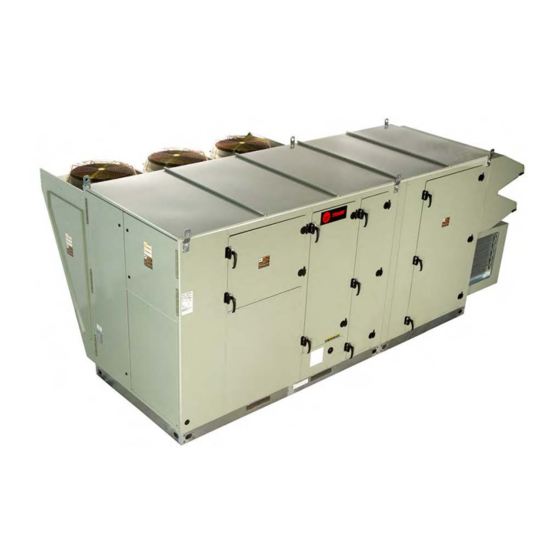
Horizon™ Outdoor Air Unit
Indirect Fired Gas/Electric Heat/Air Source Heat Pump
Models: OAKD, OAKE/F, OAND, OANE/F
Important:
Proper execution of the tasks outlined in this Installation, Operation, and Maintenance manual
require and assume the technician has been certified as a start up technician for the Horizon Outdoor
Air unit. This includes working knowledge of the Tracer TU program.
Only qualified personnel should install and service the equipment. The installation, starting up, and servicing
of heating, ventilating, and air-conditioning equipment can be hazardous and requires specific knowledge and
training. Improperly installed, adjusted or altered equipment by an unqualified person could result in death or
serious injury. When working on the equipment, observe all precautions in the literature and on the tags,
stickers, and labels that are attached to the equipment.
L'installation et l'entretien de cet équipement doivent être assurés exclusivement par du personnel qualifié.
L'installation, la mise en service et l'entretien d'équipements de chauffage, de ventilation et de climatisation
(CVC) présentent un danger et requièrent des connaissances et une formation spécifiques. Une installation,
un réglage ou une modification inappropriés d'un équipement par une personne non qualifiée peut provoquer
des blessures graves, voire la mort. Lors de toute intervention sur l'équipement, respectez les consignes de
sécurité figurant dans la documentation, ainsi que sur les pictogrammes, autocollants et étiquettes apposés
sur l'équipement.
November 2019
SAFETY WARNING
AVERTISSEMENT DE SÉCURITÉ
OAU-SVX01H-EN
Advertisement
Table of Contents
Troubleshooting

Related Manuals for Trane Horizon OAKD Series


Summary of Contents for Trane Horizon OAKD Series
- Page 1 Installation, Operation, and Maintenance Horizon™ Outdoor Air Unit Indirect Fired Gas/Electric Heat/Air Source Heat Pump Models: OAKD, OAKE/F, OAND, OANE/F Important: Proper execution of the tasks outlined in this Installation, Operation, and Maintenance manual require and assume the technician has been certified as a start up technician for the Horizon Outdoor Air unit.
- Page 2 Hydrogen, Chlorine, Fluorine and Carbon (HCFCs). Not all refrigerants containing these compounds have the same potential impact to the environment. Trane advocates the responsible handling of all refrigerants-including industry replacements for CFCs and HCFCs such as saturated or unsaturated HFCs and HCFCs.
- Page 3 Introduction WARNING AVERTISSEMENT Personal Protective Equipment (PPE) Équipements de protection individuelle Required! (EPI) obligatoires ! Failure to wear proper PPE for the job being undertaken En cas d’équipement de protection individuelle could result in death or serious injury. Technicians, in inadapté...
- Page 4 Introduction WARNING AVERTISSEMENT Refrigerant under High Pressure! Risque d’explosion et gaz mortels ! Failure to follow instructions below could result in an Le non-respect de toutes les consignes de manipulation explosion which could result in death or serious injury des fluides frigorigènes peut entraîner la mort ou des or equipment damage.
- Page 5 3. Extinguish any open flame. This document and the information in it are the property of Trane, and may not be used or reproduced in whole or in 4. Immediately call your gas supplier. part without written permission. Trane reserves the right...
-
Page 6: Table Of Contents
Table of Contents Model Number Descriptions Main Electrical Power Requirements ..26 ....8 Horizon Outdoor Air Unit ....8 Condensate Drain Configuration . - Page 7 Table of Contents Microprocessor Control ....65 System Alarms ..... 65 Sensor Failure Alarm Display .
-
Page 8: Model Number Descriptions
Model Number Descriptions Horizon Outdoor Air Unit Digit 1, 2 — Unit Type Digit 11 — Evaporator Type Digit 17 — Indoor Fan Wheel OA = Outdoor Air No Cooling DX 4-Row Interlaced 120.6 Digit 3 — Cabinet Size DX 6-Row Interlaced 140.6 Digit 12 —... - Page 9 Digit 25, 26 — Unit Controls Wheel 125 MBh 28 kW 2 Row/10 FPI 00 = Non-DDC—Electromechanical No Powered Exhaust AA = Trane—Discharge Air Control 150 MBh 32 kW 2 Row/12 FPI w/LON Read-Write w/Display 120.6 200 MBh 40 kW 2 Row/14 FPI AB = Trane—Space Control w/LON...
- Page 10 Model Number Descriptions Digit 32 — ERV Size Digit 37 — Air Flow Monitoring No ERV No Airflow Monitoring 4634 Airflow Monitoring—IFM 5856 Piezo Ring 6488 Airflow Monitoring—PE 6876 Piezo Ring 74122 Airflow Monitoring—Outdoor Air with Display and IFM Digit 33 — Damper Options w/Piezo Ring 100% OA 2-Position Damper Airflow Monitoring—IFM...
-
Page 11: General Information
General Information Overview of Manual receive information from sensors and customer binary contacts to satisfy the applicable request for ventilation, Note: One copy of this document ships inside the control cooling, dehumidification and heating. panel of each unit and is customer property. It must Indoor Fan Failure Input be retained by the unit’s maintenance personnel. -
Page 12: Space Temperature / Rh Sensor (Optional)
General Information of current while calling for cooling and locks the draining internal condensate. External flue to be compressor out. constructed of type 430 stainless steel. On dual circuit units, if the high pressure control opens, Units will be suitable for use with natural gas or Liquid the compressor on the affected circuit is locked out. -
Page 13: Unit Inspection
General Information Unit Inspection • Wash clothes separately from other clothing: rinse washer thoroughly. • Operations such as sawing, blowing, tear-out, and WARNING spraying may generate fiber concentrations requiring additional respiratory protection. Use the appropriate Fiberglass Wool! NIOSH approved respiration in these situations. Product may contain fiberglass wool. -
Page 14: Unit Clearances, Curb Dimensions, And Dimensional Data
Unit Clearances, Curb Dimensions, and Dimensional Data OAK Units WARNING Unit Clearances Combustible Materials! Figure 1. Typical installation clearances for OAK unit Failure to maintain proper clearance between the unit heat exchanger, vent surfaces and combustible materials could cause a fire which could result in death CLEARANCE FROM TOP OF UNIT 72"... - Page 15 Unit Clearances, Curb Dimensions, and Dimensional Data Figure 2. Typical installation clearances for OAK unit Figure 4. Typical installation clearances for OAK unit with auxiliary cabinet with auxiliary cabinet CLEARANCE FROM TOP OF UNIT 72" CLEARANCE " CLEARANCE 48" 6'0" 7'0"...
- Page 16 Unit Clearances, Curb Dimensions, and Dimensional Data Dimensional Data Figure 9. Unit dimensional data for OAK 12–30 tons, horizontal supply and vertical/no return (in.) Figure 7. Unit dimensional data for OAK 12–30 tons, vertical supply and vertical/no return without TOP VIEW 106.21 106.45 43.02...
- Page 17 Unit Clearances, Curb Dimensions, and Dimensional Data Figure 11. Unit dimensional data for OAK 12–30 tons, Figure 10. Unit dimensional data for OAK 12–30 tons, horizontal supply and horizontal return with horizontal supply and horizontal return with ERV (in.) optional exhaust fan (in.) TOP VIEW TOP VIEW 106.21...
-
Page 18: Oan Units
Unit Clearances, Curb Dimensions, and Dimensional Data OAN Units Figure 13. Typical installation clearances for OAN unit Unit Clearances with auxiliary cabinet Figure 12. Typical installation clearances for OANunit Clearance from top of unit 72” Clearance from top of unit 72” Clearance 48”... - Page 19 Unit Clearances, Curb Dimensions, and Dimensional Data Note: Certain options require auxiliary cabinet. Refer to project-specific unit submittals. Figure 15. Typical installation clearances for OAN unit Dimensional Data with auxiliary cabinet Figure 18. Unit dimensional data for OAN30–54 tons, vertical supply and vertical/no return without ERV 6'0"...
- Page 20 Unit Clearances, Curb Dimensions, and Dimensional Data Figure 20. Unit dimensional data for OAN 30–54 tons, Figure 21. Unit dimensional data for OAN 30–54 tons, horizontal supply and vertical/no return (in.) horizontal supply and horizontal return with optional exhaust fan (in.) TOP VIEW 144.17 TOP VIEW...
- Page 21 Unit Clearances, Curb Dimensions, and Dimensional Data Figure 22. Unit dimensional data for OAN 30–54 tons, horizontal supply and horizontal return with ERV (in.) TOP VIEW 144.17 45.87 54.38 15.10 2.88 SA/RA Duct Flange (Typical) FRONT VIEW 98.80 67.47 95.07 92.07 4.97 31.54...
-
Page 22: Unit Weight And Rigging
Unit Weight and Rigging WARNING WARNING Heavy Objects! Improper Unit Lift! Failure to follow instructions below or properly lift unit Failure to properly lift unit could result in unit dropping could result in unit dropping and possibly crushing and possibly crushing operator/technician which could operator/technician which could result in death or result in death or serious injury, and equipment or serious injury, and equipment or property-only damage. - Page 23 Unit Weight and Rigging Table 2. Typical unit weight, center of gravity, and corner weights (percentage of total weight) - air cooled DX units with powered exhaust but without ERV Weight (lb) Center-of-gravity (in.) Corner weight (% of total weight) Length Width Corner A...
-
Page 24: Rigging
Unit Weight and Rigging Figure 24. Rigging and center-of-gravity data Figure 23. Cabinet corners 6-point lift, OAK and OAN cabinets (top view) SPREADER BARS horizontal return, no energy wheel Intake hood Condenser section LIFTING POINTS (6 LOCATIONS) Rigging DETAIL A SCALE 1 : 12 LENGTH WIDTH... -
Page 25: Installation
Installation duct work must be installed and connected to top of roof curb before the unit is set on curb. WARNING If a Curb Accessory Kit is not used: Hazardous Service Procedures! 1. Be sure to use flexible duct connections at the unit. Failure to follow all precautions in this manual and on the tags, stickers, and labels could result in death or 2. -
Page 26: Main Electrical Power Requirements
Installation Main Electrical Power Requirements Assemble and install the roof curb (if applicable). Refer to the latest edition of the curb installers guide that ships with each curb kit. Check curb for level Verify that the power supply complies with the unit installation;... -
Page 27: Chilled Water Connection Size And Location
Installation Figure 26. Condensate trap installation Table 4. Chilled water pipe chase location (in.) Unit PANEL ENCLOSURE D" NPT FEMALE 63.84 19.50 11.00 5.00 CONNECTOR 93.93 20.64 11.00 5.00 Table 5. Chilled water connection size (MPT-in.) Unit Size MPT-in. OAK 12–30 tons OAN 30–54 tons Filter Installation Each unit ships with 2-inch permanent filters (mist... -
Page 28: Main Unit Power
Installation unit’s supply power wiring is properly sized and installed, Figure 30. OAN utility connections refer to the following guidelines. Figure 28. Main power entrance ELECTRICAL DISCONNECT 11.78 MAIN POWER ENTRANCE FOR UNIT CONDENSATE DRAIN 17.74 1.25 IN. NPT 9.76 104.33 THROUGH THE BASE ELECTRIC... -
Page 29: Standard Wiring
Installation Standard Wiring Verify that the condenser and indoor fans turn freely without rubbing and are properly tightened on the shafts. WARNING Check motor mounting bolts and inlet cone for Proper Field Wiring and Grounding tightness. Free spin wheel by hand to check for proper Required! alignment of motor, wheel, and inlet cone. -
Page 30: Electrical Phasing (Three-Phase Motors)
Installation Proper electrical supply phasing can be quickly Volt 1 + Volt 2 + Volt 3 determined and corrected before starting the unit by using AV (Average Voltage) = an instrument such as an Associated Research Model 45 Phase Sequence Indicator and following these steps: V1, V2, V3 = Line Voltage Readings ... -
Page 31: Main Unit Display And Reliatel Controls
Installation temperature during the “Off” cycle to reduce oil foaming during compressor starts. Oil foaming occurs when AVERTISSEMENT refrigerant condenses in the compressor and mixes with Câblage sur site et mise à la terre corrects the oil. In lower ambient conditions, refrigerant migration nécessaires ! to the compressor could increase. -
Page 32: Controls Using 24 Vac
Installation Controls Using 24 Vac Controls Using DC Analog Input/Output (Standard Low Voltage Multiconductor Wire) WARNING Hazardous Voltage! WARNING Failure to disconnect power before servicing could Hazardous Voltage! result in death or serious injury. Disconnect all electric power, including remote disconnects before servicing. Failure to disconnect power before servicing could Follow proper lockout/tagout procedures to ensure the result in death or serious injury. -
Page 33: Dc Conductors
Installation DC Conductors Table 7. Zone sensor module wiring Distance from Unit to Control Recommended Wire Size 000–150 feet 22 gauge 0–45.7 m 0.33 mm 151–240 feet 20 gauge 46–73.1 m 0.50 mm 241–385 feet 18 gauge 73.5–117.3 m 0.75 mm 386–610 feet 16 gauge 117.7–185.9 m... -
Page 34: Pre-Start Check List
8. Startup appointment with Horizon certified Trane service technician set and confirmed. Notes: • Check list must be completed and returned to Trane before startup is scheduled. • Startup must be performed by a Horizon-certified Trane technician with Tracer™ TU program. •... -
Page 35: System Configuration And Pre-Start
System Configuration and Pre-Start The following procedure must be completed prior to Important: This section is intended to provide performing the startup procedure in “Startup,” p. 38. This guidelines for navigation through the section describes procedures to navigate the various remote operator display screens. - Page 36 System Configuration and Pre-Start Table 8. Menu descriptions Screen Menu Point List Min/Inactive Default Max/Active Point? Active Alarms List of all active alarms Alarms All Alarms List of all previous alarms Custom Graphics *NOT USED* Program Control Discharge Air Control Space Control Space Control Heat Cool Mode Active Heat...
- Page 37 System Configuration and Pre-Start Table 8. Menu descriptions (continued) Screen Menu Point List Min/Inactive Default Max/Active Point? DAT High Temp Cutout 100°F 125°F 150°F DAT Low Temp Cutout 35°F 35°F 50°F DAT Temp Cutout Time 10 min. 10 min. 25 min. Discharge Air Cooling Setpoint 55°F 55°F...
-
Page 38: Startup
Startup Note: Refer to “Horizon™ Dedicated Outdoor Air Unit Startup Form,” p. 74 for a copy of the startup form. AVERTISSEMENT Procédures d’entretien dangereuses ! Indirect Fired Gas Heating Startup • Les techniciens, afin d’être protégés des éventuels risques électriques, mécaniques et chimiques, DOIVENT suivre les précautions contenues dans ce WARNING manuel, sur les étiquettes et les autocollants, ainsi... -
Page 39: Startup Procedure
Open all manual gas valves. Turn power on at unit’s main disconnect switch. Open gas supply manual shut- off valve. Using unit display (or computer with Trane Tracer TU), proceed to System Status Display and Override all Compressor stages OFF, Disable... - Page 40 Startup Dehumidification, Disable Economizer Mode, Disable modulating heater startup, increase heat output ERV. If two heaters are installed, test heating with split command to 100 percent to start up the second heater. manifold first by overriding burner 2 OFF. Override High Fire and Low Fire Adjustment heating Output Command to 100.0 percent if one To adjust high fire or low fire setting, please refer to...
- Page 41 Startup surrounding buildings or prevailing winds cause Figure 32. Flame characteristics of properly-adjusted recirculation, a flue extension may be required to natural gas systems prevent recirculation. Contact manufacturer prior to making any flue adjustments. • Reduced air delivery can also be the result of inducer fan blade slippage, dirt accumulation in the fan blade or low voltage to draft inducer motor.
-
Page 42: Safety Controls
Startup Figure 33. OAK/OAN indirect fired gas furnace components Ignition Inducer blower Air-proving switch Controllers Inducer motor Modulating gas valve Condensate drain Rollout (TYP. 2) switch Rollout switch High limit switch Minimum/maximum inlet pressure = 7 IN. WC/14 IN. WC (1.7 KPA/3.5 KPA) Flame for natural gas and 10 in. -
Page 43: Maintenance
Maintenance Cooling Season Make sure all personnel are standing clear of the unit before proceeding. The system components will start • Check the unit’s drain pans and condensate piping to when the power is applied. ensure that there are no blockages. Monthly Maintenance •... -
Page 44: Condenser Coil Cleaning
Maintenance Condenser Coil Cleaning WARNING Regular coil maintenance, including annual cleaning, Hazardous Chemicals! enhances the unit’s operating efficiency by minimizing: compressor head pressure and amperage draw; Failure to follow all safety instructions below could evaporator water carryover; fan brake horsepower, due to result in death or serious injury. -
Page 45: Final Process
Maintenance _____________________________________________________ AVERTISSEMENT _____________________________________________________ Pressions dangereuses ! — connection(s) Tout manquement aux consignes de sécurité _____________________________________________________ préconisées ci-dessous risquerait d’entraîner un _____________________________________________________ éclatement du serpentin susceptible de provoquer des blessures graves voire mortelles. Les serpentins _____________________________________________________ contiennent du fluide frigorigène sous pression. Lors du nettoyage des serpentins, maintenez la température de l’agent de nettoyage pour serpentin à... - Page 46 Maintenance Table 9. Sample maintenance log Refrigerant Circuit #1 Refrigerant Circuit #2 Current Suct. Disch. Liquid Suct. Disch. Liquid Ambient Compr. Press. Press Press Super- Sub-cool Compr. Press. Press Press Super- Sub-cool Psig/kPa Psig/kPa heat F/C Date Temp F/C Oil Level Psig/kPa Psig/kPa Psig/kPa...
-
Page 47: Performance Data
Performance Data Table 10. OAKD general data—cooling 12–20 tons high efficiency 12 Tons Downflow 15 Tons Downflow 17 Tons Downflow 20 Tons Downflow OAKD144A OAKD180A OAKD210A OAKD240A Cooling Performance Gross Cooling Capacity, Btu (kW) 147,514 (43.23) 184,392 (54.04) 208,973 (61.24) 245,856 (72.05) Nominal cfm (m 1500–3000 (2549–5097) 1875–3750 (3186–6371) 2125–4250 (3610–7221) 2500–5000 (4248–8495) - Page 48 Performance Data Table 11. OAKD general data—cooling 22–30 tons high efficiency 22 Tons Downflow 25 Tons Downflow 30 Tons Downflow OAKD264A OAKD300A OAKD360A Cooling Performance Gross Cooling Capacity, Btu (kW) 270,442 (79.26) 307,320 (90.07) 368,784 (108.08) 2750–5500 3125–6250 3750–7500 Nominal cfm (m (4692–9345) (5309–10619) (6371–12743)
- Page 49 Performance Data Table 12. OAKE general data—cooling 12–20 tons high efficiency 12 Tons Downflow 15 Tons Downflow 17 Tons Downflow 20 Tons Downflow OAKE144A OAKE180A OAKE210A OAKE240A Cooling Performance Gross Cooling Capacity, Btu (kW) 160,024 (46.90) 189,076 (55.41) 225,948 (66.22) 258,766 (75.84) Heating Performance Gross Heating Capacity, Btu (kW)
- Page 50 Performance Data Table 13. OAKE general data—cooling 22–30 tons high efficiency 22 Tons Downflow 25 Tons Downflow 30 Tons Downflow OAKE264A OAKE300A OAKE360A Cooling Performance Gross Cooling Capacity, Btu 285,822 (83.77) 328,552 (96.29) 360,016 (105.51) (kW) Heating Performance Gross Heating Capacity, Btu 259,134 (75.94) 294,874 (86.42) 321,576 (94.24)
- Page 51 Performance Data Table 13. OAKE general data—cooling 22–30 tons high efficiency (continued) 22 Tons Downflow 25 Tons Downflow 30 Tons Downflow OAKE264A OAKE300A OAKE360A Motor Frame Size, Standard– Varies Varies Varies Oversized Filters Type Furnished Refer to “OAU Filter Guide” Refer to “OAU Filter Guide”...
- Page 52 Performance Data Table 14. OAND general data—cooling 30–40 tons high efficiency (continued) 30 Tons Downflow 35 Tons Downflow 40 Tons Downflow OAND360A OAND420A OAND480A Motor RPM, Standard–Oversized 1750–3500 1750–3500 1750–3500 Motor Frame Size, Standard–Oversized Varies Varies Varies Filters Type Furnished Refer to “OAU Filter Guide”...
- Page 53 Performance Data Table 15. OAND general data—cooling 45–54 tons high efficiency (continued) 45 Tons Downflow 50 Tons Downflow 54 Tons Downflow OAND540A OAND600A OAND648A Motor Frame Size, Standard–Oversized Varies Varies Varies Filters Type Furnished Refer to “OAU Filter Guide” Refer to “OAU Filter Guide”...
- Page 54 Performance Data Table 16. OAKE general data—cooling 12–20 tons high efficiency (continued) 12 Tons Downflow 15 Tons Downflow 17 Tons Downflow 20 Tons Downflow OAKE144A OAKE180A OAKE210A OAKE240A Motor HP (kW), Standard–Oversized 1–5.0 (0.75–3.73) 1–5.0 (0.75–3.76) 1–7.5 (0.75–5.59) 1–7.5 (0.75–5.59) Motor RPM, Standard–Oversized 1750–3500 1750–3500...
- Page 55 Performance Data Table 17. OANE general data—cooling 30–40 tons high efficiency (continued) 30 Tons Downflow 35 Tons Downflow 40 Tons Downflow OANE360A OANE420A OANE480A Diameter Varies Varies Varies Drive Type Direct Drive Direct Drive Direct Drive Number Motors 1 or 2 Motor HP (kW), Standard–Oversized 1.5–15 (1.12–11.19) 1.5–15 (1.12–11.19)
- Page 56 Performance Data Table 18. OANE general data—cooling 45–54 tons high efficiency (continued) 45 Tons Downflow 50 Tons Downflow 54 Tons Downflow OANE540A OANE600A OANE648A Number Used 1 or 2 1 or 2 1 or 2 Diameter Varies Varies Varies Drive Type Direct Drive Direct Drive Direct Drive...
-
Page 57: Superheat And Refrigeration Circuit Data
Performance Data Superheat and Refrigeration Figure 35. Refrigeration diagram: single compressor Circuit Data with reheat Non-Heat Pump Units Figure 34. Refrigeration diagram: single compressor without reheat OAU-SVX01H-EN... - Page 58 Performance Data Figure 36. Refrigeration diagram: dual compressor Figure 37. Refrigeration diagram: dual compressor with without reheat reheat OAU-SVX01H-EN...
- Page 59 Performance Data Figure 38. Refrigeration diagram: triple compressor Figure 39. Refrigeration diagram: triple compressor without reheat with reheat OAU-SVX01H-EN...
- Page 60 Performance Data Figure 40. Refrigeration diagram: quad compressor Figure 41. Refrigeration diagram: quad compressor without reheat with reheat OAU-SVX01H-EN...
-
Page 61: Ashp Units
Performance Data Superheat and Refrigeration Figure 43. Refrigeration diagram: single compressor Circuit Data with reheat ASHP Units Figure 42. Refrigeration diagram: single compressor without reheat OAU-SVX01H-EN... - Page 62 Performance Data Figure 44. Refrigeration diagram: dual compressor Figure 45. Refrigeration diagram: dual compressor with without reheat reheat OAU-SVX01H-EN...
- Page 63 Performance Data Figure 46. Refrigeration diagram: triple compressor Figure 47. Refrigeration diagram: triple compressor without reheat with reheat ‘‘ OAU-SVX01H-EN...
- Page 64 Performance Data Figure 48. Refrigeration diagram: quad compressor Figure 49. Refrigeration diagram: quad compressor without reheat with reheat OAU-SVX01H-EN...
-
Page 65: Alarms And Troubleshooting
Alarms and Troubleshooting Microprocessor Control 3. Utilizing “Method 1” in the RTRM “System Status Checkout Procedure”, check the following: The Main Unit Display and RTRM have the ability to • System status provide the service personnel with some unit diagnostics and system status information. - Page 66 Alarms and Troubleshooting Table 19. TOAU UC600 alarms (continued) Table 19. TOAU UC600 alarms Point Diagnostic Possible Cause Point Diagnostic Possible Cause Applies to 5:1 and 10:1 Gas Heaters Only VFD not operating Trips after heat command “ON” and no GV Outdoor and/or Return Air Dampers not status offer 1 minute Operating Properly...
-
Page 67: Rtrm Failure Modes
Alarms and Troubleshooting Table 20. TOAU UC600 troubleshooting (continued) System Failure = less than 1 Vdc, approximately 0.75 Vdc Trouble Possible Cause Cool Failure High fire gas manifold pressure too high Measure the voltage between terminals J6-8 and J6-6. Supply fan speed too low Cool Operating = approximately 32 Vdc Dirty or clogged filters Unit Trips Heater... -
Page 68: Appendix
Appendix OAU Filter Guide Table 24. OAND units Evaporator Table 22. OADD units Thickness MERV Height Width Evaporator 2 in. 8, 13 Thickness MERV Height Width 4 in. Auxiliary Module (58XX ERV) 2 in. 8, 13 Return Air Thickness MERV Height Width 4 in. -
Page 69: Field Installation Of Factory-Provided Sensors
Appendix Field Installation of Factory- Provided Sensors Figure 50. VELSEN-0021 installation instructions OAU-SVX01H-EN... - Page 70 Appendix Figure 51. BAYSENS036A installation instructions OAU-SVX01H-EN...
- Page 71 Appendix Figure 52. MZVAV DSPS document OAU-SVX01H-EN...
- Page 72 Appendix Figure 53. VELCON-0350 installation instructions for modulating OA/RA dampers w/economizer and an exhaust fan OAU-SVX01H-EN...
-
Page 73: Horizon™ Dedicated Outdoor Air Unit Startup Form
Appendix Horizon™ Dedicated Outdoor Air Unit Startup Form : __________________ Date Job Name :_____________________________________________________________________ Address :_____________________________________________________________________ _____________________________________________________________________ Serial Number: ________________________________ Tag : __________________________ Start up contractor : _____________________________________________________________ Address :_____________________________________________________________________ _____________________________________________________________________ Pre Startup Checklist Installing contractor should verify the following items. 1 . - Page 74 Appendix Horizon™ Dedicated Outdoor Air Unit Startup Form Supply Fan Assembly Fan 2 - Alignment Name plate amps: Actual Amps: Rotation Hrtz: Fan 2 - Alignment Name plate amps: Actual Amps: Rotation Hrtz: Energy Recover Wheel Wheel Spins freely Check Rotation FLA: Voltage Amps:...
- Page 75 Appendix Horizon™ Dedicated Outdoor Air Unit Startup Form Water / Glycol System 1. Has the entire system been flushed and pressure checked? _____YES NO_____ 2. Has the entire system been filled with fluid? _____YES NO_____ 3. Has air been bled from the heat exchangers and piping? _____YES NO_____ 4.
- Page 76 Our people and our family of brands—including Club Car®, Ingersoll Rand®, Thermo King® and Trane®—work together to enhance the quality and comfort of air in homes and buildings; transport and protect food and perishables; and increase industrial productivity and efficiency. We are a global business committed to a world of sustainable progress and enduring results.