Daikin Sky Air Advance Series Installer's Reference Manual
Hide thumbs
Also See for Sky Air Advance Series:
- Installation manual (20 pages) ,
- Installer's reference manual (32 pages)

Related Manuals for Daikin Sky Air Advance Series


Summary of Contents for Daikin Sky Air Advance Series
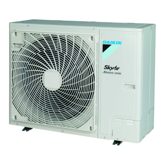
- Page 1 Installer reference guide Sky Air Advance-series Installer reference guide RZA200D7Y1B English Sky Air Advance-series RZA250D7Y1B...
-
Page 2: Table Of Contents
Table of contents 6.5.3 Checking refrigerant piping: Setup....... 19 Table of contents 6.5.4 To check for leaks............19 6.5.5 To perform vacuum drying ........... 19 To insulate the refrigerant piping..........19 Charging refrigerant ..............19 1 General safety precautions 6.7.1 About charging refrigerant ........... -
Page 3: Meaning Of Warnings And Symbols
(on top of the and cause malfunction of the equipment. instructions described in the Daikin documentation). ▪ In places where there is a risk of fire due to the leakage of flammable gases (example: thinner or gasoline), carbon fibre, CAUTION ignitable dust. - Page 4 ▪ Joints made in installation between parts of refrigerant system shall be accessible for maintenance purposes. WARNING Make sure installation, servicing, maintenance and repair comply with instructions from Daikin and with applicable legislation (for example national gas regulation) and are executed only by authorised persons. Installation space requirements NOTICE ▪...
-
Page 5: Refrigerant
1 General safety precautions Ceiling-mounted Wall-mounted Floor-standing DANGER: RISK OF EXPLOSION unit unit unit Pump down – Refrigerant leakage. If you want to pump m (kg) m (kg) m (kg) down the system, and there is a leak in the refrigerant ≤1.842 —... -
Page 6: Brine
1 General safety precautions CAUTION WARNING When the refrigerant charging procedure is done or when ▪ ONLY use copper wires. pausing, close valve refrigerant tank ▪ Make sure the field wiring complies with the applicable immediately. If the valve is NOT closed immediately, legislation. -
Page 7: About The Documentation
Technical engineering data ▪ A subset of the latest technical data is available on the regional Daikin website (publicly accessible). ▪ The full set of latest technical data is available on the Daikin Business Portal (authentication required). Installer reference guide at a... -
Page 8: To Handle The Outdoor Unit
4 About the units and options Prerequisite: Open the service cover. See "6.2.2 To open the 3.2.2 To handle the outdoor unit unit" [ 4 13]. outdoor CAUTION (10 N·m) To avoid injury, do NOT touch the air inlet or aluminium fins of the unit. -
Page 9: Combining Units And Options
5 Preparation Code Explanation WARNING European market The appliance shall be stored in a room without continuously operating ignition sources (example: open Minor model change indication flames, an operating gas appliance or an operating electric heater). Combining units and options 5.2.1 Installation site requirements of the 4.3.1... -
Page 10: Additional Installation Site Requirements Of The Outdoor Unit In Cold Climates
5 Preparation ▪ Sound sensitive areas (e.g. near a bedroom), so that the It is recommended to install the outdoor unit with the air inlet facing operation noise will cause no trouble. the wall and NOT directly exposed to the wind. Note: If the sound is measured under actual installation conditions, the measured value might be higher than the sound pressure level mentioned in Sound spectrum in the data book due... - Page 11 5 Preparation Refrigerant branch kit Branch pipes ▪ Install the branch pipes horizontally (with a maximum inclination of 15°) or vertically. Refrigerant piping material ▪ Make the length of the branch pipes to the ▪ Piping material: Phosphoric acid deoxidised seamless copper. indoor units as short as possible.
-
Page 12: Refrigerant Piping Insulation
5 Preparation Requirement Limit 4 Maximum difference between branch piping Twin: L2–L3≤limit 10 m length Triple: L2–L4≤limit 10 m Double twin: 10 m ▪ L2–L3≤limit ▪ L4–L5≤limit ▪ L6–L7≤limit ▪ (L2+L4)–(L3+L7)≤limit 5 Maximum height between indoor and outdoor Pair, twin, triple and double twin: H1≤limit 30 m 6 Maximum height between indoors Twin, triple and double twin: H2≤limit... -
Page 13: Installation
6 Installation Installation Mounting the outdoor unit 6.3.1 About mounting the outdoor unit Overview: Installation Typical workflow This chapter describes what you have to do and know on-site to Mounting the outdoor unit typically consists of the following stages: install the system. Providing the installation structure. -
Page 14: To Install The Outdoor Unit
6 Installation NOTICE NOTICE Fix the outdoor unit to the foundation bolts using nuts with If drain holes of the outdoor unit are covered by a mounting resin washers (a). If the coating on the fastening area is base or by floor surface, raise the unit to provide a free stripped off, the metal can rust easily. -
Page 15: Connecting The Refrigerant Piping
6 Installation 6.4.3 Pipe bending guidelines Connecting the refrigerant piping Use a pipe bender for bending. All pipe bends should be as gentle 6.4.1 About connecting the refrigerant piping as possible (bending radius should be 30~40 mm or larger). Before connecting the refrigerant piping 6.4.4 To connect the refrigerant branching kit Make sure the outdoor and indoor unit are mounted. -
Page 16: To Remove The Pinched Pipes
6 Installation Tightening torques Stop valve Tightening torque (N•m) (when opening or size (mm) closing) Valve body Hexagonal Service port wrench Ø9.5 4 mm 10.7~14.7 Service port and service port cover Ø12.7 8~10 Stop valve Field piping connection Ø15.9 14~16 6 mm Dust cap Ø19.1 19~21... -
Page 17: To Connect The Refrigerant Piping To The Outdoor Unit
6 Installation WARNING NOTICE Precautions when making knockout holes: ▪ Avoid damaging the casing and underlying piping. ▪ After making the knockout holes, we recommend to remove the burrs and paint the edges and areas around the edges using repair paint to prevent rusting. Never remove the pinched piping by brazing. -
Page 18: Checking The Refrigerant Piping
6 Installation Checking the refrigerant piping 6.5.1 About checking the refrigerant piping The outdoor unit's internal refrigerant piping has been factory tested for leaks. You only have to check the outdoor unit's external refrigerant piping. Before checking the refrigerant piping Make sure the refrigerant piping is connected between the outdoor unit and the indoor unit. -
Page 19: Checking Refrigerant Piping: Setup
6 Installation 6.5.3 Checking refrigerant piping: Setup If the pressure… Then… Increases There is moisture in the system. Go to the next step. 3 Vacuum the system for at least 2 hours to a manifold pressure of −0.1 MPa (−1 bar). 4 After turning the pump OFF, check the pressure for at least 1 hour. -
Page 20: About The Refrigerant
6 Installation What When Completely recharging refrigerant Example: ▪ When relocating the system. ▪ After a leak. Charging additional refrigerant Before charging additional refrigerant, make sure the outdoor unit's external refrigerant piping is checked (leak test, vacuum drying). INFORMATION Depending on the units and/or the installation conditions, it might be necessary to connect electrical wiring before you can charge refrigerant. -
Page 21: Precautions When Charging Refrigerant
6 Installation WARNING Then (L1+L2+L3+L4+L5+L6+L7)> You must add additional The refrigerant inside the unit is mildly flammable, but chargeless length refrigerant. normally does NOT leak. If the refrigerant leaks in the room and comes in contact with fire from a burner, a For future servicing, encircle the heater, or a cooker, this may result in fire, or the formation selected amount in the tables... -
Page 22: Completely Recharging Refrigerant
6 Installation Examples Activating the vacuum mode is done by operating the push buttons BS* on the PCB (A1P) and reading the feedback from the 7‑segment Layout Additional refrigerant amount (R) displays. L2=7 m Case: Twin, standard liquid pipe size (Ø9.5 mm) Operate the switches and push buttons with an insulated stick (such 1 G1 Total Ø9.5 =>... -
Page 23: To Fix The Fluorinated Greenhouse Gases Label
6 Installation 1 If not already done (for vacuum drying of the unit), activate the ▪ EN/IEC 61000‑3‑12 provided that the short-circuit power S vacuum mode (see "To activate/deactivate the vacuum mode greater than or equal to the minimum S value at the interface setting" [ 4 22]) field... -
Page 24: Specifications Of Standard Wiring Components
6 Installation 2 Strip insulation (20 mm) from the wires. Wire type Installation method Single-core wire AA´ A´ Strip wire end to this point Excessive strip length may cause electrical shock or leakage. 3 Connect the interconnection cables and power supply as a Curled single-core wire follows: b Screw... -
Page 25: Finishing The Outdoor Unit Installation
6 Installation Cable tie Knockout hole Burr 4 Fix the cables (power supply and interconnection cable) with a Sealant etc. cable tie to the stop valve attachment plate and route the wiring 7 Reattach the service cover. See "6.9.2 To close the outdoor according to the illustration above. -
Page 26: Commissioning
The indoor units are properly mounted. commissioning checklist is also available on the Daikin Business Portal (authentication required). In case a wireless user interface is used: The indoor unit The general commissioning checklist is complementary to decoration panel with infrared receiver is installed. -
Page 27: Error Codes When Performing A Test Run
8 Hand-over to the user 1 Perform introductory steps. 5 Stop the test run. Action Action Result Open the liquid stop valve and gas stop valve by Press at least 4 seconds. The Service Settings menu removing the cap and turning counterclockwise with a is displayed. -
Page 28: Maintenance And Service
9 Maintenance and service 3 To prevent damaging the PCB, touch a non-coated metal part Maintenance and service to eliminate static electricity before pulling out or plugging in connectors. NOTICE 4 Pull out junction connector X1A (A4P) for the fan motor in the Maintenance MUST be done by an authorized installer or outdoor unit before starting service operation on the inverter service agent. -
Page 29: Precautions When Troubleshooting
11 Disposal 10.2 Precautions when troubleshooting 11.3 To pump down WARNING DANGER: RISK OF EXPLOSION ▪ When carrying out an inspection on the switch box of Pump down – Refrigerant leakage. If you want to pump the unit, ALWAYS make sure that the unit is down the system, and there is a leak in the refrigerant disconnected from the mains. -
Page 30: 12 Technical Data
12 Technical data Technical data A subset of the latest technical data is available on the regional Daikin website (publicly accessible). The full set of latest technical data is available on the Daikin Business Portal (authentication required). 12.1 Overview: Technical data This chapter contains information about: •... -
Page 31: Piping Diagram: Outdoor Unit
12 Technical data Maximum two units can be installed. Not allowed Multiple rows of units ( b (mm) ≥100 ≤½H b≥250 ≥100 ½H <H ≤H b≥300 ≥100 ≥100 >H ≥100 ≥2000 ≥3000 ≥200 ≥100 ≥1000 ≥100 ≥1500 For better serviceability, use a distance ≥250 mm Stacked units (max. -
Page 32: Wiring Diagram: Outdoor Unit
12 Technical data (4) Legend Accumulator English Translation Legend Legend Field piping (liquid: Ø9.5 mm pinched pipe) Optional Optional Field piping (gas: Ø25.4 mm pinched pipe) Part n° Part n° Heating Description Description Cooling Printed circuit board (main) Printed circuit board (noise filter) 12.4 Wiring diagram: Outdoor unit Printed circuit board (inverter) -
Page 33: Information Requirements For Eco Design
Noise filter the accompanying documentation. Field supply 12.5 Information requirements for Eco Equipment NOT made by Daikin that can be combined with product according instructions Design accompanying documentation. Follow the steps below to consult the Energy Label – Lot 21 data of the unit and outdoor/indoor combinations. - Page 36 4P573383-1 2019.04...