Table of Contents
Advertisement
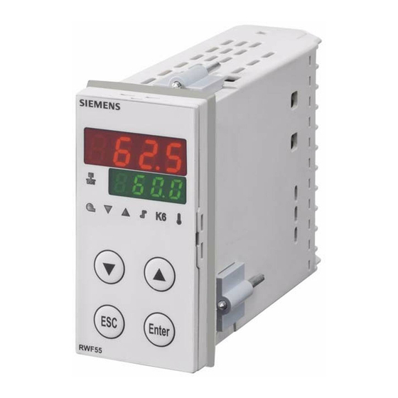
RWF55.5 and RWF55.6
Compact universal controllers
Optimized for temperature and pressure control in connection with
modulating or multistage burners and air conditioning systems
User Manual
The RWF55.5/RWF55.6 and this User Manual are intended for use by OEMs which integrate the controllers in their
products!
CC1U7867en
05.11.2013
Caution!
All safety, warning and technical notes contained in the Data Sheet on the
RWF55 (N7867) also apply to this document!
Building Technologies Division
Infrastructure & Cities Sector
Advertisement
Table of Contents

Related Manuals for Siemens RWF55.5


Summary of Contents for Siemens RWF55.5
- Page 1 Optimized for temperature and pressure control in connection with modulating or multistage burners and air conditioning systems User Manual The RWF55.5/RWF55.6 and this User Manual are intended for use by OEMs which integrate the controllers in their products! Caution! All safety, warning and technical notes contained in the Data Sheet on the...
- Page 2 2/93 Building Technologies Division User Manual RWF55... CC1U7867en Infrastructure & Cities Sector 05.11.2013...
- Page 3 Supplementary documentation Data Sheet RWF55 ....................N7867 Environmental Declaration RWF55 ................. E7867 3/93 Building Technologies Division User Manual RWF55... CC1U7867en Infrastructure & Cities Sector Introduction 05.11.2013...
- Page 4 4/93 Building Technologies Division User Manual RWF55... CC1U7867en Infrastructure & Cities Sector 05.11.2013...
-
Page 5: Table Of Contents
Contents Introduction ...................... 8 General notes ....................8 Typographical conventions ................9 1.2.1 Safety notes ..................... 9 1.2.2 Warning symbols ..................... 9 1.2.3 Notification symbols ..................10 1.2.4 Presentation .................... - Page 6 Response threshold (q) .................. 34 Cold start of plant ................... 35 Thermal shock protection (TSS) ..............37 Operation ....................... 38 Meaning of display and buttons ..............38 Basic display ....................40 ...
- Page 7 10.11.1 Use of USB port : Use of ................67 10.11.2 Powering the controller via the USB port : Powering the controller via the port ........................ 67 Modbus interface ................... 68 11.1 User level ....................... 68 ...
-
Page 8: Introduction
Introduction 1.1 General notes Please read this User Manual before switching on the controller. Keep the User Manual in a safe place which can be accessed by all users at all times. Version! This User Manual describes all necessary settings (applicable to controller software version XXX.01.01). -
Page 9: Typographical Conventions
The controller may only be used on the applications described in the technical documentation and only in connection with devices or components from other suppliers that have been approved or recommended by Siemens. The product can only function correctly and safely if shipped, stored, set up and installed correctly, and operated and maintained as specified. -
Page 10: Notification Symbols
1.2.3 Notification symbols This symbol is used to draw your special attention to a Note remark. This symbol refers to additional information in other Reference documents, chapters or sections. abc¹ Footnotes are comments, referring to specific parts of Footnote the text. -
Page 11: Description
1.3 Description The RWF55 is used primarily for the control of temperature or pressure in oil- or gas- Use in heating plants fired heating plants. Depending on the setting, it is employed as a compact 3-position controller or as a modulating controller with an analog output. An external switch is provided to convert it to a 2-position controller for controlling 2-stage burners. -
Page 12: Block Structure
1.4 Block structure Figure 1: Block structure 12/93 Building Technologies Division User Manual RWF55... CC1U7867en Infrastructure & Cities Sector 1 Introduction 05.11.2013... -
Page 13: Identification Of Product No
Identification of product no. 2.1 Type field The type field is glued onto the housing. The arrow below indicates the product no. Location Example Attention! Mains supply must correspond to the operating voltage given on the type field. Product no. Description Product nos. -
Page 14: Installation
Installation 3.1 Installation site and climatic conditions - The installation site should be free from vibrations, dust and corrosive media - The controller should be installed away from sources of electromagnetic fields, such as variable speed drives or high-voltage ignition transformers Relative humidity: 95% (noncondensing) Ambient temperature: -20...50 °C Storage temperature: -40...70 °C... -
Page 15: Side-By-Side Mounting
3.3 Side-by-side mounting If several controllers are mounted side-by-side or above one another in a control panel, the horizontal distance between panel cutouts must be a minimum of 11 mm and the vertical distance a minimum of 50 mm. 3.4 Mounting the controller in a panel cutout Remove the mounting clips Fit the seal supplied with the controller ... -
Page 16: Removing The Controller From The Panel Cutout
3.5 Removing the controller from the panel cutout Attention! When removing the controller, make certain that all cables are disconnected and that they do not get squeezed between control panel and housing. 3.6 Cleaning the front The front of the controller can be cleaned with normal washing/rinsing agents or detergents. -
Page 17: Electrical Connections
Electrical connections 4.1 Installation notes - The choice of cable, installation and electrical connections of the controller must Safety regulations conform to VDE 0100 Regulations for the installation of power circuits with nominal voltages below AC 1000 V, or the relevant local regulations - The electrical connections must be made by qualified personnel - If contact with live parts is possible while working on the unit, the controller must be disconnected from power supply (all-polar disconnection) -
Page 18: Galvanic Separation
4.2 Galvanic separation The illustration shows the maximum test voltages between the electrical circuits. InP1 Analog input Air damper control InP2 3-position output K2, K3, KQ Analog input InP3 Analog input - Relay K2 (NO contact): For resistance thermometer, Controlling element open thermo elements or standard signals - Relay K3 (NO contact):... -
Page 19: Assignment Of Terminals
4.3 Assignment of terminals Caution! Electrical connections must always be made by qualified personnel! 7867z01/0712 Figure 5: Assignment of terminals Outputs Display LED Terminal no. Connection diagram pole Relay Burner release: Relay K1: 1P, 1N NO contact 7866a01/0911 NO contact 3-position output: common pole Relay K3: Controlling element... - Page 20 InP1 (actual value) Analog input Terminal no. Connection diagram Thermal element 7867a13/0612 Resistance thermometer in 3-wire circuit Resistance thermometer in 2-wire circuit 0...135 Ω 12 + Current input DC 0...20 mA, 4...20 mA 14 - 7867a06/0612 13 + Voltage input DC 0...5 V, DC 1...5 V, DC 0...10 V 14 - 7867a07/0612...
- Page 21 Binary inputs binF Terminal no. Connection diagram Binary input D1 Binary input D2 Common ground DG 7867a18/0612 Power supply Terminal no. Connection diagram L1 Live conductor Power supply AC 110...240 V +10%/-15%, 48...63 Hz Neutral conductor 7866a09/0911 DC 24 V 10% Power supply measuring transducer max.
-
Page 22: Operating Modes
Operating modes 5.1 Low-fire operation Low-fire operation means that only small amounts of heat are drawn from the boiler. Using relay K1 Burner release, the 2-position controller ensures control to the setpoint by switching the burner on and off like a thermostat. This mode of control is known as the thermostat function. -
Page 23: High-Fire Operation
5.2 High-fire operation High-fire operation means that large amounts of heat are drawn from the boiler so that the burner runs continuously. If the heating load during low-fire operation rises to a level where the actual value begins to fall below switch-on threshold HYS1 , the controller will not immediately switch to a higher burner output, but first makes a dynamic test of the control deviation and switches to the higher output only when an adjustable threshold (q) is exceeded (A). -
Page 24: Modulating Burner, Analog Output
5.2.2 Modulating burner, analog output Thermostat function active. Area (1) The RWF55 as a modulating controller provides control to the adjusted setpoint. Area (2) Angular positioning is ensured via the analog output in the form of a standard signal. 7866d06/0911 Figure 9: Control sequence of modulating burner, analog output The controller behaves as described in chapter 5.2.1 Modulating burner, 3-position Area (3) -
Page 25: 2-Stage Burner, 3-Position Output
5.2.3 2-stage burner, 3-position output In area (1), the thermostat function is active. In area (2), the RWF55 as a 2-position controller acts on the second stage via relay K2 (OPEN) and relay K3 (CLOSE) by switching on at switch-on threshold HYS1 and switching off at switch-off threshold HYS2. 7866d07/0911 Figure 10: Control sequence of 2-stage burner, 3-position output In area (3), the actual value exceeds the upper switch-off threshold HYS3 and the... -
Page 26: 2-Stage Burner, Analog Output
5.2.4 2-stage burner, analog output In this case, a digital standard signal switches the second stage on via the analog output (terminals A+ and A-) when reaching switch-on threshold HYS1 and off at the lower switch-off threshold HYS2. 7866d08/0911 Figure 11: Control sequence of 2-stage burner, analog output If the controller is set to cooling mode, the respective values of HYS4, HYS5 and HYS6 Cooling controller apply. -
Page 27: Burner Shutdown
5.3 Burner shutdown In the event of a sensor failure, the controller cannot monitor the actual value of the boiler temperature (analog input InP1). Burner shutdown will automatically be triggered to guard against overheating. The same applies to acquiring the external setpoint using analog input InP2. - Burner off Functions - 3-position output for closing the controlling element... -
Page 28: Predefined Setpoint
5.4 Predefined setpoint The setpoints (SP1, SP2 or dSP) are predefined within the selected setpoint limits via the buttons or the ACS411 software. It is possible to shift the setpoint using either an analog or a binary signal, to change it via an external contact, or to influence it using a weather-compensated method. -
Page 29: Setpoint Changeover Sp1 / Sp2 Or Setpoint Shift Analog Via Inp2
5.4.1 Setpoint changeover SP1 / SP2 or setpoint shift analog via InP2 See chapter 8.3 Analog input InP3 InP3 (outside temperature) See chapter 5.5 Weather compensated Heating curve setpoint shifting Factory setting: = -10, See chapter 7 Parameterization PArA = 60, = 20, = 50 InP3... -
Page 30: Setpoint Changeover Sp1 / External Setpoint Via Inp2
5.4.2 Setpoint changeover SP1 / external setpoint via InP2 See chapter 8.3 Analog input InP3 InP3 (outside temperature) See chapter 5.5. Weather-compensated Heating curve setpoint shifting Factory setting: = -10, See chapter 7 Parameterization PArA = 60, = 20, = 50 InP3 Function InP3... -
Page 31: Setpoint Shifting Sp1 Analog Via Inp2 / Binary Via Dsp
5.4.3 Setpoint shifting SP1 analog via InP2 / binary via dSP See chapter 8.3 Analog input InP3 InP3 (outside temperature) See chapter 5.5 Weather-compensated Heating curve setpoint shifting Factory setting: = -10, See chapter 7 Parameterization PArA = 60, = 20, = 50 InP3 Function... -
Page 32: External Setpoint, Setpoint Shifting Binary Via Dsp
5.4.4 External setpoint, setpoint shifting binary via dSP See chapter InP2 FnC2 Function 8.2 Analog input InP2 Function of binary input D1: binI = 2 binI = 1 binI = 0, 3 Setpoint changeover: SPH oLHi SPL oLLo Binary input circuit D1: See chapter 4.3 Assignment of terminals Active setpoint Figure 15: External setpoint, setpoint shifting binary via dSP... -
Page 33: Weather-Compensated Setpoint Shifting
5.5 Weather-compensated setpoint shifting The RWF55 can be configured so that weather-compensated setpoint shifting is activated when an LG-Ni1000 outside sensor or a Pt1000 is connected. Reference! See chapter 8.3 Analog input InP3 To take into account the time response of a building, weather-compensated setpoint shifting uses the attenuated outside temperature rather than the current outside temperature. -
Page 34: Response Threshold (Q)
5.6 Response threshold (q) The response threshold (q) defines for what period of time and how much the actual value is allowed to drop before the system switches to high-fire operation. An internal mathematical calculation using an integration function determines the sum of all areas qeff = q1 + q2 + q3 as shown in the graph. -
Page 35: Cold Start Of Plant
5.7 Cold start of plant Note! Interlocking Functions Cold start of plant and Thermal shock protection (TSS) are interlocked. Only one function can be activated, but never both at the same time. When a heating system is switched off for a longer period of time, the actual value will Heating controller drop of course. - Page 36 Cold start of plant also works when the RWF55 is used as a cooling controller. Cooling controller In that case, the limit value is calculated as follows: Limit value = 2 x (HYS4-HYS6) Operating mode: Modulating 3-position output Example HYS4 = 5 K HYS6 = -5 K w = -30 °C Limit value = 2 x (5 + 5) = 2 x (10) = +20 K...
-
Page 37: Thermal Shock Protection (Tss)
5.8 Thermal shock protection (TSS) Note! Interlocking Functions Cold start of plant and Thermal shock protection (TSS) are interlocked. Only one function can be activated, but never both at the same time. The controller comes with thermal shock protection (TSS) deactivated; it can be activated at the configuration level. -
Page 38: Operation
Operation 6.1 Meaning of display and buttons Burner release Controlling element CLOSED/stage 1 Controlling element OPEN/stage 2 Operating mode 2-stage Actual value display (red) and parameter value USB-LED Communication via interface Setpoint display (green) and parameter symbol Thermal shock protection Alarm function Decrease value Increase value... - Page 39 The actual value display (red) shows 9999 flashing Alarm message. Flashing actual value display Reference! See chapter 13 What to do if ... The setpoint display (green) shows HAnd flashing. Manual control Reference! See chapter 6.4 Manual control of a modulating burner. 39/93 Building Technologies Division User Manual RWF55...
-
Page 40: Basic Display
6.2 Basic display When switching power on, the displays show hyphens for about 5 seconds. Figure 21: Display start The state that follows is called normal display. Default display is the actual value and the current setpoint. Other values can be displayed via configuration level or via PC software ACS411. ... -
Page 41: User Level
6.3 User level This level is started from the basic display. Setpoints SP1, SP2 or dSP can be altered. The values of the analog inputs InP1, InP2, InP3 and SPE (external setpoint) and InP3 (actual angular positioning between 0...100%) can be displayed. Changing SP1, SP2 or dSP. -
Page 42: Manual Control, Modulating Burner
6.4 Manual control, modulating burner Note! Manual control can only be activated if the thermostat function energized relay K1. If the thermostat function deenergized relay K1 during manual control, manual control is ended. Press for 5 seconds HAnd appears on the lower display, alternating with the value for manual control (with continuous controller). -
Page 43: Manual Control, 2-Stage Burner
6.5 Manual control, 2-stage burner Note! Manual control can only be activated if the thermostat function active relay K1. If the thermostat function inactive relay K1 during manual control, manual control is ended. Press for 5 seconds Press briefly Relay K2 / K3 Analog output A- / A+ Relay K2 is active... -
Page 44: Starting The Self-Setting Function
6.6 Starting the self-setting function Start Press for 5 seconds Cancel Cancel with 7867z04/0612 Figure 23: Display of self-setting function When tUnE stops flashing, the self-setting function has been ended. The parameters calculated by the controller are automatically adopted! Note! It is not possible to start tUnE in manual control or low-fire operation. -
Page 45: Display Of Software Version
6.7 Display of software version Press 7867z05/0612 Figure 24: Display of software version Segment test Press again. 7867z25/0612 Figure 25: Display segment test All display segments and LEDs light up; the actual value display (red) flashes for about 10 seconds. 45/93 Building Technologies Division User Manual RWF55... -
Page 46: Parameterization Para
Parameterization PArA Here, set the parameters associated directly with the controller’s adaptation to the controlled system after the plant has been put into operation. Note! The display of the individual parameters depends on the type of controller. Basic display Enter Enter User level OPr... - Page 47 Display of controller The parameters are shown on the lower setpoint display (green) and their values on the parameters upper/actual value display (red). Factory Parameter Display Value range Remarks setting Proportional band ¹ 1...9999 digit Influences the controller’s P-action Influences the controller’s D-action Derivative time 0...9999 s With dt = 0, the controller has no D-action...
- Page 48 Factory Parameter Display Value range Remarks setting Outside temperature -40...120 Reference! Curve point 1 ¹ See chapter 5.5 Weather-compensated setpoint shifting SPL...SPH Boiler temperature Reference! Curve point 1 ¹ See chapter 5.5 Weather-compensated setpoint shifting Outside temperature -40...120 Reference! Curve point 2 ¹...
-
Page 49: Configuration Conf
Configuration ConF Here, the settings (e.g. acquisition of measured value or type of controller) required directly for commissioning a certain plant are made and, for this reason, there is no need to change them frequently. Basic display Enter Enter User level OPr Enter Parameter level PArA Pb1 dt rt db tt... -
Page 50: Analog Input Inp1
InP1 8.1 Analog input This input is used to acquire the actual value. ConF InP InP1 Parameter Value/ Description selection Sensor type Resistance thermometer Pt100, 3-wire Resistance thermometer Pt100, 2-wire SEn1 Sensor type Resistance thermometer Pt1000, 3-wire Resistance thermometer Pt1000, 2-wire Resistance thermometer LG-Ni1000, 3-wire Resistance thermometer LG-Ni1000, 2-wire... - Page 51 Parameter Value/ Description selection 0.0... Is used to adapt the digital 2nd order input filter (time in s; 0 s = filter off) Filter time constant 0.6... Digital filter 100.0... If the input signal changes abruptly, about 26% of the change are captured after a time corresponding to the filter time constant dF (2 x dF: approx.
-
Page 52: Analog Input Inp2
8.2 Analog input InP2 This input can be used to specify an external setpoint or carry out setpoint shifting. ConF InP InP2 Parameter Value/ Description selection Function No function External setpoint (display SPE) FnC2 Setpoint shifting (display dSP) Angular positioning feedback Sensor type 0...20 mA... -
Page 53: Analog Input Inp3
8.3 Analog input InP3 This input is used to acquire the outside temperature. ConF InP InP3 Parameter Value/ Description selection Sensor type Switched-off Resistance thermometer Pt1000 in 2-wire circuit SEn3 Sensor type Resistance thermometer LG-Ni1000 in 2-wire circuit Function No function Weather-compensated setpoint... -
Page 54: Controller Cntr
8.4 Controller Cntr Here, the type of controller, operating action, setpoint limits and presettings for self- optimization are selected. ConF Cntr Parameter Value/ Description selection Controller type 3-position controller Modulating controller CtYP Controller type Cooling controller Operating action CACt Heating controller Control direction... -
Page 55: Thermal Shock Protection (Tss) Rafc
8.5 Thermal shock protection (TSS) rAFC The RWF55… can be operated as a fixed value controller with or without ramp function. ConF rAFC Parameter Value/ Description selection Function Switched off Gradient Kelvin/minute FnCt Function Gradient Kelvin/hour Note! With FnCt = 1 or 2, Thermal shock protection (TSS) is automatically activated as soon as the actual value drops below the adjustable absolute limit value rAL (heating controller) or... -
Page 56: Alarm Function Af
8.6 Alarm function AF ConF AF The alarm function can be used to monitor the analog inputs. If the limit value is exceeded, multifunctional relay K6 is activated (depending on the switching characteristic). The alarm function can have different switching functions (lk1 to lk8) and can be set to a deviation from the active setpoint or to a fixed limit value. - Page 57 Parameter Value/ Description selection Function Without function lk1 monitored input InP1 FnCt Function lk2 monitored input InP1 lk3 monitored input InP1 lk4 monitored input InP1 lk5 monitored input InP1 lk6 monitored input InP1 lk7 monitored input InP1 lk8 monitored input InP1 lk7 monitored input InP2 lk8 monitored input InP2 lk7 monitored input InP3...
-
Page 58: Control Outputs Outp
8.7 Control outputs OutP For fuel-air ratio control purposes, the RWF55 has the binary outputs (K2, K3) and the analog output (A+, A-). The burner is released via relay K1. The switching states of relay K1 Burner release (LED green), relay K2 Controlling element OPEN, and relay K3 Controlling element CLOSE (yellow LED arrows) are indicated on the controller front. -
Page 59: Binary Input Binf
8.8 Binary input binF This setting decides on the use of the binary inputs. Reference! See chapter 5.4 Preselected setpoint ConF binF Parameter Value/ Description selection Binary inputs No function Setpoint changeover bin1 Binary input 1 Setpoint shift Alarm input bin2 Changeover of operating mode... -
Page 60: Display Disp
8.9 Display diSP By configuring the position of the decimal point and automatic changeover (timer), both tout LED indications can be adapted to the respective requirements. Timeout operation and the locking of levels can be configured as well. ConF dISP Parameter Value/ Description... -
Page 61: Interface Intf
8.10 Interface IntF The controller can be integrated into a data network using an optional RS-485 interface or an optional Profibus DP interface. ConF IntF Parameter Value/ Description selection Baud rate 4800 Baud 9600 Baud bdrt Baud rate 19200 Baud 38400 Baud 0... -
Page 62: Self-Setting Function
Self-setting function 9.1 Self-setting function in high-fire operation Note! tUnE is only possible in high-fire operation, in modulating burner mode. Self-setting function tUnE is a proper software function unit integrated in the controller. In modulating mode, tUnE tests in high-fire operation the response of the controlled system to angular positioning steps according to a special procedure. - Page 63 The tUnE function uses 2 different methods that are automatically selected depending 2 procedures on the dynamic state of the actual value and the deviation from the setpoint at startup. tUnE can be started from within any dynamic actual value sequence. If there is a great difference between actual value and setpoint when tUnE is activated, a switching line is established about which the controlled variable performs forced oscillations during the self-setting process.
-
Page 64: Checking The Controller Parameters
9.2 Checking the controller parameters Optimum adjustment of the controller to the controlled system can be checked by recording a startup sequence with the control loop closed. The following diagrams indicate possible incorrect adjustments, and their correction. Example The response to a setpoint change is shown here for a 3rd order controlled system for a PID controller. -
Page 65: Pc Software Acs411
10 PC software ACS411 PC software ACS411 is an operating module for use with the RWF55… universal controller and designed for the following basic tasks: Visualization of system state covering the following data: - Parameters - Process data - Configuration and parameterization of the controller (individual parameters) - Saving and restoration of parameter sets A USB cable can be used to establish the connection between PC (USB plug type A, 4 pins) and RWF55 (USB plug type Mini B, 5 pins). -
Page 66: Place Of Installation
10.4 Place of installation Caution! PC software ACS411 is designed for use on site, that is, within viewing and hearing distance of the respective combustion plant. This means that remote control is not permitted. 10.5 License and liability regulations Note! ... -
Page 67: Installation
10.10 Installation Note! First, install PC software ACS411; then, connect the controller. If not observed, an error message is delivered. PC software ACS411 is supplied on a CD. Insert CD in the CD or DVD drive. Setup starts automatically. Follow the instructions appearing on the screen. -
Page 68: Modbus Interface
11 Modbus interface The tables that follow in this chapter specify the addresses of the readable and writable words that the customer is able to access. The customer may read and/or write the values using SCADA programs, PLCs, or similar. The entries under Access have the following meanings: Read Only, value can only be read Read/Write, value can be read and written... -
Page 69: Parameter Level
11.2 Parameter level Address Access Data type Signal reference Parameter 0x3000 Float Proportional range 1 0x3004 Float Derivative action time 0x3006 Float Integral action time 0x300C Float Dead band 0x3012 Word Controlling element running time 0x3016 Float Switch-on threshold HYS1 0x3018 Float Switch-off threshold... -
Page 70: Configuration Level
11.3 Configuration level Address Access Data type Signal reference Parameter 0x3426 Float Start of display input 1 SCL1 0x3428 Float End of display input 1 SCH1 0x3432 Float Start value input 2 SCL2 0x3434 Float End value input 2 SCH2 0x3486 Float Start of setpoint limitation... -
Page 71: Device Data
11.5 Device data Address Access Data type Signal reference Parameter 0x8000 Char12 Software version 0x8006 Char14 VdN number 11.6 Device state Address Access Data type Signal reference Parameter 0x0200 Word Outputs and states Bit 0 Output 1 Bit 1 Output 3 Bit 2 Output 2 Bit 3... -
Page 72: Profibus-Dp Interface
12 Profibus-DP interface 12.1 RS-485 Technology transfer Transmission is carried out in accordance with the RS-485 standard. This covers all areas in which high transmission speeds and simple, inexpensive installation technology are required. A twisted, shielded copper cable with a wire pair is used for this purpose. - Page 73 Bus terminator At the beginning and end of each segment, the bus is terminated by terminators. To enable fault-free operation, you must ensure that the two bus terminators are constantly supplied with power. The terminators are located in the Profibus connectors and can be activated by moving the slide switch to ON.
- Page 74 Additionally, where possible you must ensure that data lines are laid separately from all power cables. As an example of an appropriate cable, we recommend the following from Siemens: Simatic Net Profibus 6XV1 Order no.: 830-0AH10 * (UL) CMX 75 °C (Shielded) AWG 22 * Data rate With data rates of ≥1.5 Mbit/s, branching must be avoided during installation.
- Page 75 Wiring and bus VP (pin 6) termination DGND 390 Ohm RxD/TxD-N RxD/TxD-P RxD/TxD-P (pin 3) 220 Ohm RxD/TxD-N (pin 8) 7867z22e/0712 390 Ohm Protective DGND (pin 5) earth PE Connector Wiring Bus termination Figure 39: Wiring and bus termination Profibus DP is designed for fast data exchange at field level. In this case, the central control devices (such as the PLC/PC) communicate with distributed field devices (such as I/Os, screen recorders, and controllers) via a fast serial connection.
- Page 76 Protection functions Threshold monitoring for DP slaves Access protection for inputs/outputs of DP slaves Monitoring of user data traffic with adjustable monitoring timer for DP master Device types DP master class 2, e.g., programming/configuration devices DP master class 1, e.g., central automation devices such as PLC, PC, etc.
-
Page 77: Wiring
12.2 Wiring Assignment of 9-pole D- Pin: Signal on COM2 Description SUB jack the device D-SUB terminal strip 1 jack C1: VP Power supply - plus C2: RxD/TxD-P Received data/transmission data - plus C3: RxD/TxD-N Received data/transmission data - minus 7867z26/0612 Figure 41: COM2 D-SUB jack C4: DGND... -
Page 78: What To Do If
13 What to do if ... 13.1 Alarm messages Display Cause Remedy 9999 flashing Check to see if sensor and Measured value exceeded connecting line are damaged or limit The measured value is too have a short-circuit great, lies outside the ... -
Page 79: Technical Data
Technical data 14.1 Inputs 14.1.1 Analog input InP1 (actual value) For resistance thermometers, thermal elements or standard signals with 2nd order digital filters (configurable). Sampling time 250 ms Resistance Type Measuring Measuring Impact of thermometers range accuracy ambient temperature 0,05% Pt100;... - Page 80 Standard signals Measuring range Measuring Impact of ambient accuracy temperature 0.2% Voltage DC 0...5 V 200 ppm/K Input resistance R >2 M 0.1% Voltage DC 0...10 V 100 ppm/K Input resistance R >2 M 0.2% Voltage DC 1...5 V 200 ppm/K Input resistance R >2 M...
-
Page 81: Analog Input Inp2 (External Setpoint, Setpoint Shifting)
14.1.2 Analog input InP2 (external setpoint, setpoint shifting) Resistance measurement 0...1 k or standard signals without linearization. Sampling time 750 ms Resistance Resistance (2-wire circuit) 0...1 k linear 0.05% thermometer 50 ppm/K Standard signals Measuring range Measuring Impact of ambient temperature accuracy 0.2%... -
Page 82: Binary Input D2
14.1.5 Binary input D2 Potentialfree contact for operating mode changeover: Burner modulating, if contacts D2 and DG LED operating mode, 2-stage, does not are open light up on the front Burner 2-stage, if contacts D2 and DG LED operating mode, 2-stage, lights up are closed on the front 82/93... -
Page 83: Monitoring The Measuring Circuit
14.2 Monitoring the measuring circuit In the event of error, the outputs assume defined states (configurable). Measuring Measured value Sensor/line has Sensor/line transducer crossed limit short-circuit interrupted ● ● ● Resistance thermometer ● ● Thermal elements Voltage ● ● ● DC 1...5 V (●) DC 0...5 V... -
Page 84: Controller Outputs Outp Controller O
14.3 Controller outputs OutP Controller o Galvanic separation between supply voltage, analog inputs, and controller outputs. Reference! See chapter 4.2 Galvanic separation Relay K1 (NO contact) 1P, 1N (burner release) Contact rating Max. 2 A at AC 240 V at cosφ >0.6 Contact life 250,000 switching cycles at high-fire Contact protection... -
Page 85: Controller
To DIN EN 60529 Front side IP66 Rear IP20 To UL50E and to NEMA 250 Front side type 5 Weight (Fully equipped) - RWF55.5 Approx. 329 g - RWF55.6 Approx. 342 g 85/93 Building Technologies Division User Manual RWF55... CC1U7867en Infrastructure &... -
Page 86: Environmental Conditions
14.7 Environmental conditions DIN IEC 60721-3-1 Storage Climatic conditions Class 1K3 Mechanical conditions Class 1M2 Temperature range -40...70 °C Humidity <95% r.h. DIN IEC 60721-3-2 Transport Climatic conditions Class 2K2 Mechanical conditions Class 2M2 Temperature range -40...70 °C Humidity <95% r.h. DIN IEC 60721-3-3 Operation Climatic conditions... -
Page 87: Key
Switch-on point for high-fire when response threshold (q) is reached ACrA Response by Out of Range Device address Modbus Alarm function Limit value Outside temperature 1 Outside temperature 2 Switch-off point for burner bdrt Baudrate Binary input 1 bin1 Binary input 2 bin2 Binary input binF... - Page 88 Parameter PArA Proportional range Proportional range 1 Response threshold qeff Sum of all integrals Thermal shock protection rAFC Limit value Ramp slope rASL Value when out of range rOut Integral action time End of display SCH1 End of display SCH2 Start of display SCL1 Start of display...
-
Page 89: List Of Figures
16 List of figures Figure 1: Block structure ....................12 Figure 2: Dimensions of RWF55..................14 Figure 3: Mounting in a panel cutout ................15 Figure 4: Test voltages ....................18 Figure 5: Assignment of terminals ................. 19 ... - Page 90 Figure 36: rt, dt too large ..................... 64 Figure 37: Optimum adjustment ..................64 Figure 38: Bus terminator ..................... 73 Figure 39: Wiring and bus termination ................75 Figure 40: User data transfer with Profibus DP ............76 ...
- Page 91 Index Product nos............13 A Scope of delivery ..........13 ACS411 Changing the parameters ......... 65 Type field ............13 Installation ............67 Installation ............... 14 Languages ............66 Cleaning the front ..........16 License and liability regulations ...... 66 Dimensions ............
- Page 92 Modulating burner, analog output ....24 Wiring ..............77 Operating mode changeover ......23 R Predefined setpoint ........... 28 RS-485 Technology transfer Response threshold (q) ........34 Basic features ............. 72 Setpoint changeover SP1 / external setpoint via Basic functions ............ 75 InP2 ..............
- Page 93 Siemens AG Infrastructure & Cities Sector Building Technologies Division © 2013 Siemens AG Infrastructure & Cities Sector Berliner Ring 23 Building Technologies Division D-76437 Rastatt Subject to change! Tel. +49 7222 598 279 Fax +49 7222 598 269 www.siemens.com 93/93 Building Technologies Division User Manual RWF55...