Table of Contents
Advertisement
Quick Links
Form No. 3374-992 Rev A
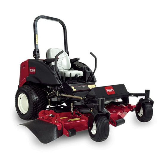
Groundsmaster
®
7200 and 7210
Mower
Model No. 30363N—Serial No. 313000001 and Up
Model No. 30464N—Serial No. 313000001 and Up
Model No. 30465N—Serial No. 313000001 and Up
Model No. 30468N—Serial No. 313000001 and Up
To register your product or download an Operator's Manual or Parts Catalog at no charge, go to www.Toro.com.
Original Instructions (EN)
Advertisement
Table of Contents

Related Manuals for Toro 30363N


Summary of Contents for Toro 30363N
- Page 1 Model No. 30464N—Serial No. 313000001 and Up Model No. 30465N—Serial No. 313000001 and Up Model No. 30468N—Serial No. 313000001 and Up To register your product or download an Operator's Manual or Parts Catalog at no charge, go to www.Toro.com. Original Instructions (EN)
-
Page 2: Introduction
If you require a spark arrestor, contact your Authorized Toro Service Dealer. Figure 1 Genuine Toro spark arresters are approved by the USDA Forestry Service. 1. Model and serial number location Important: It is a violation of California Public... -
Page 3: Table Of Contents
Safety ................4 Fuel Lines and Connections........ 42 Safe Operating Practices ........4 Bleeding the Fuel System ........42 Toro Riding Mower Safety ........5 Bleeding Air From the Injectors ......43 Slope Indicator............. 7 Electrical System Maintenance........ 44 Safety and Instructional Decals ......8 Servicing the Battery........... -
Page 4: Safety
Safety ◊ incorrect load distribution. Preparation This Machine meets or exceeds ANSI B71.4–2004 specifications in effect at the time of production • While mowing, always wear substantial footwear and long trousers. Do not operate the equipment when Improper use or maintenance by the operator or barefoot or wearing open sandals. -
Page 5: Toro Riding Mower Safety
The following list contains safety information specific to Toro products or other safety information that you must • Before leaving the operator's position: know that is not included in the CEN standard. - Page 6 • Remove or mark obstacles such as rocks, tree limbs, etc. from the mowing area. Tall grass can hide obstacles. • Watch for ditches, holes, rocks, dips, and rises that change the operating angle, as rough terrain could overturn the machine. •...
-
Page 7: Slope Indicator
Slope Indicator G011841 Figure 3 This page may be copied for personal use. 1. The maximum slope you can safely operate the machine on is 15 degrees. Use the slope chart to determine the degree of slope of hills before operating. Do not operate this machine on a slope greater than 15 degrees. Fold along the appropriate line to match the recommended slope. -
Page 8: Safety And Instructional Decals
Safety and Instructional Decals Safety decals and instructions are easily visible to the operator and are located near any area of potential danger. Replace any decal that is damaged or lost. 107-2908 1. Thrown object hazard—keep bystanders a safe distance from the machine. - Page 9 110-8254 1. Engine–Stop 3. Engine—Start 2. Engine—Run 110-8253 1. PTO–Off 4. Continuous variable setting 2. PTO—On 5. Slow 110-9796 3. Fast 1. Read the Operator's Manual for information on fuses. 110-8252 1. Read the Operator's Manual. 3. Hydraulic oil 5. Engine coolant 2.
- Page 10 110-9774 1. Forward 3. Slow 5. Reverse 7. Tow valve location; torque the tow valves to 6.78 ± 1.13 N⋅m (60 ± 10 in-lbs). 2. Fast 4. Neutral 6. Backward 8. Read the Operator's Manual for more information on the hydraulic oil.
- Page 11 106-6755 1. Engine coolant under 3. Warning—do not touch the pressure. hot surface. 2. Explosion hazard—read 4. Warning—read the the Operator's Manual. Operator's Manual. 107-2916 1. Remove the ignition key and read the 2. Thrown object hazard—do not operate 3. Cutting/dismemberment hazard of Operator's Manual before servicing or the mower with the deflector up or hand or foot, mower blade—stay away...
- Page 12 110-9781 1. Warning—read the Operator's Manual. 2. Poison and caustic liquid/chemical burn hazard—keep children a safe distance from the battery. 3. Warning—do not touch the hot surface. 4. Cutting/dismemberment hazard, fan and entanglement hazard, belt—stay away from moving parts. 5. Hydraulic oil in system under pressure, escaping hydraulic oil penetrating skin hazard, broken hydraulic lines hazard—wear protective hand protection when handling hydraulic system components.
- Page 13 107-3069 1. Warning–there is no rollover protection when the roll bar is down. 2. To avoid injury or death from a rollover accident, keep the roll bar in the raised and locked position and wear the seat belt. Lower the roll bar only when absolutely necessary; do not wear the the seat belt when the roll bar is down.
-
Page 14: Setup
Setup Loose Parts Use the chart below to verify that all parts have been shipped. Procedure Description Qty. – No parts required Adjust the ROPS. – No parts required Check the tire pressure. Check the hydraulic fluid, engine oil, – No parts required and coolant levels. -
Page 15: Checking Fluid Levels
Product Overview Checking the Tire Pressure No Parts Required Procedure The tires are over inflated for shipping. Therefore, release some of the air to reduce the pressure. The correct air pressure is 15 psi (103 kPa) in the rear tires and 25 psi (172 kPa) in the caster wheels. - Page 16 Motion Control Levers The motion control levers control the forward and rearward motions as well as the turning of the machine. Refer to Driving Forward or Backward. Parking Brake Lever Whenever the engine is shut off, engage the parking brake to prevent accidental movement of the machine. To engage the parking brake, pull the parking brake lever rearward and up (Figure 7).
-
Page 17: Specifications
Illuminates when the system charging circuit enhance and expand its capabilities. Contact your malfunctions. Authorized Service Dealer or Distributor or go to www.Toro.com for a list of all approved attachments Oil Pressure Warning Light and accessories. The oil pressure warning light glows when the oil pressure in engine drops below a safe level. -
Page 18: Operation
Operation • The blended fuel composition should meet ASTM D975 or EN590. Note: Determine the left and right sides of the • Painted surfaces may be damaged by biodiesel machine from the normal operating position. blends. • Use B5 (biodiesel content of 5%) or lesser blends CAUTION in cold weather. -
Page 19: Filling The Fuel Tank
DANGER In certain conditions during fueling, static electricity can be released causing a spark which can ignite the fuel vapors. A fire or explosion from fuel can burn you and others and can damage property. • Always place fuel containers on the ground away from your vehicle before filling. -
Page 20: Think Safety First
WARNING There is no rollover protection when the roll bar is in the down position. • Lower the roll bar only when absolutely necessary. • Do not wear the seat belt when the roll bar is in the down position. •... -
Page 21: Operating The Parking Brake
Operating the Parking Brake DANGER Operating on wet grass or steep slopes can cause Always set the parking brake when you stop the sliding and loss of control. machine or leave it unattended. Wheels dropping over edges can cause rollovers, Setting the Parking Brake which may result in serious injury, death or drowning. -
Page 22: Starting And Stopping The Engine
The glow plug light will turn on for 6 seconds. Figure 17 1. Ignition switch 3. Run/glow pug 2. Off 4. Start Figure 15 7. After the glow plug indicator light goes out, turn the key to the Start position. When the engines starts release the key. -
Page 23: Driving The Machine
Note: The farther you move the traction control 3. Turn the ignition key to the Off position (Figure 17). Wait for all moving parts to stop before leaving the levers in either direction, the faster the machine will operating position. move in that direction. -
Page 24: Operating The Mower
Operating the Mower Raising and Lowering the Mower with the Deck Lift Lever The deck lift lever raises and lowers the mower deck (Figure 19). The engine must be running for you to use this lever. Figure 20 1. Foot operated deck lift pedal •... -
Page 25: Adjusting The Height-Of-Cut
Figure 21 1. PTO switch Disengaging the PTO To disengage, push the PTO switch to the off position. Adjusting the Height-of-Cut The height-of-cut is adjusted from 1 to 6 inches (2.5 to 15.8 cm) in 1/4 inch (6 mm) increments by relocating the stop pin into different hole locations. -
Page 26: Adjusting The Rear Anti-Scalp Rollers
Figure 23 1. Screw 3. Skid 2. Flange-head bolt 4. Nut Figure 24 1. Flange nut 4. Spacer 4. Remove the flange-head bolts and nuts from each 2. Bushing 5. Bolt skid. 3. Anti-scalp roller 5. Move each skid to the desired position and secure them with the flange-head bolts and nuts. - Page 27 2. Move the throttle lever to the Slow position, stop the engine, remove the key, and wait for all moving parts to stop before leaving the operating position. 3. Raise the front of the machine and support it on jack stands. 4.
-
Page 28: The Safety Interlock System
Testing the Safety Interlock System Service Interval: Before each use or daily Test the safety interlock system before you use the machine each time. If the safety system does not operate as described below, have an Authorized Service Dealer repair the safety system immediately. 1. -
Page 29: Positioning The Seat
Figure 32 for a description of what each light means. For details on using the rest of the SCM functions, refer to the Service Manual, available through your Authorized Toro Distributor. Figure 33 1. Back rest knob 3. Lumbar support adjustment knob 2. -
Page 30: Unlatching The Seat
Figure 34 1. Seat suspension knob 2. Operator weight setting Changing the Back Position The back of the seat can be adjusted to provide a comfortable ride. Position the back of the seat where it Figure 35 is most comfortable. 1. -
Page 31: Loading Machines
slope. This will minimize the ramp angle. The trailer or truck should be as level as possible. Important: Do not attempt to turn the unit while on the ramp; you may lose control and drive off the side. Avoid sudden acceleration when driving up a ramp and sudden deceleration when backing down a ramp. -
Page 32: Transporting Machines
Transporting Machines Operating Tips Fast Throttle Setting/Ground Speed WARNING Driving on the street or roadway without turn To maintain enough power for the machine and deck signals, lights, reflective markings, or a slow while mowing, operate the engine at the fast throttle moving vehicle emblem is dangerous and can lead position and adjust your ground speed for conditions. - Page 33 Check the blades daily for sharpness, and for any wear or damage. Sharpen the blades as necessary. If a blade is damaged or worn, replace it immediately with a genuine Toro replacement blade. Refer to Servicing the Cutting Blades.
-
Page 34: Maintenance
• Drain and clean the fuel tank. Every 2 years • Flush and replace cooling system fluid. Important: Refer to your Engine Operator's Manual for additional maintenance procedures. A detailed Service Manual is also available for purchase from your Authorized Toro Distributor. -
Page 35: Daily Maintenance Checklist
Daily Maintenance Checklist Duplicate this page for routine use. Maintenance Check Item For the week of: Mon. Tues. Wed. Thurs. Fri. Sat. Sun. Check Safety Interlock Operation Check Grass Deflector in Down Position (if applicable) Check Parking Brake Operation Check Fuel Level Check Hydraulic Oil Level Check Engine Oil Level Check Cooling System Fluid... -
Page 36: Premaintenance Procedures
CAUTION If you leave the key in the ignition switch, someone could accidently start the engine and seriously injure you or other bystanders. Remove the key from the ignition before you do any maintenance. Figure 39 Service Interval Chart Premaintenance Lubrication Procedures Greasing the Bearings and... - Page 37 Important: The fittings on the axles of the caster wheels are not illustrated. Ensure that you grease these fittings as well. Figure 40...
-
Page 38: Servicing The Mower Deck Gear Box Lubricant
Figure 41 Checking the Mower Deck Gear Box Note: Bearing life can be negatively affected by improper wash down procedures. Do not wash down the Lubricant unit when it is still hot and avoid directing high-pressure Service Interval: Every 150 hours or high volume spray at the bearings or seals. - Page 39 5. Lift the footrest, exposing the top of the mower 8. Replace the drain plug. deck. 9. Add enough lubricant, approximately 12 oz. (283 6. Remove the dipstick/fill plug from the top of the ml), until the level is between the marks on the gear box (Figure 42) and make sure that the lubricant dipstick.
-
Page 40: Engine Maintenance
Note: Toro Premium Engine oil is available from your This cleaning process prevents debris from migrating distributor in either 15W-40 or 10W-30 viscosity. See the into the intake when the primary filter is removed. - Page 41 1. Park the machine on a level surface, lower the mower deck, move the throttle lever to the Slow position, stop the engine, and remove the key from the ignition switch. Open the hood. 2. Remove the dipstick (Figure 44), wipe it clean, and install the dipstick.
-
Page 42: Fuel System Maintenance
Fuel System 5. Lubricate the gasket on the filter canister with clean oil. Maintenance 6. Install the filter canister by hand until the gasket contacts mounting surface, then rotate it an Note: Refer to Adding Fuel for proper fuel additional 1/2 turn. recommendations. -
Page 43: Bleeding Air From The Injectors
The electric fuel pump will begin operation, thereby CAUTION forcing air out around the air bleed screw. The engine may start during this procedure. Moving fans and belts in a running engine can CAUTION severely injure you or bystanders. The engine may start during this procedure. Keep hands, fingers, loose clothing/jewelry, and Moving fans and belts in a running engine can hair away from the engine fan and belt during... -
Page 44: Electrical System Maintenance
Electrical System WARNING Maintenance Incorrect battery cable routing could damage the machine and cables causing sparks. Sparks can cause the battery gasses to explode, resulting in Important: Whenever working with the electrical personal injury. system, always disconnect the battery cables, negative (-) cable first, to prevent possible wiring •... -
Page 45: Drive System Maintenance
Replacing the Castor Wheels Figure 50 and Bearings 1. Obtain a new caster wheel assembly, cone bearings, and bearing seals for your Authorized Toro Distributor. 2. Remove the locknut from the bolt holding the castor wheel assembly between the castor fork (Figure 52). -
Page 46: Cooling System Maintenance
Cooling System Maintenance DANGER Discharge of hot pressurized coolant or touching hot radiator and surrounding parts can cause severe burns. • Do not remove the radiator cap when the engine is hot. Always allow the engine to cool at least 15 minutes or until the radiator cap is cool enough to touch without burning your hand before removing the radiator cap. -
Page 47: Cleaning The Radiator
1. Check the level of the coolant in the expansion tank 3. After the radiator is thoroughly cleaned, clean out (Figure 53). The coolant level should be between the debris that may have collected in the channel at the marks on the side of the tank. radiator base. -
Page 48: Brake Maintenance
Brake Maintenance 5. Secure the switch jam nuts. 6. Test the adjustment as follows: Adjusting the Parking Brake A. Ensure that the parking brake is engaged and you are not sitting on the seat, then start the engine. Interlock Switch B. -
Page 49: Belt Maintenance
Belt Maintenance stop the engine, set the parking brake, and remove the ignition key. 2. Remove the belt covers from the top of the cutting Checking the Alternator Belt unit and set the covers aside. Service Interval: Every 200 hours 3. -
Page 50: Controls System Maintenance
Controls System 4. Holding the control lever against the frame, move the switch toward the lever until the distance between Maintenance lever and switch body is 0.015 to 0.045 inch (0.4 to 1 mm) (Figure 59). 5. Secure the switch. Adjusting the Control Lever 6. -
Page 51: Adjusting The Traction Drive For Neutral
Adjusting the Traction Drive for Neutral This adjustment must be made with drive wheels turning. DANGER Mechanical or hydraulic jacks may fail to support machine and cause a serious injury. • Use jack stands when supporting machine. • Do not use hydraulic jacks. Figure 61 1. -
Page 52: Adjusting The Maximum Ground Speed
12. Lower the seat into position. 13. Remove the jack stands. Adjusting the Maximum Ground Speed 1. Disengage the PTO, move the motion control levers to the neutral locked position and set the parking brake. 2. Move the throttle lever to the Slow position, stop the engine, remove the key, and wait for all moving parts to stop before leaving the operating position. -
Page 53: Adjusting The Tracking
5. Thread the stop bolt all the way in (away from the 4. Have someone push the control lever posts (not the control lever). control levers) all the way forward into the maximum speed position and hold them there. 6. Push the control lever all the way forward until it stops and hold it there. -
Page 54: Hydraulic System Maintenance
(Available in 5 gallon pails or 55 gallon drums. See parts catalog or Toro distributor for part numbers.) Alternate fluids: If the Toro fluid is not available, Mobil® 424 hydraulic fluid may be used. Note: Toro will not assume responsibility for damage caused by improper substitutions. -
Page 55: Mower Deck Maintenance
Check the blades daily for sharpness, and for any wear or damage. Sharpen the blades as necessary. If a blade is damaged or worn, replace it immediately with a genuine Toro replacement blade. - Page 56 DANGER A worn or damaged blade can break, and a piece of the blade could be thrown into the operator's or bystander's area, resulting in serious personal injury or death. • Inspect the blade periodically for wear or damage. • Replace a worn or damaged blade. Inspect and check the blades every 8 hours.
- Page 57 Blades must be replaced if a solid object is hit, if the blade is out of balance or is bent. To ensure optimum Installing the Blades performance and continued safety conformance of the machine, use genuine Toro replacement blades. 1. Install the blade onto the spindle shaft (Figure 75).
-
Page 58: Correcting Mower Deck Mismatch
1. Spindle 3. Anti-scalp plate plane. Toro recommends a blade pitch of approximately 2. Sail Area of Blade 4. Blade Bolt 5/16 inch (8 mm). That is the back of the blade plane is 5/16 inch (8 mm) higher than the front. -
Page 59: Replacing The Grass Deflector
Figure 78 1. Bolt 5. Spring installed Figure 77 2. Spacer 6. Grass Deflector 3. Locknut 7. Left hand hook end of 1. Chain 3. Jam nut spring, place behind deck 2. Yoke 4. Mower deck edge before installing bolt 4. -
Page 60: Cleaning
Cleaning Storage Machine Cleaning Under the Mower 1. Thoroughly clean the machine, deck and the engine, Service Interval: Before each use or daily paying special attention to these areas: • Radiator and radiator screen Remove the grass buildup under the mower daily. •... -
Page 61: Engine
B. Clean the battery, terminals, and posts with a wire brush and baking soda solution. C. Coat the cable terminals and battery posts with Grafo 112X skin-over grease (Toro Part No. 505-47) or petroleum jelly to prevent corrosion. D. Slowly recharge the battery for 24 hours every 60 days to prevent lead sulfation of the battery. -
Page 62: Schematics
Schematics Hydraulic Schematic (Rev. A) - Page 63 Electrical Schematic (Rev. A)
- Page 64 Countries Other than the United States or Canada Customers who have purchased Toro products exported from the United States or Canada should contact their Toro Distributor (Dealer) to obtain guarantee policies for your country, province, or state. If for any reason you are dissatisfied with your Distributor's service or have difficulty obtaining guarantee information, contact the Toro importer.