Sanyo PLC-XL50 Owner's Manual
Multimedia projector
Hide thumbs
Also See for PLC-XL50:
- Service manual (126 pages) ,
- Owner's manual (75 pages) ,
- Specifications (1 page)
Table of Contents
Advertisement
Quick Links
Advertisement
Table of Contents

Related Manuals for Sanyo PLC-XL50


Summary of Contents for Sanyo PLC-XL50
- Page 1 Multimedia Projector PLC-XL50 MODEL PLC-XL50K Owner’s Manual...
-
Page 2: Features And Design
Features and Design This Multimedia Projector is designed with the most advanced technology for portability, durability, and ease of use. This projector utilizes built-in multimedia features, a palette of 16.77 million colors, and matrix liquid crystal display (LCD) technology. ◆ Large Screen in Limited Space ◆Digital Zoom (for Computer) Short focus lens allows you to project large images The digital zoom function expands (to approx. -
Page 3: Table Of Contents
Table of Contents Features and Design . . . . . . . . . . . . . . . . . . . . . . . 2 Computer Input . -
Page 4: To The Owner
Your SANYO product is designed breakdown or a disaster. and manufactured with high quality materials and components which can DO NOT SET THE PROjECTOR IN GREASy, WET, OR SMOKy be recycled and reused. -
Page 5: Safety Instructions
Safety Instructions All the safety and operating instructions should be read before Never push objects of any kind into this projector through the product is operated. cabinet slots as they may touch dangerous voltage points or short out parts that could result in a fire or electric shock. Read all of the instructions given here and retain them for Never spill liquid of any kind on the projector. -
Page 6: Air Circulation
Safety Instructions Air Circulation Moving the Projector Openings in the cabinet are provided for ventilation. To When the projector is not in use for an extended period, ensure reliable operation of the product and to protect it put it into a suitable case. from overheating, these openings must not be blocked Handle the projector carefully;... -
Page 7: Installing The Projector In Proper Position
Safety Instructions Installing the Projector in Proper Position Install the projector properly. Improper Installation may reduce the lamp life and cause fire hazard. Side B Side A CAUTION – Do not put anything or sit on the projector, otherwise, it may fall down or cause failure of the projector or injury. -
Page 8: Compliance
Model Number(s) : PLC-XL50 Trade Name : Sanyo Responsible party : SANYO FISHER COMPANY Address : 21605 Plummer Street, Chatsworth, California 91311 Telephone No. : (818)998-7322 AC Power Cord Requirement The AC Power Cord supplied with this projector meets the requirement for use in the country you purchased it. -
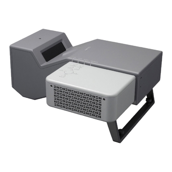
Page 9: Part Names And Functions
Part Names and Functions q Infrared Remote Receiver Front CAUTION The Infrared Remote Receiver sticks out beyond the cabinet surface. If the Infrared Remote Receiver is put on the wall or floor directly, the Infrared Remote Receiver may damage. w Top controls and Indicators e Exhaust Vent CAUTION Hot air is exhausted from the exhaust... -
Page 10: Rear Terminal
Part Names and Functions Rear Terminal q SERVICE PORT t ALARM buttons This jack is used to service the projector. Use these buttons when setting up the Alarm function (pp.55-56). w COMPUTER IN 1 y S-VIDEO IN Connect output signal from a computer, or RGB Connect the S-VIDEO output from video scart 21-pin video output to this terminal (pp.16, equipment to this jack (p.17). -
Page 11: Top
Part Names and Functions q ALARM indicator y INPUT button Blinks red to indicate the battery condition or key Select input source (pp.27 , 37 , 38). operation. u POINT ( ed7 8 ) buttons w POWER indicator – Select an item or adjust the value in the On- –... -
Page 12: Remote Control
Part Names and Functions Remote Control q ON/STAND-By button Turn the projector on or off (pp.20, 21). w VIDEO button Select VIDEO input source (pp.25, 37). e COMPUTER button Select COMPUTER input source (pp.25, 27 , 38). r MENU button Open or close the On-Screen Menu (p.22). -
Page 13: Remote Control Battery Installation
Part Names and Functions Remote Control Battery Installation Open the battery Install new batteries into Replace the compartment lid. the compartment. compartment lid. Two AA size batteries For correct polarity (+ and –), be sure battery terminals are in contact with pins in the compartment. -
Page 14: Installation
Installation Positioning the Projector For the projector positioning, see the figures below. The projector should be set perpendicularly to the plane of the screen. ✔Note: •This projector is not equipped with an optical zoom. To adjust the screen size, 0.265’ ( 8.1 cm) change the throw distance. -
Page 15: Mounting The Rear Leg And The Stand
Installation Mounting the Rear Leg and the Stand Rear Leg Turn off the projector and unplug the AC power cord. Secure the rear leg with the four (4) screws. Screw Rear leg Stand* Turn off the projector and unplug the AC power cord. Secure the stand with three (3) sets of the screw with a washer. -
Page 16: Connecting To Computer
Installation Connecting to Computer Cables used for connection • VGA Cables (Mini D-sub 15 pin)* • Audio Cables (Mini Plug: stereo) (*One cable is supplied; other cables are not supplied with the projector.) Monitor Output External Audio Equipment Monitor Output Monitor Input Audio Output Audio Input... -
Page 17: Connecting To Video Equipment (Video, S-Video)
Installation Connecting to Video Equipment (Video, S-Video) Cables used for connection • Video and Audio Cable (RCA x 3) • S-VIDEO Cable • Audio Cable (Mini Plug: stereo) (Cables are not supplied with the projector.) S-Video Output Composite Video and Audio Output External Audio Equipment (Video) Audio Input... -
Page 18: Connecting To Video Equipment (Component And Rgb Scart)
Installation Connecting to Video Equipment (Component and RGB Scart) Cables used for connection • Audio Cables (Mini Plug: stereo, RCA x 2) • Scart-VGA Cable • Component Cable (Cables are not supplied with the projector.) Component Video Output RGB Scart 21- Audio Output (Y, Pb/Cb, Pr/Cr) External Audio Equipment... -
Page 19: Connecting The Ac Power Cord
Installation Connecting the AC Power Cord This projector uses nominal input voltages of 100–120 V or 200–240 V AC and it automatically selects the correct input voltage. It is designed to work with single-phase power systems having a grounded neutral conductor. To reduce the risk of electrical shock, do not plug into any other type of power system. -
Page 20: Basic Operation
Basic Operation Turning On the Projector Complete peripheral connections (with a computer, VCR, etc.) before turning on the projector. Connect the projector’s AC power cord into an AC outlet. The POWER indicator turns red. Press the ON/STAND-BY button on the top control or on the remote control. -
Page 21: Turning Off The Projector
Basic Operation Turning Off the Projector Press the ON/STAND-BY button on the top control or on the remote control, and “Power off?” appears on the screen. Press the ON/STAND-BY button again to turn off the projector. The POWER indicator starts to blink red, and the cooling fans keep running. -
Page 22: How To Operate The On-Screen Menu
Basic Operation How to Operate the On-Screen Menu The projector can be adjusted or set via the On-Screen Top Control Menu. For each adjustment and setting procedure, refer to the respective sections in this manual. MENU button Press the MENU button on the top control or on the remote control to display the On-Screen Menu. -
Page 23: Menu Bar
Basic Operation Menu Bar For detailed functions, see Menu Tree on pages 67-68. For computer source Guide Window Image Adjust Menu Shows the selected Menu of the On-Screen Menu. Used to adjust the computer image from Contrast, Brightness, Color temp., White balance (R/G/B), Input Menu Sharpness, and Gamma (pp.34-35). -
Page 24: Zoom Adjustment
Basic Operation Top Control Zoom Adjustment ZOOM +/- buttons Press the ZOOM +/- buttons on the top control to adjust the screen size. Screen size can be adjusted 84% to 100% from its maximum screen size. It is not available when On-Screen menu is displayed. Zoom adjustment can be memorized. -
Page 25: Sound Adjustment
Basic Operation Sound Adjustment Direct Operation Top Control Volume VOLUME+/- buttons Press the VOLUME+/– buttons on the top control or on the remote control to adjust the volume. The volume dialog box appears on the screen for a few seconds. Mute Remote Control Press the MUTE button on the remote control to turn off the... - Page 26 Basic Operation Remote Control AUTO PC button Press the AUTO PC button to operate the Auto PC function. KEySTONE button VOLUME +/- (See page 24.) See page 24 for more details. buttons POINT ed (See page 25.) buttons D.ZOOM buttons AUTO PC button Press the D.ZOOM buttons to zoom in and zoom out the...
-
Page 27: Computer Input
Computer Input Input Source Selection Direct Operation Top Control INPUT button INPUT button Press the INPUT button on the top control or the COMPUTER button on the remote control to select either Computer 1 Computer 1 or Computer 2. Before using the INPUT or COMPUTER buttons, select the Computer 2* correct input source through Menu operation as described below. -
Page 28: Computer System Selection
Computer Input Computer System Selection The projector automatically tunes to various types of computers based on VGA, SVGA, XGA, SXGA, WXGA, or UXGA with its Multi-scan system and Auto PC Adjustment. If computer is selected as a signal source, the projector automatically detects the signal format and tunes to project proper images without any additional setting. -
Page 29: Auto Pc Adjustment
Computer Input Auto PC Adjustment Auto PC Adjustment function is provided to automatically adjust Fine sync, Total dots, Horizontal, and Vertical positions to conform to your computer. Direct Operation Remote Control The Auto PC adjustment function can be operated directly with the AUTO PC button on the remote control. -
Page 30: Manual Pc Adjustment
Computer Input Manual PC Adjustment Some computers employ special signal formats which may not be tuned by Multi-scan system of this projector. Manual PC Adjustment enables you to precisely adjust several parameters to match those signal formats. The projector has five independent memory areas (Mode 1–5) to store those parameters manually adjusted, which allows you to recall the setting for a specific computer. - Page 31 Computer Input Display area H Use the Point buttons to adjust the horizontal area displayed by this projector. Display area V Use the Point buttons to adjust the vertical area displayed by this projector. Reset To reset the adjusted data, select “Reset” and press the Move the red frame pointer SELECT button.
-
Page 32: Image Level Selection
Computer Input Image Level Selection Direct Operation Remote Control IMAGE button Select an image level from among Dynamic, Standard, Real, Dynamic Blackboard (Green), Colorboard, Image 1, Image 2, Image 3, or Image 4 with the IMAGE button on the remote control. Standard CEILING Dynamic... - Page 33 Computer Input Menu Operation Image Select Menu icon Image Select Menu Press the MENU button to display the On-Screen Menu. Use the Point buttons to move the red frame pointer to the Image Select Menu icon. Use the Point buttons to move the red frame Move the red frame pointer to pointer to the desired level and then press the SELECT the desired level and press the...
-
Page 34: Image Level Adjustment
Computer Input Image Level Adjustment Press the MENU button to display the On-Screen Image Adjust Menu Menu. Use the Point buttons to move the red frame pointer to the Image Adjust Menu icon. Use the Point buttons to move the red frame Image Adjust Menu icon pointer to the desired item, and then press the Move the red frame pointer... -
Page 35: Screen Size Adjustment
Computer Input Store To store the adjusted data, select “Store” and press the Move the red frame SELECT button. The Image Level Menu appears. Use the pointer to the desired image level (from Image Point buttons to choose one of the four image level and 1 to 4) and then press press the SELECT button. - Page 36 Computer Input For zooming in and out the images Remote Control Digital zoom + POINT buttons When Digital zoom + is selected, the On-Screen Menu disappears and “D. zoom +” is displayed. Press the SELECT button to expand the image size. Use the Point ed7 8 buttons to pan the image.
-
Page 37: Video Input
Video Input Input Source Selection (Video, S-Video, Component) Top Control Direct Operation INPUT button Press the INPUT button on the top control or VIDEO button on the remote control to select “Video. ” INPUT button Before using the INPUT or VIDEO buttons, select the Video correct input source through menu operation as described below. -
Page 38: Input Source Selection (Rgb Scart 21-Pin)
Video Input Input Source Selection (RGB Scart 21-pin) Direct Operation Top Control INPUT button Press the INPUT button on the top control or COMPUTER button on the remote control to select Computer 1. INPUT button Before using INPUT or COMPUTER buttons, select the Video correct input source through Menu operation as described below. -
Page 39: Video System Selection
Video Input Video System Selection Press the MENU button to display the On-Screen Menu. Use the Point buttons to move the red frame pointer to the AV System Menu icon. Use the Point buttons to move the red arrow pointer to the desired system and then press the SELECT button. -
Page 40: Image Level Selection
Video Input Image Level Selection IMAGE button Remote Control Direct Operation Dynamic Select an image level from among Dynamic, Standard, Cinema, Blackboard (Green), Colorboard, Image 1, Image 2, Image 3, and Image 4 with the IMAGE button on the Standard remote control. - Page 41 Video Input Image Select Menu Operation Menu icon Image Select Menu Use the MENU button to display the On-Screen Menu. Press the Point buttons to move the red frame pointer to the Image Select Menu icon. Use the Point buttons to move the red frame Move the red frame pointer to pointer to the desired level and then press the SELECT the desired image level and press...
-
Page 42: Image Level Adjustment
Video Input Image Level Adjustment Press the MENU button to display the On-Screen Image Adjust Menu Menu. Use the Point buttons to move the red frame pointer to the Image Adjust Menu icon. Use the Point buttons to move the red frame Image Adjust Menu icon pointer to the desired item and then press the SELECT button. - Page 43 Video Input Sharpness Press the Point button to decrease the sharpness of the image; press the Point button to increase the sharpness of the image (from 0 to 15). Gamma Use the Point buttons to adjust the gamma value to get better balance of contrast (from 0 to 15).
-
Page 44: Screen Size Adjustment
Video Input Screen Size Adjustment This projector has the picture screen resize function, which enables you to customize the image size. Press the MENU button to display the On-Screen Screen Menu Menu. Use the Point buttons to move the red frame pointer to the Screen Menu icon. -
Page 45: Setting
Setting Setting This projector has Setting menu that allows you to set up Setting Menu (Language) the other various functions described as follows: Press the MENU button to display the On-Screen Menu. Use the Point buttons to move the red Setting Menu Set the red framed frame pointer to the Setting Menu icon. - Page 46 Setting Uniformity adj. This function adjusts the brightness uniformity on a screen. Select either Store 1, Store 2 or Reset with the Point buttons, and then press the SELECT button. Press the Point buttons to adjust the brightness uniformity (from 0 to 7).
- Page 47 Setting Logo select Logo (Logo and Logo PIN code lock settings) This function allows you to customize the screen logo with Logo select, Capture, and Logo PIN code lock functions. ✔Note: • When “On” is selected in Logo PIN code lock function, Logo select and Capture functions cannot be selected.
- Page 48 Setting Logo PIN code lock Logo PIN code lock This function prevents an unauthorized person from changing the screen logo. Off…… the screen logo can be changed freely from the Logo select menu (p.47). On…… the screen logo cannot be changed without the Logo PIN code.
- Page 49 Setting Ceiling Ceiling When this function is set to “On, ” the picture is top/bottom and left/right reversed. This function is used to project the image from a ceiling-mounted projector. Rear Rear When this function is set to “On, ” the picture is left/right reversed.
- Page 50 Setting Power management Power management For reducing power consumption as well as maintaining the lamp life, the Power management function turns off the projection lamp when the input signal is interrupted and no button is pressed for a certain period. Time left before Lamp is off.
- Page 51 Setting Remote control Remote control This projector provides two different remote control codes; the factory-set, initial code (Code 1) and the secondary code (Code 2). This switching function prevents remote control interference when several projectors or video equipment Press and hold are operated at the same time.
- Page 52 Setting PIN code lock PIN code lock This function prevents the projector from being operated by unauthorized persons and provides the following setting options for security. Off…… The projector is not locked with the PIN code. On1…… Requires to enter a PIN code every time turning on the projector.
- Page 53 Setting Change the PIN code lock setting Change the PIN code lock setting Select Off, On1, or On2 with the Point buttons and then move the red frame pointer to “Quit” with the Point button. Press the SELECT button to close the dialog Select a desired setting with the box.
- Page 54 Setting Lamp Replacement icon Fig.1 Lamp replacement icon This function provides the following options in the cooling fans’ operation after turning off the projector (p.21). This icon appears on the screen when the end of L1 …… Normal operation lamp life is approaching. L2 ……...
-
Page 55: Antitheft Alarm Function
Antitheft Alarm Function How to Use the Antitheft Alarm Function Antitheft alarm function is provided to prevent the projector from being stolen. When this function is set to “On, ” the alarm rings as an unauthorized person tries to move the projector. To activate the Alarm function for the first time after purchase, you must turn on the power once. - Page 56 Antitheft Alarm Function Other settings Indicator Change the PIN code Press the F button and enter the four-digit PIN code number within about 10 seconds. The ALARM indicator blinks red for a few seconds and a high-pitched confirmation sound is produced. While the indicator is blinking, enter a new PIN code, then you will hear a high-pitched confirmation sound ALARM indicator...
- Page 57 Replace the rechargeable batteries Use only the specified battery for this projector. Using other types of battery may cause accident or fire hazard. Replacement Battery: SANYO Ni-MH BATTERY PACK Part No. 645 089 8587 How to replace the rechargeable batteries Unplug the AC power cord from a wall outlet.
- Page 58 Antitheft Alarm Function SAFETy PRECAUTIONS FOR SANyO Ni-MH BATTERy PACK Observe the following precautions when handling the built-in battery pack of the projector: ● MAKE SURE THAT THE BATTERY PACK IS INSTALLED IN THE PROJECTOR WHEN RECHARGING. USING THE CHARGERS OTHER THAN THE PROJECTOR MAY CAUSE EXPLOSION OR A FIRE.
-
Page 59: Maintenance And Cleaning
Maintenance and Cleaning Warning Indicator The WARNING indicator shows the state of the function which protects the projector. Check the state of the WARNING indicator and the POWER indicator to take proper maintenance. The projector is shut down and the WARNING indicator is blinking red. -
Page 60: Cleaning The Air Filter
Maintenance and Cleaning Cleaning the Air Filter The air filter prevents dust from accumulating on the surface of the optical elements inside the projector. Should the air filter become clogged with dust particles, it will reduce cooling fans’ effectiveness and may result in a buildup of internal heat and adversely affects the life of the projector. -
Page 61: Cleaning The Projection Window
Maintenance and Cleaning Cleaning the Projection Window CAUTION This projector is equipped with a projection window. Do not rub the projection window with a hard fiber cloth or hit it with a something hard to prevent the projection window from scratching. Do not use a chemical cleaner (liquid and solid) to avoid deteriorating the projection window. -
Page 62: Lamp Replacement
ORDER REPLACEMENT LAMP Replacement lamp can be ordered through your dealer. When ordering a projection lamp, give the following information to the dealer. Model No. of your projector : PLC-XL50 / PLC-XL50K ● Replacement Lamp Type No. : POA-LMP121 ●... -
Page 63: Lamp Replacement Counter
Maintenance and Cleaning Lamp Replacement Counter Be sure to reset the Lamp replacement counter after the lamp is replaced. When the Lamp replacement counter is reset, the LAMP REPLACE indicator stops lighting. Turn the projector on and press the MENU button to display the On-Screen Menu. -
Page 64: Appendix
Appendix Troubleshooting Before calling your dealer or service center for assistance, check the items below once again. – Make sure you have properly connected the projector to peripheral equipment as described on pages 16-18. – Make sure all equipment is connected to the AC outlet and the power is turned on. –... - Page 65 Appendix – Adjust focus of the projector (see page 24). – Provide proper distance between the projector and the projection screen (see page 14). – Check the projection window to see if it needs cleaning (see page 61). Image is out of focus. –...
- Page 66 Appendix – Check the batteries. – Make sure no obstruction is between the projector and the remote control. – Make sure you are not too far from the projector when using the remote The Remote Control does not work. control. Maximum operating range is 11.5’ (3.5 m). –...
-
Page 67: Menu Tree
Appendix Menu Tree Computer Input/Video Input Input Computer 1 Go to System RGB( Scart ) Quit Computer 2 Go to System Video Auto Go to System (2) or (3) Video Go to System S-Video Go to System Go to System Component not applicable ✽N/A... - Page 68 Appendix Video Input Setting Setting Language 16 languages provided. System Auto Quit 1080i Zoom Store 1 / Store 2 / Reset 1035i Keystone Store / Reset 720p Uniformity Adj. Store 1 / Store 2 / Reset 575p Blue back On / Off 480p Display On / Countdown off / Off...
-
Page 69: Indicators And Projector Condition
Appendix Indicators and Projector Condition Check the indicators for projector condition. For Alarm indicator, see pages 55-56. Indicators Projector Condition LAMP POWER WARNING REPLACE red/green yellow The projector is off. (The AC power cord is unplugged.) The projector is preparing for stand-by or the projection lamp is being cooled down. -
Page 70: Compatible Computer Specifications
Appendix Compatible Computer Specifications Basically this projector can accept the signal from all computers with the V-, H-Frequency mentioned below and less than 140 MHz of Dot Clock. When selecting these modes, PC adjustment can be limited. ON-SCREEN H-Freq. V-Freq. ON-SCREEN H-Freq. -
Page 71: Technical Specifications
Appendix Technical Specifications Mechanical Information Projector Type Multi-media Projector Dimensions (W x H x D) 14.72” x 7 .75” x 19.49” (374 mm x 196.8 mm x 495 mm) (Not including Rear leg) Net Weight 16.74 lbs (7 .6 kg) Feet Adjustment 0˚... -
Page 72: Optional Parts
Appendix Accessories Owner’s Manual(CD-ROM) Quick Reference Guide AC Power Cord Remote Control and Batteries VGA Cable PIN Code Label Alarm Label Lamp Replacement Label Stand ● The specifications are subject to change without notice. ● LCD panels are manufactured to the highest possible standards. Even though 99.99% of the pixels are effective, a tiny fraction of the pixels (0.01% or less) may be ineffective by the characteristics of the LCD panels. -
Page 73: Configurations Of Terminals
Ground (Blue) SERVICE PORT CONNECTOR Terminal : Mini DIN 8-PIN Serial R X D ----- ----- RTS / CTS T X D PLC-XL50 スタンド取り付け穴と 天吊り用穴4カ所共通 Dimensions Unit: inch (mm) 3.43 (87) 7.75 (196.8) 0.17 (4.2) 7.09 (180) Screw Holes for Ceiling Mount Screw: M4 Depth: 0.393 (10.0) -
Page 74: Pin Code Number Memo
Appendix PIN Code Number Memo Write down the PIN code number in the column below and keep it with this manual securely. If you forgot or lost the number and unable to operate the projector, contact the service station. PIN Code Lock No. Factory default set No: 1 2 3 4* Logo PIN Code Lock No. - Page 75 KM3A-A SANyO Electric Co., Ltd.