Table of Contents
Advertisement
Quick Links
Advertisement
Table of Contents
Troubleshooting

Related Manuals for Agilent Technologies 280-DS MQS


Summary of Contents for Agilent Technologies 280-DS MQS
- Page 1 280-DS MQS Operator’s Manual Agilent Technologies...
- Page 2 Notices Warranty © Agilent Technologies, Inc. 2013 (Technical Data) and 12.212 (Computer Software) and, for the Department of No part of this manual may be reproduced The material contained in this doc- Defense, DFARS 252.227-7015 (Techni- in any form or by any means (including ument is provided “as is,”...
-
Page 3: Table Of Contents
Contents Figures Safety Notes, Cautions, and Warnings Warning Caution Note Information Symbols Setting Up the 280-DS Introduction Unpacking Your Equipment 280-DS Components Vessel Module Instrument Module Magnetic Clip Temperature Probe Setting up the 280-DS Cable Connections Power Cord Connections Requirements and Configuration Environmental Requirements for Use PC Requirements Software Installation... - Page 4 Contents Starting 280-DS Workstation 280-DS Workstation Logon Adding Users to the Application Operating the 280-DS 280-DS Workstation Logon 280-DS Operation Dissolution Apparatus Method Editor Run Method (Method Execution) Running a Method Diagnostics Test Reports Trends Security (21 CFR Part 11 Compliance) Change User Lock Application Audit Trail...
-
Page 5: Figures
Figures Figure 1. Vessel Module Figure 2. Instrument Module Figure 3. Magnetic Clip Figure 4. Temperature Probe Figure 5. Logon Figure 6. Local Users and Groups Figure 7. Logon Figure 8. 280-DS Workstation Homescreen Figure 9. Dissolution Apparatuses Figure 10. Identification Information Figure 11. - Page 6 Figures Figure 30. Diameter Measurement Arm Lever Figure 31. Height Arm Pin Figure 32. Inserting the Vessel Module Figure 33. VM Resting at the Bottom of the Vessel Figure 34. Paddle or Basket Height Figure 35. Paddle / Basket Height Figure 36.
- Page 7 Figures Figure 63. Security Audit Trail Figure 64. Permissions Figure 65. Configuration Dialog Security Tab Figure 66. Configuration Dialog Miscellaneous Tab Figure 67. Database Tools 280-DS Operator’s Manual...
- Page 8 Figures This page was intentionally left blank, except for this message. 280-DS Operator’s Manual...
-
Page 9: Safety
If the equipment is used in a manner not specified by the manufacturer, the protection provided by the equipment may be impaired. The 280-DS MQS is operated in conjunction with equipment that uses aqueous liquids. Unskilled, improper, or careless use of this instrument... -
Page 10: Notes, Cautions, And Warnings
Safety Notes, Cautions, and Warnings Warning WA RNING A ‘Warning’ message appears in the manual when failure to observe instructions or precautions could result in death or injury. Read all warnings and cautions carefully and observe them at all times. Caution CAUTION A ‘Caution’... -
Page 11: Information Symbols
Safety Information Symbols Switches main power on Switches main power off Indicates single-phase alternating current Indicates the product complies with the requirements of one or more European Union (EU) directives. Indicates specific equipment meets standards of safety. These products are safe for use in the workplace for North America. - Page 12 Safety This page was intentionally left blank, except for this message. 280-DS Operator’s Manual...
-
Page 13: Setting Up The 280-Ds
280-DS Operator’s Manual Setting Up the 280-DS Introduction Unpacking Your Equipment 280-DS Components Setting up the 280-DS Requirements and Configuration Starting 280-DS Workstation Agilent Technologies... -
Page 14: Introduction
Setting Up the 280-DS Introduction The 280-DS Mechanical Qualification System (MQS) is a device which verifies the physical parameters of a dissolution apparatus. A Windows®-based software interface captures data from and communicates, through USB, with two hand-held modules that comprise the physical part of the device. A hand-held temperature probe also connects to the instrument module. -
Page 15: Unpacking Your Equipment
Setting Up the 280-DS Unpacking Your Equipment The 280-DS consists of the Instrument Module (IM), Vessel Module (VM), temperature probe, module intercommunication cable, USB cable, and RPM magnetic clip, all packaged in a rugged, compression-resistant case. A Windows-based PC running the 280-DS software powers and is connected to the Instrument Module (IM) with a USB cable. -
Page 16: 280-Ds Components
Setting Up the 280-DS 280-DS Components Vessel Module The Vessel Module (VM) measures rotational speed, basket/shaft wobble, vessel centering, shaft verticality, vessel verticality, and basket/paddle height. Once properly positioned, this module provides reliable, repeatable measurements using innovative sensing technology. Figure 1 Vessel Module 280-DS Operator’s Manual... -
Page 17: Instrument Module
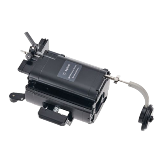
Setting Up the 280-DS Instrument Module The 280-DS Instrument Module (IM) is used to record vessel plate level and vibration while also acting as a hub for the Vessel Module, temperature probe, and connection to the PC. Quantitative values for each parameter are recorded and visible in real-time via the software interface. -
Page 18: Magnetic Clip
Setting Up the 280-DS Magnetic Clip The magnetic clip is used in conjunction with the magnetic tachometer sensor to measure RPM. Each time the magnet passes the sensor, one rotation is counted. Figure 3 Magnetic Clip Temperature Probe The temperature probe is used to verify the accuracy of the water bath and vessel temperature probes on the dissolution apparatus. -
Page 19: Setting Up The 280-Ds
Setting Up the 280-DS Setting up the 280-DS Cable Connections 1 Connect the Instrument Module of the 280-DS from the USB port on the Instrument Module to a USB port on the measurement computer. 2 Connect the 280-DS Vessel Module to the Instrument Module via the module intercommunication cable. -
Page 20: Requirements And Configuration
Setting Up the 280-DS 3 Turn on the PC and dissolution apparatus. Requirements and Configuration Environmental Requirements for Use • Humidity: max relative humidity 75% non-condensing • Indoor use only • Temperature: 10 ºC to 35 ºC PC Requirements The software is designed to run on a PC-based platform with the following minimum specifications: •... -
Page 21: Local Security Policy
Setting Up the 280-DS 1 Insert the 280-DS Workstation CD and access the files contained on the CD. 2 Execute setup.exe and follow the on-screen prompts. When asked if you want to install the Microsoft .Net Framework, you NOT E are required to click Yes. - Page 22 Setting Up the 280-DS Policy Security Setting Minimum 6 characters Password Length Password Must Enabled Meet Complexity Requirements 4 Click Security Settings > Account Policies > Account Lockout Policy. Configure the options. Policy Security Setting Account lockout 0 minutes (infinite) duration Account lockout 3 invalid login attempts...
-
Page 23: Starting 280-Ds Workstation
Setting Up the 280-DS Starting 280-DS Workstation If your operating system is Windows 7, you must log on to the computer NOT E as an administrator to set up the software and run it for the first time. Starting 280-DS Workstation 1 Double-click the 280-DS Workstation icon on the Windows desktop to start the software. -
Page 24: Adding Users To The Application
Setting Up the 280-DS Adding Users to the Application 1 After successfully logging on to the software, click Tools > Options. The Configuration Dialog screen displays. 2 To add a user to a group, select the Security tab on the Configuration Dialog screen. - Page 25 Setting Up the 280-DS 5 To add a user to a group, click Add... from the respective group screen. The Select Users, Computers, or Group screen displays. 6 Enter your user identification in the empty box and click Check Names. Ensure your user identification and domain populate the empty field.
- Page 26 Setting Up the 280-DS This page was intentionally left blank, except for this message. 280-DS Operator’s Manual...
-
Page 27: Operating The 280-Ds
280-DS Operator’s Manual Operating the 280-DS 280-DS Workstation Logon 280-DS Operation Security (21 CFR Part 11 Compliance) Agilent Technologies... -
Page 28: 280-Ds Workstation Logon
Operating the 280-DS 280-DS Workstation Logon 1 Double-click 280-DS Workstation icon. The Logon screen displays. Figure 7 Logon 2 Enter your Windows credentials in the User ID and Password boxes. 3 Verify the domain and the dissolution server are correct and click Logon. - Page 29 Operating the 280-DS The following options are available in the navigation bar on the 280-DS Workstation homescreen: Option Function Dissolution Create a file for each dissolution apparatus. All relevant data including Apparatus configuration and component serial numbers is stored within this file. See “Dissolution Apparatus”...
-
Page 30: 280-Ds Operation
Operating the 280-DS 280-DS Operation Dissolution Apparatus Click Dissolution Apparatus from the 280-DS Workstation homescreen to add or edit the dissolution apparatus being used for 280-DS test methods. Option Function Create Displays the Dissolution Apparatus editor screen to create a new dissolution apparatus entry. -
Page 31: Figure 9 Dissolution Apparatuses
Operating the 280-DS Figure 9 Dissolution Apparatuses 1 If an existing apparatus is displayed in the list, double-click the apparatus to open the Configuration Editor. When editing an existing apparatus, previously saved information displays in the fields. 2 If the list is blank, click Create to enter a new instrument. If an Agilent dissolution apparatus is connected to the computer, you NOT E can import its serial number and identification information by clicking... -
Page 32: Figure 10 Identification Information
Operating the 280-DS 3 Enter the applicable identification information for the dissolution apparatus in the provided fields. Figure 10 Identification Information Option Function Manufacturer Manufacturer of the dissolution apparatus. Serial Number Serial number associated with the dissolution apparatus. Apparatus Model Model number of the dissolution apparatus. -
Page 33: Figure 11 Dissolution Apparatus Shaft Diameters
Operating the 280-DS 4 Click Next to proceed to the next screen where you can enter the applicable shaft diameters. Figure 11 Dissolution Apparatus Shaft Diameters Option Function Default Shaft Enter the value manually and press Fill with default to fill the fields Diameter with the entered value. -
Page 34: Figure 12 Component Serial Number
Operating the 280-DS 5 Click Next to proceed to the following screen where you can record serial numbers for any attachable parts such as baskets, paddles, shafts, vessels, or spin on/off shafts. Figure 12 Component Serial Number Option Function Position Select a Position from the drop-down list (1 - 8). -
Page 35: Figure 13 Reason For Change
Operating the 280-DS 6 If you have made any changes, then upon completion of the wizard, you will be asked to explain or provide a reason for the change to comply with 21 CFR Part 11. Figure 13 Reason for Change You can click Cancel at any time and no changes will be saved. -
Page 36: Method Editor
Operating the 280-DS Method Editor From the 280-DS Workstation homescreen, click Method Editor to access the Method Editor. Figure 14 Test Methods 1 If an existing method is displayed in the list, double-click the entry to open the Method Editor. When editing a method, previously saved information displays in the fields. - Page 37 Operating the 280-DS 2 If the list is blank, click New Method to enter a new method. Option Function New Method Displays the Method Editor screen. Copy Method Prepares the selected method to be copied. Paste Copies the selected method by creating a new method with the product name of the original method with the prefix Copy of before the file name.
-
Page 38: Figure 15 Method Editor General Tab
Operating the 280-DS Method Editor General Tab 1 Double-click a method or single-click a method and click Properties to open the Method Editor. The General tap is displayed by default. Figure 15 Method Editor General Tab Option Function Method Name Enter a method name. -
Page 39: Figure 16 Specification Tab
Operating the 280-DS Method Editor Specification Tab 1 Click the Specification tab. The Specification page provides the list of available tests and fields for entering specification limits and or nominal values. Many default specifications (e.g., USP, FDA, ASTM) are available for your convenience. The pre-entered options will change and/or will be grayed out depending on your configuration. -
Page 40: Figure 17 Reason For Change
Operating the 280-DS change. After you enter a reason for the change, the method data, new or modified, is saved to the database. If you created a new method, the method version will be indicated by the number 1. If you modified a method, its version will be increased by 1 instead. -
Page 41: Run Method (Method Execution)
Operating the 280-DS Run Method (Method Execution) From the 280-DS Workstation homescreen, click Run Method to run a method. The Select Test Method screen displays and you are guided through the test procedure. Select Test Method The illustration in the figure below depicts the connection between 280-DS and PC. -
Page 42: Figure 19 Prepare The Dissolution Apparatus
Operating the 280-DS Preparing the Dissolution Apparatus Figure 19 Prepare the Dissolution Apparatus The preparation screen allows you to select either online (connected to an Agilent, Varian, or VanKel dissolution apparatus) or offline testing. 1 Select Online Testing or leave it unchecked. If Online Testing is enabled, the software will try to connect to an NOT E available dissolution apparatus. -
Page 43: Figure 20 Select The Dissolution Apparatus
Operating the 280-DS Selecting the Dissolution Apparatus 1 Select the dissolution apparatus to be measured, if applicable. 2 Click Next to continue. Figure 20 Select the Dissolution Apparatus 280-DS Operator’s Manual... -
Page 44: Figure 21 Select The 280-Ds Test Method
Operating the 280-DS Selecting Test Method The screen displays a list of available methods. 1 Select the method to be executed. 2 Click Next to continue. Figure 21 Select the 280-DS Test Method 280-DS Operator’s Manual... -
Page 45: Figure 22 Stirring Element And Vessel Positions
Operating the 280-DS Selecting the Stirring Element 1 Select the applicable stirring element for the test and check the boxes next to the positions you want to test. 2 Click Next to continue. Figure 22 Stirring Element and Vessel Positions If any of the Active Positions are unchecked, the software will notify NOT E you that the dissolution apparatus qualification record will not be... -
Page 46: Figure 23 Method Summary Tab
Operating the 280-DS Method Summary and Dissolution Assembly Summary 1 Review and/or print a report of the method and dissolution apparatus. The Method tab is displayed by default. 2 When finished, click Begin Test to begin testing. Figure 23 Method Summary Tab Figure 24 Dissolution Apparatus Tab 280-DS Operator’s Manual... -
Page 47: Running A Method
Operating the 280-DS Running a Method When you click Begin Test, the software will guide you through the NOT E sequence of tests defined within the method. See “Method Editor” on page Activity Log While running a method, an activity log is created. You can check the activity log at any time by clicking the Activity Log tab. -
Page 48: Figure 25 Im Position On Vessel Plate
Operating the 280-DS Instrument Module Position on the Vessel Plate If a vessel plate level test is required, the software prompts you to place the 280-DS Instrument Module (IM) on the vessel plate as shown in the figure below. 1 Position the IM on the vessel plate in an appropriate location. 2 Click Run to start data collection. -
Page 49: Figure 26 Vessel Plate Level Measurement
Operating the 280-DS Vessel Plate Level Measurement 1 While on the Vessel Plate Level Measurement page, you can adjust the vessel plate if it is not level. A green check mark displays on the screen if an acceptable level has been verified. 2 Click Accept to record the result. - Page 50 Operating the 280-DS Vessel Module Vessel Centering Arm Placement Ensure the manifold and evaporation covers on the dissolution CAUTION apparatus are removed prior to using the Vessel Module. Refer to the applicable section in the documentation for your dissolution apparatus for removal instructions. If any of the shaft/vessel alignment tests are required then the software prompts you to zero the encoder of the diameter arm of the Vessel Module.
-
Page 51: Figure 27 Proper Hand Position
Operating the 280-DS Figure 27 Proper Hand Position Figure 28 VM Vessel Centering Arm Placement 280-DS Operator’s Manual... -
Page 52: Figure 29 Position For Vessel Module Placement
Operating the 280-DS Vessel Module Placement Figure 29 Position for Vessel Module Placement 1 Pull back the vessel diameter arm lever and insert the Vessel Module into the dissolution vessel and position it as illustrated by the 280-DS Operator’s Manual... -
Page 53: Figure 30 Diameter Measurement Arm Lever
Operating the 280-DS software. Ensure that the height arm extension reaches the bottom of the dissolution vessel. Figure 30 Diameter Measurement Arm Lever The diameter measurement arm should be either retracted or held CAUTION manually during the insertion process. 280-DS Operator’s Manual... -
Page 54: Figure 31 Height Arm Pin
Operating the 280-DS You may need to adjust the height arm of the Vessel Module to allow for NOT E the extension to reach the bottom-center of the dissolution vessel. To adjust the travel of this arm, adjust the pin setting as shown in Figure Figure 31 Height Arm Pin 280-DS Operator’s Manual... -
Page 55: Figure 32 Inserting The Vessel Module
Operating the 280-DS 3 Slowly lower the Vessel Module into the vessel until it is seated properly. For an EaseAlign vessel, ensure that you are lowering it down into the NOT E vessel so it is oriented with the vessel diameter arm going into the DDM cutout on the EaseAlign centering ring. -
Page 56: Figure 33 Vm Resting At The Bottom Of The Vessel
Operating the 280-DS 4 Slowly release the vessel diameter arm. Push down until the underside of the top of the Vessel Module touches the top of the vessel. Ensure that the Vessel Module height arm extension is now resting at the bottom of the vessel. Figure 33 VM Resting at the Bottom of the Vessel 5 Lower the paddle or basket to the operating position. -
Page 57: Figure 34 Paddle Or Basket Height
Operating the 280-DS Paddle or Basket Height If the paddle/basket height test is required, it is the first in-vessel test to be performed. 1 To measure the height, push the height lever to move the height arm extension to the bottom of the paddle or basket. 2 Hold for a few seconds until the Accept button is available for selection and release it. -
Page 58: Figure 35 Paddle / Basket Height
Operating the 280-DS Figure 35 Paddle / Basket Height 280-DS Operator’s Manual... -
Page 59: Figure 36 Verticality And Centering Measurement
Operating the 280-DS Vessel / Shaft Verticality and Vessel Centering The following tests will be executed simultaneously on this screen: • Vessel Verticality • Shaft Verticality • Vessel / Shaft Centering (Upper and Lower) Figure 36 Verticality and Centering Measurement You can make adjustments to the dissolution apparatus at any time prior NOT E to clicking Accept to optimize the performance of the instrument. -
Page 60: Figure 37 Shaft Wobble Test Preparation
Operating the 280-DS Shaft Wobble Test Preparation After alignment is complete, the shaft wobble test begins. If the dissolution apparatus is used in Offline Mode, the prompt page NOT E instructs you to start the spindle rotation at the predefined speed. Figure 37 Shaft Wobble Test Preparation 1 Place the magnetic clip in the appropriate position as illustrated by the software. -
Page 61: Figure 38 Shaft Wobble Measurement
Operating the 280-DS Shaft Wobble Measurement The shaft wobble test measures wobble 2 cm above the paddle blade or basket over a period of 5 seconds while the spindles rotate with a predefined speed of 20 or 50 RPM. Figure 38 Shaft Wobble Measurement 1 Click Accept to store the value and continue to the next screen. -
Page 62: Figure 39 Rpm Detection Magnet Placement
Operating the 280-DS RPM Detection Magnetic Clip Placement 1 If it is not already in position after a preceding test, place the magnetic clip in the appropriate position as illustrated by the software. 2 If the dissolution apparatus is offline, you will be prompted to start the spindle rotation with an appropriate speed. -
Page 63: Figure 40 Rpm Measurement
Operating the 280-DS RPM Measurement The Rotational Speed Test measures actual RPM against the target RPM. Figure 40 RPM Measurement 1 Click Accept to store the RPM value and continue to the next screen. 280-DS Operator’s Manual... -
Page 64: Figure 41 Paddle / Basket Raise
Operating the 280-DS Paddle / Basket Shaft Removal 1 Raise the drive unit or individual shaft (if possible) to raise the paddle or basket out of the vessel. Figure 41 Paddle / Basket Raise 2 Click Next to continue to the Basket Placement for Wobble Test, if applicable. -
Page 65: Figure 42 Basket Placement For Rim Wobble Test
Operating the 280-DS Basket Rim Wobble Test (Baskets Only) 1 Position the basket rim at the level of the basket wobble sensor as illustrated by the software. If the dissolution apparatus is offline, the software also instructs you to start the spindle rotation at the pre-selected speed. -
Page 66: Figure 43 Basket Wobble Measurement
Operating the 280-DS Basket Wobble Measurement The Basket Wobble test measures the wobble at the level of the bottom rim over a period of 5 seconds while the spindles rotate with pre-selected speed of 20 or 50 RPM. 1 Click Run to start this test. Figure 43 Basket Wobble Measurement 280-DS Operator’s Manual... -
Page 67: Figure 44 Basket Rim Wobble Measurement
Operating the 280-DS Figure 44 Basket Rim Wobble Measurement 2 Click Accept to continue to the next screen. The steps previously described for VM measurements are repeated for NOT E each position specified during the method setup. See “Method Editor” on page 36 280-DS Operator’s Manual... -
Page 68: Figure 45 Completion Of The Mechanical Qualification
Operating the 280-DS Completion of the Mechanical Qualification for the Position 1 Raise the drive unit as instructed by the software. 2 Click Next to continue to the Mechanical Qualification Completion screen. Figure 45 Completion of the Mechanical Qualification 3 The Mechanical Qualification for the individual vessel position is complete. -
Page 69: Figure 46 Temperature Probe Placement
Operating the 280-DS Temperature Probe Placement 1 If the dissolution apparatus has a water bath and a probe to monitor its temperature, you will be prompted to set the temperature to the target value. If the dissolution apparatus is in the Online Mode, the temperature will be set automatically. -
Page 70: Figure 47 Bath Temperature Measurement
Operating the 280-DS Bath Temperature Measurement The Bath Temperature Measurement page displays the reading of the 280-DS temperature probe and the bath temperature reading of the dissolution apparatus, if it is online. 1 If the dissolution apparatus is offline then you have to enter the bath temperature as reported on its display. -
Page 71: Figure 48 Vessel Temperature Probe Placement
Operating the 280-DS Vessel Temperature Probe Placement 1 If the dissolution apparatus has vessel temperature probes, lower them into position. You will be prompted to wait until the temperature of the water in the vessel reaches the target value. If the dissolution apparatus is online, the temperature will be detected automatically. -
Page 72: Figure 49 Vessel Temperature Measurement
Operating the 280-DS Vessel Temperature Measurement The vessel temperature measurement page displays the reading of the 280-DS temperature probe and the vessel temperature reading of the dissolution apparatus if it is online. 1 If the dissolution apparatus is offline, enter the vessel temperature as it is displayed on its front panel or elsewhere. -
Page 73: Figure 50 Im Placement For Vibration Test
Operating the 280-DS Instrument Module Placement for Vibration If a vibration test is required, it will be the last test in the sequence. 1 The 280-DS Test tab is selected by default. Use the check boxes to run the vibration test with no spindle rotation or with the spindle rotating at 100 or 200 RPM. -
Page 74: Figure 51 Resultant Vibration Display
Operating the 280-DS Vibration Measurement The Vibration test identifies three frequencies with the highest acceleration and calculates the velocity and displacement for these frequencies. Figure 51 Resultant Vibration Display Option Function X-Axis Vibration Measures and displays vibration recorded on X-axis. Y-Axis Vibration Measures and displays vibration recorded on Y-axis. -
Page 75: Figure 52 Successful Update Mq Record
Operating the 280-DS 1 Click Accept to store the vibration values and continue to the next screen. The software will continue to guide you through all selected speeds. Successful Update Physical Parameters 1 Upon completion of the test sequence: • If the method has the Update Qualification Record option selected (“Update Qualification Record”... -
Page 76: Figure 53 Unsuccessful Update Mq Record
Operating the 280-DS 2 Click Complete to update the physical parameters and display the Method Completion screen. Figure 53 Unsuccessful Update MQ Record 3 You can cancel the method any time by clicking Cancel. Before exiting the method run, you will be required to provide an explanation or reason for the cancellation. -
Page 77: Figure 54 Method Cancelling
Operating the 280-DS Figure 54 Method Cancelling When the test is complete, the report is compiled and displayed on screen. See “Test Reports” on page 280-DS Operator’s Manual... -
Page 78: Diagnostics
Operating the 280-DS Diagnostics Current Status Tab Click Diagnostics from the 280-DS homescreen to access software diagnostics. When you select Diagnostics, the software automatically connects to the 280-DS if it is present and live data streams are initiated. Figure 55 Current Status Tab 280-DS Operator’s Manual... -
Page 79: Figure 56 Advanced Tab
Operating the 280-DS Advanced Tab The Advanced tab provides advanced diagnostic features for the Instrument Module and Vessel Module and displays the values coming from the connected 280-DS modules. From this tab, you can start and stop the stream of data, change the rate of collection, switch between full precision (no calibrated data values applied), and raw data (normal operation) modes. -
Page 80: Figure 57 Vibration Tab
Operating the 280-DS Vibration Tab When you select the Vibration tab, the vibration data stream from 280-DS Instrument Module starts and other measurement data streams from Vessel Module and Instrument Module stop. This allows you to stop and restart the vibration data in order to take a snapshot of the data. Figure 57 Vibration Tab The vibration data can be recorded and replayed. -
Page 81: Figure 58 Module Information Tab
Operating the 280-DS Module Information Tab When you select the Module Information tab, Instrument Module and Vessel Module manufacturing and calibration data is downloaded from the devices. Each device can hold up to 20 previous calibration records. Figure 58 Module Information Tab If one of an Agilent dissolution apparatus is connected to the same PC, it can be controlled from the software through the dialog box. -
Page 82: Test Reports
Operating the 280-DS Test Reports Click Test Reports from the 280-DS Workstation homescreen to set up and access reports. Various filtering criteria is available to display the desired test reports stored in the database. Report Selection • Date range (inclusive), tester serial number, for operator, laboratory •... -
Page 83: Figure 59 Reports
Operating the 280-DS Figure 59 Reports Option Function Filter Testing data / results reports can be displayed based on date range, dissolution apparatus serial number, 280-DS module, operator, laboratory, due date, report status, test ID, and test status by selecting the applicable option and clicking Filter. -
Page 84: Figure 60 Show Result
Operating the 280-DS Show Report When you double-click a row in the table, the results report displays. The results report consists of a compliance Mechanical Qualification Report Sheet and detailed report. Figure 60 Show Result Option Function Sign Select to electronically sign the report. You will have to enter your User ID and Password to sign the report. -
Page 85: Trends
Operating the 280-DS Show Report Options Check the box next to the data to be displayed on each report (Show Report Sheet, Show Detailed Report, Show Run Log). Verify Report Integrity To verify report Integrity, return to the 280-DS Workstation homescreen and click Test Reports... -
Page 86: Figure 62 Mq Measurements Trends
Operating the 280-DS For each test, the overall trending and per-position trending is displayed. Figure 62 MQ Measurements Trends 280-DS Operator’s Manual... -
Page 87: Security (21 Cfr Part 11 Compliance)
Operating the 280-DS Security (21 CFR Part 11 Compliance) Change User 1 To change the current user account logged in to the software, click Change User from the 280-DS Workstation homescreen. 2 Enter login information and click Logon. Lock Application 1 To lock the application, click Lock Application from the 280-DS Workstation homescreen. -
Page 88: Audit Trail
Operating the 280-DS Audit Trail Click Audit Trail from the 280-DS Workstation homescreen to access the Security Audit Trail screen. Figure 63 Security Audit Trail Option Function Show Report Creates a detailed report of Security Audit Trail activity based on the date range specified. -
Page 89: Permissions
Operating the 280-DS Permissions Review the permissions granted to the current user. Figure 64 Permissions 280-DS Operator’s Manual... -
Page 90: Tools
Operating the 280-DS Tools Configuration Dialog Select Tools > Options from the 280-DS Workstation homescreen to display the Configuration Dialog screens. Figure 65 Configuration Dialog Security Tab Option Function User Groups Review the permissions granted to each user group. User Modify the permissions granted to each user and/or group. - Page 91 Operating the 280-DS Figure 66 Configuration Dialog Miscellaneous Tab Option Function Use Simulated Runs the software in a simulation mode where the 280-DS modules do Instruments not have to be connected. No official data is acquired in this mode. Idle Minutes Amount of time before the software locks automatically.
- Page 92 Operating the 280-DS Database Tools Select Tools > Database from the 280-DS Workstation to display the Database Tools screens. Figure 67 Database Tools Option Function Dissolution Server Name of the dissolution server where the database is located. Integrated Allows you to assume responsibility for administrating database access. Security Change DB Updates the current settings of the database.
-
Page 93: Troubleshooting And Maintenance
280-DS Operator’s Manual Troubleshooting and Maintenance Preventive Maintenance Troubleshooting Agilent Technologies... -
Page 94: Preventive Maintenance
Troubleshooting and Maintenance Preventive Maintenance Recalibration The 280-DS is calibrated to standards when the instrument is assembled. Agilent recommends a recalibration interval of 12 months under normal usage within the dissolution laboratory. To keep the instrument at optimum performance within the calibration period, please refer to the following information: •... -
Page 95: Troubleshooting
Troubleshooting and Maintenance Troubleshooting See “Diagnostics” on page 78 for basic troubleshooting. NOT E The following is a troubleshooting guide which may help you with common problems. For other problems, please contact your local Customer Care Center. Contact information can be found at www.agilent.com under your country using the Contact Us link. - Page 96 Troubleshooting and Maintenance Symptom Probable Cause Suggested Solution Can’t connect to the The dissolution apparatus is not • Contact Agilent to update the dissolution apparatus. supported (i.e., non-Agilent/ firmware on the apparatus (if Varian/VanKel) or the firmware possible). version on the dissolution apparatus is not supported.
- Page 97 Troubleshooting and Maintenance Symptom Probable Cause Suggested Solution Cannot perform functions User does not have proper • Administrator must add desired user within the software (e.g., rights/access to desired to individual Vk groups to grant create system/method, run function. access/privileges to specific software method, etc.).
- Page 98 Troubleshooting and Maintenance This page was intentionally left blank, except for this message. 280-DS Operator’s Manual...
-
Page 99: Service And Warranty
280-DS Operator’s Manual Service and Warranty Service and Warranty Information Agilent Technologies... -
Page 100: Service And Warranty Information
Service and Warranty Service and Warranty Information The warranty is provided by Agilent Technologies, Inc. or one of its authorized representatives. Obtaining Warranty and Other Services To place a service order (warranty or other services), please contact your local Customer Care Center. Contact information can be found at www.agilent.com under your country using the Contact Us link. -
Page 101: Index
Index Numerics Current Status Tab, Method Editor, 29, General Tab, 21 CFR Part 11 Compliance, Specification Tab, 280-DS Method Name, Database Server, Components, Method Summary, Database Tools, Operation, Module Information Tab, Workstation Logon, 23, Default Shaft Diameter, MQ Completion, Delete, 30, 34, Diagnostics, 29, Dissolution Apparatus, 29, Activity Log,... - Page 102 Index Report, 30, Tools, Report Selection, Trends, 29, Require Comments on Failed Troubleshooting, Measurements, Requirements and Configuration, Restore, unpacking your equipment, 13, Resultant, Use Simulated Instruments, Retrieve Records, User Administration, RPM Detection, User Groups, RPM Measurement, Run Method, 29, Running a Method, Verify, Verify Integrity, 30, Vessel...