
Related Manuals for Nokia RH-99


Summary of Contents for Nokia RH-99
- Page 1 Nokia Customer Care Service Manual RH-99; RH-100; RH-105; RH-106 (Nokia 1200; Nokia 1208) Mobile Terminal Part No: 9200070 (Issue 2) COMPANY CONFIDENTIAL Copyright © 2007 Nokia. All rights reserved.
- Page 2 RH-99; RH-100; RH-105; RH-106 Amendment Record Sheet Amendment Record Sheet Amendment No Date Inserted By Comments Issue 1 05/2007 Y Liu Issue 2 11/2007 Y Liu Service Tools updated Page ii COMPANY CONFIDENTIAL Issue 2 Copyright © 2007 Nokia. All rights reserved.
- Page 3 Nokia operates a policy of continuous development. Nokia reserves the right to make changes and improvements to any of the products described in this document without prior notice. Under no circumstances shall Nokia be responsible for any loss of data or income or any special, incidental, consequential or indirect damages howsoever caused.
- Page 4 WCDMA networks and cause problems to 3G cellular phone communication in a wide area. • During testing never activate the GSM or WCDMA transmitter without a proper antenna load, otherwise GSM or WCDMA PA may be damaged. Page iv COMPANY CONFIDENTIAL Issue 2 Copyright © 2007 Nokia. All rights reserved.
- Page 5 Use only approved accessories and batteries. Do not connect incompatible products. CONNECTING TO OTHER DEVICES When connecting to any other device, read its user’s guide for detailed safety instructions. Do not connect incompatible products. Issue 2 COMPANY CONFIDENTIAL Page v Copyright © 2007 Nokia. All rights reserved.
- Page 6 All of the above suggestions apply equally to the product, battery, charger or any accessory. Page vi COMPANY CONFIDENTIAL Issue 2 Copyright © 2007 Nokia. All rights reserved.
- Page 7 RH-99; RH-100; RH-105; RH-106 ESD protection ESD protection Nokia requires that service points have sufficient ESD protection (against static electricity) when servicing the phone. Any product of which the covers are removed must be handled with ESD protection. The SIM card can be replaced without ESD protection if the product is otherwise ready for use.
- Page 8 Batteries' performance is particularly limited in temperatures well below freezing. Do not dispose of batteries in a fire! Dispose of batteries according to local regulations (e.g. recycling). Do not dispose as household waste. Page viii COMPANY CONFIDENTIAL Issue 2 Copyright © 2007 Nokia. All rights reserved.
- Page 9 Our policy is of continuous development; details of all technical modifications will be included with service bulletins. While every endeavour has been made to ensure the accuracy of this document, some errors may exist. If any errors are found by the reader, NOKIA MOBILE PHONES Business Group should be notified in writing/e- mail. Please state: •...
- Page 10 RH-99; RH-100; RH-105; RH-106 Company Policy (This page left intentionally blank.) Page x COMPANY CONFIDENTIAL Issue 2 Copyright © 2007 Nokia. All rights reserved.
- Page 11 RH-99; RH-100; RH-105; RH-106 Nokia 1200; Nokia 1208 Service Manual Structure Nokia 1200; Nokia 1208 Service Manual Structure 1 General information 2 Service Tools 3 FPC's Disassembly and reassembly instructions 4 Baseband troubleshooting 5 RF troubleshooting 6 System module Glossary...
- Page 12 RH-99; RH-100; RH-105; RH-106 Nokia 1200; Nokia 1208 Service Manual Structure (This page left intentionally blank.) Page xii COMPANY CONFIDENTIAL Issue 2 Copyright © 2007 Nokia. All rights reserved.
- Page 13 Nokia Customer Care 1 — General information Issue 2 COMPANY CONFIDENTIAL Page 1 –1 Copyright © 2007 Nokia. All rights reserved.
- Page 14 RH-99; RH-100; RH-105; RH-106 General information (This page left intentionally blank.) Page 1 –2 COMPANY CONFIDENTIAL Issue 2 Copyright © 2007 Nokia. All rights reserved.
-
Page 15: Table Of Contents
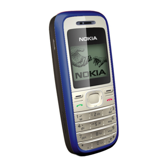
Table 3 Audio ................................1–7 Table 4 Normal and extreme voltages .........................1–9 Table 5 Current consumption..........................1–10 List of Figures Figure 1 The product picture of RH-99/100 and RH-105/106 ................1–5 Issue 2 COMPANY CONFIDENTIAL Page 1 –3 Copyright © 2007 Nokia. All rights reserved. - Page 16 RH-99; RH-100; RH-105; RH-106 General information (This page left intentionally blank.) Page 1 –4 COMPANY CONFIDENTIAL Issue 2 Copyright © 2007 Nokia. All rights reserved.
-
Page 17: Product Selection
General information Product selection The RH-99/105 is the EU version of the telephone with a dual band transceiver unit designed for the GSM900 and GSM1800 networks. The RH-100/106 is the US version of the telephone with a dual band transceiver unit designed for the GSM850 and GSM1900 networks. -
Page 18: Software Features
• Automatic answer (works with headset or car kit only) • Call waiting, call hold, call divert, and call timer • Automatic and manual network selection • Vibrating alert Voice features • Integrated handsfree speaker Page 1 –6 COMPANY CONFIDENTIAL Issue 2 Copyright © 2007 Nokia. All rights reserved. -
Page 19: Mobile Enhancements
• Phone Features • Demo application accessible both with and without SIM mode. • Speaking clock & speaking alarm • Prepaid tracker (network dependent service) Mobile enhancements Mobile enhancements for RH-99/100 and RH-105/106 Table 1 Power Type Name BL-5C Battery 1020 mAh Li-Ion... -
Page 20: Technical Specifications
No storage. An attempt to operate <-40 C and >+85 storage may cause permanent damage Charging allowed C ... +55 Long term storage C ... +85 conditions Page 1 –8 COMPANY CONFIDENTIAL Issue 2 Copyright © 2007 Nokia. All rights reserved. -
Page 21: Electrical Characteristics
4.60 might appear for a short while. d. The minimum battery cell voltage required for the reset circuitry to turn on. This is not confirmed by measures at pt. Issue 2 COMPANY CONFIDENTIAL Page 1 –9 Copyright © 2007 Nokia. All rights reserved. -
Page 22: Table 5 Current Consumption
RH-99; RH-100; RH-105; RH-106 General information Table 5 Current consumption Condition Typical Unit Call (MoU) GSM 850 (E)GSM 900 GSM 1800 GSM 1900 Idle (MoU) Power off µA Page 1 –10 COMPANY CONFIDENTIAL Issue 2 Copyright © 2007 Nokia. All rights reserved. - Page 23 Nokia Customer Care 2 — Service Tools Issue 2 COMPANY CONFIDENTIAL Page 2 –1 Copyright © 2007 Nokia. All rights reserved.
- Page 24 RH-99; RH-100; RH-105; RH-106 Service Tools (This page left intentionally blank.) Page 2 –2 COMPANY CONFIDENTIAL Issue 2 Copyright © 2007 Nokia. All rights reserved.
-
Page 25: Table Of Contents
Figure 4 FPS-10 Prommer box flash concept ....................2–16 Figure 5 JBV-1 flash concept with FPS-10 ......................2–17 Figure 6 JBV-1 flash concept with FPS-8......................2–18 Issue 2 COMPANY CONFIDENTIAL Page 2 –3 Copyright © 2007 Nokia. All rights reserved. - Page 26 RH-99; RH-100; RH-105; RH-106 Service Tools Figure 7 Module jig service concept ........................2–19 Page 2 –4 COMPANY CONFIDENTIAL Issue 2 Copyright © 2007 Nokia. All rights reserved.
-
Page 27: Service Tools
RH-99; RH-100; RH-105; RH-106 Service Tools Service tools The table below gives a short overview of service tools that can be used for testing, error analysis and repair of product RH-99; RH-100; RH-105; RH-106, refer to various concepts. ACF-8 Universal power supply ACF-8 universal power supply is used to power FPS-8. - Page 28 USB cable The CA-31D USB cable is used to connect FPS-10 or FPS-11 to a PC. It is included in the FPS-10 and FPS-11 sales packages. Page 2 –6 COMPANY CONFIDENTIAL Issue 2 Copyright © 2007 Nokia. All rights reserved.
- Page 29 Features include: • compatible with the JBV-1 • easy phone attachment and detachment. • reliable phone locking • switch for detecting phone • replaceable SIM interface Issue 2 COMPANY CONFIDENTIAL Page 2 –7 Copyright © 2007 Nokia. All rights reserved.
-
Page 30: Dau-9S
FLS-5 is a dongle and flash device incorporated into one package, developed specifically for POS use. Note: FLS-5 can be used as an alternative to PKD-1. Page 2 –8 COMPANY CONFIDENTIAL Issue 2 Copyright © 2007 Nokia. All rights reserved. - Page 31 FPS-8 from the universal power supply, ACF-8. The sales pack includes: • FPS-8 flash prommer • FPS-8 activation sheet • ACF-8 universal power supply • AXS-4 service cable (D9-D9) • Printer cable Issue 2 COMPANY CONFIDENTIAL Page 2 –9 Copyright © 2007 Nokia. All rights reserved.
- Page 32 PCS-1 Power cable The PCS-1 power cable (DC) is used with a docking station, a module jig or a control unit to supply a controlled voltage. Page 2 –10 COMPANY CONFIDENTIAL Issue 2 Copyright © 2007 Nokia. All rights reserved.
- Page 33 Its bottom part is a rubber. SF-56 POS flash adapter The POS flash adapter SF-56 allows FBUS/MBUS connections for flashing. Its bottom part is a clip. Issue 2 COMPANY CONFIDENTIAL Page 2 –11 Copyright © 2007 Nokia. All rights reserved.
- Page 34 PWB. The jig is made of EDS proof material. ST-30 Rework stencil It is used together with RJ-51 to rework the Front End Module (FEM) N7700. Page 2 –12 COMPANY CONFIDENTIAL Issue 2 Copyright © 2007 Nokia. All rights reserved.
- Page 35 The RF cable is used to connect, for example, a module repair jig to the RF measurement equipment. SMA to N-Connector approximately 610 mm. Attenuation for: • GSM850/900: 0.3+-0.1 dB • GSM1800/1900: 0.5+-0.1 dB • WLAN: 0.6+-0.1dB Issue 2 COMPANY CONFIDENTIAL Page 2 –13 Copyright © 2007 Nokia. All rights reserved.
-
Page 36: Service Software Concept
Figure 2 POS flash concept Item Description Type Phone Battery Easy flash cable II CA-111DS FLS-4S sales pack FLS-4S AC charger ACF-8 PC with Service SW CD-ROM Page 2 –14 COMPANY CONFIDENTIAL Issue 2 Copyright © 2007 Nokia. All rights reserved. -
Page 37: Pos Flash Concept With Fls-5
RH-99; RH-100; RH-105; RH-106 Service Tools POS flash concept with FLS-5 Figure 3 POS flash concept with FLS-5 Issue 2 COMPANY CONFIDENTIAL Page 2 –15 Copyright © 2007 Nokia. All rights reserved. -
Page 38: Fps-10 Prommer Box Flash Concept
Flash prommer box sales pack FPS-10 Power supply, included in FPS-10 sales package AFC-8 USB A to B cable CA-31D Software protection key PKD-1 Service SW (PHOENIX) Page 2 –16 COMPANY CONFIDENTIAL Issue 2 Copyright © 2007 Nokia. All rights reserved. -
Page 39: Flash Concept With Fps-10
Figure 5 JBV-1 flash concept with FPS-10 Item Description Type Docking station JBV-1 Docking station adapter DA-49 DC power cable CA-41PS Modular cable XCS-4 Flash prommer box sales pack FPS-10 Issue 2 COMPANY CONFIDENTIAL Page 2 –17 Copyright © 2007 Nokia. All rights reserved. -
Page 40: Flash Concept With Fps-8
Figure 6 JBV-1 flash concept with FPS-8 Item Description Type Docking station JBV-1 Docking station adapter DA-49 DC power cable PCS-1 Modular cable XCS-4 Flash prommer box sales pack FPS-8 Page 2 –18 COMPANY CONFIDENTIAL Issue 2 Copyright © 2007 Nokia. All rights reserved. -
Page 41: Module Jig (Mj-130) Service Concept
Software protection key PKD-1 Service SW (PHOENIX) Module jig (MJ-130) service concept Figure 7 Module jig service concept Item Description Type Module jig MJ-130 RF test cable XCF-4 Issue 2 COMPANY CONFIDENTIAL Page 2 –19 Copyright © 2007 Nokia. All rights reserved. - Page 42 RH-99; RH-100; RH-105; RH-106 Service Tools Item Description Type Service MBUS/FBUS cable DAU-9S DC power cable PCS-1 Software protection key PKD-1 PC with Service SW (PHOENIX) Page 2 –20 COMPANY CONFIDENTIAL Issue 2 Copyright © 2007 Nokia. All rights reserved.
- Page 43 Nokia Customer Care 3 — FPC's Disassembly and reassembly instructions Issue 2 COMPANY CONFIDENTIAL Page 3 –1 Copyright © 2007 Nokia. All rights reserved.
- Page 44 RH-99; RH-100; RH-105; RH-106 FPC's Disassembly and reassembly instructions (This page left intentionally blank.) Page 3 –2 COMPANY CONFIDENTIAL Issue 2 Copyright © 2007 Nokia. All rights reserved.
- Page 45 RH-99; RH-100; RH-105; RH-106 FPC's Disassembly and reassembly instructions Table of Contents Result of mating/ unmating test of BtoB connector ..................3–5 Mating/ unmating method of BtoB connector ....................3–5 Issue 2 COMPANY CONFIDENTIAL Page 3 –3 Copyright © 2007 Nokia. All rights reserved.
- Page 46 RH-99; RH-100; RH-105; RH-106 FPC's Disassembly and reassembly instructions (This page left intentionally blank.) Page 3 –4 COMPANY CONFIDENTIAL Issue 2 Copyright © 2007 Nokia. All rights reserved.
- Page 47 RH-99; RH-100; RH-105; RH-106 FPC's Disassembly and reassembly instructions Result of mating/ unmating test of BtoB connector Mating/ unmating method of BtoB connector Issue 2 COMPANY CONFIDENTIAL Page 3 –5 Copyright © 2007 Nokia. All rights reserved.
- Page 48 RH-99; RH-100; RH-105; RH-106 FPC's Disassembly and reassembly instructions (This page left intentionally blank.) Page 3 –6 COMPANY CONFIDENTIAL Issue 2 Copyright © 2007 Nokia. All rights reserved.
- Page 49 Nokia Customer Care 4 — Baseband troubleshooting Issue 2 COMPANY CONFIDENTIAL Page 4 –1 Copyright © 2007 Nokia. All rights reserved.
- Page 50 RH-99; RH-100; RH-105; RH-106 Baseband troubleshooting (This page left intentionally blank.) Page 4 –2 COMPANY CONFIDENTIAL Issue 2 Copyright © 2007 Nokia. All rights reserved.
- Page 51 ................4–18 Figure 27 Earpiece fault flow chart ........................4–18 Figure 28 IHF/ring tone fault flow chart ......................4–19 Figure 29 Microphone fault flow chart......................4–20 Issue 2 COMPANY CONFIDENTIAL Page 4 –3 Copyright © 2007 Nokia. All rights reserved.
- Page 52 RH-99; RH-100; RH-105; RH-106 Baseband troubleshooting (This page left intentionally blank.) Page 4 –4 COMPANY CONFIDENTIAL Issue 2 Copyright © 2007 Nokia. All rights reserved.
-
Page 53: General Baseband Troubleshooting
Possible failures could be short-circuit of balls under µBGAs (UEMCLite, UPP, FLASH). Missing or misaligned components. In flash programming error cases the flash prommer can give some information about a fault. The fault information messages could be: Issue 2 COMPANY CONFIDENTIAL Page 4 –5 Copyright © 2007 Nokia. All rights reserved. - Page 54 Because of the use of uBGA components it is not possible to verify if there is a short circuit in control- and address lines of MCU (UPP) and memory (flash). Figure 9 Flash programming fault Page 4 –6 COMPANY CONFIDENTIAL Issue 2 Copyright © 2007 Nokia. All rights reserved.
-
Page 55: Phone Doesn't Switch On
It is assumed that the voltage supplied is 3.6VDC. The UEMCLite/Litti will prevent any functionality at battery/supply levels below 2.9VDC. Figure 10 Troubleshooting when the phone doesn't switch on Issue 2 COMPANY CONFIDENTIAL Page 4 –7 Copyright © 2007 Nokia. All rights reserved. -
Page 56: Switch Off
It's individual test cases so the below lineup of error hunting's has no chronological order. Use common sense and experience to decide which test case to start error hunting at. Page 4 –8 COMPANY CONFIDENTIAL Issue 2 Copyright © 2007 Nokia. All rights reserved. -
Page 57: The Phone Does Not Register To The Networks, Or The Phone Can Not Make A Call
First of all verify that SIM LOCK is not the reason to cause phone cannot connect to network. The way is to check if the phone can connect to CMU200 by a test SIM card. Issue 2 COMPANY CONFIDENTIAL Page 4 –9 Copyright © 2007 Nokia. All rights reserved. -
Page 58: Sim Related Faults
SIM card. When the power is switched on the phone first check for a 1.8V SIM card and then a 3V SIM card. The phone will try this four times, where after it will display ”Insert SIM card”. Page 4 –10 COMPANY CONFIDENTIAL Issue 2 Copyright © 2007 Nokia. All rights reserved. -
Page 59: Sim Card Rejected
The first data is always ATR and it is sent from card to phone. For reference a picture with normal SIM power-up is shown below. Issue 2 COMPANY CONFIDENTIAL Page 4 –11 Copyright © 2007 Nokia. All rights reserved. -
Page 60: User Interface
The display does not show any information at all. Figure 17 Blank display Display is corrupt The display contains missing or fading segments or color presentation is incorrect. Page 4 –12 COMPANY CONFIDENTIAL Issue 2 Copyright © 2007 Nokia. All rights reserved. -
Page 61: Dead Keys
One or more keys don't function at all. Figure 19 Dead keys No backlight for display or keys Troubleshooting flow There is no backlight on the display or on the keys. Issue 2 COMPANY CONFIDENTIAL Page 4 –13 Copyright © 2007 Nokia. All rights reserved. - Page 62 RH-99; RH-100; RH-105; RH-106 Baseband troubleshooting Figure 20 No backlight for display or keys Page 4 –14 COMPANY CONFIDENTIAL Issue 2 Copyright © 2007 Nokia. All rights reserved.
-
Page 63: Audio Troubleshooting
RH-99; RH-100; RH-105; RH-106 Baseband troubleshooting Audio troubleshooting Audio troubleshooting using phoenix Troubleshooting flow Figure 21 Phoenix audio test window Issue 2 COMPANY CONFIDENTIAL Page 4 –15 Copyright © 2007 Nokia. All rights reserved. -
Page 64: Check Microphone Using "Hp Microphone In Ext Speaker Out" Loop
6. Check if signal is detected at XEarL/R pads, shown in Figure 23 Test arrangement for microphone Check earpiece using "Ext microphone in Hp speaker out" loop Steps 1. Connect phone with Phoenix. Page 4 –16 COMPANY CONFIDENTIAL Issue 2 Copyright © 2007 Nokia. All rights reserved. -
Page 65: Check Ihf Function Using "Ext Microphone In Ihf Speaker Out" Loop
Check vibra function using "Vibra control" Steps 1. Connect phone with Phoenix. 2. Open “Vibra control” window from “Testing -> Vibra control”, as shown in the figure below. Issue 2 COMPANY CONFIDENTIAL Page 4 –17 Copyright © 2007 Nokia. All rights reserved. -
Page 66: Earpiece Fault
5. Click “Write”. 6. Check if Vibra works. Figure 26 Checking vibra function by using vibra control Earpiece fault Troubleshooting flow Figure 27 Earpiece fault flow chart Page 4 –18 COMPANY CONFIDENTIAL Issue 2 Copyright © 2007 Nokia. All rights reserved. -
Page 67: Ihf/Ringing Tone Fault
RH-99; RH-100; RH-105; RH-106 Baseband troubleshooting IHF/ringing tone fault Troubleshooting flow Figure 28 IHF/ring tone fault flow chart Issue 2 COMPANY CONFIDENTIAL Page 4 –19 Copyright © 2007 Nokia. All rights reserved. -
Page 68: Microphone Fault
RH-99; RH-100; RH-105; RH-106 Baseband troubleshooting Microphone fault Troubleshooting flow Figure 29 Microphone fault flow chart Page 4 –20 COMPANY CONFIDENTIAL Issue 2 Copyright © 2007 Nokia. All rights reserved. - Page 69 Nokia Customer Care 5 — RF troubleshooting Issue 2 COMPANY CONFIDENTIAL Page 5 –1 Copyright © 2007 Nokia. All rights reserved.
- Page 70 RH-99; RH-100; RH-105; RH-106 RF troubleshooting (This page left intentionally blank.) Page 5 –2 COMPANY CONFIDENTIAL Issue 2 Copyright © 2007 Nokia. All rights reserved.
-
Page 71: List Of Figures
Figure 42 GSM 1900 Receiver troubleshooting ....................5–17 Figure 43 Measurement points at the RX SAW Filters – Z7101/Z7100 ............5–18 Figure 44 GSM 900 RF controls window ......................5–19 Issue 2 COMPANY CONFIDENTIAL Page 5 –3 Copyright © 2007 Nokia. All rights reserved. - Page 72 Figure 73 TXP signal............................5–38 Figure 74 TXC signals at PCL0 ..........................5–39 Figure 75 TXC signals at PCL15 ........................... 5–39 Figure 76 Crystal output signal waveform......................5–40 Page 5 –4 COMPANY CONFIDENTIAL Issue 2 Copyright © 2007 Nokia. All rights reserved.
-
Page 73: General Rf Troubleshooting
FEM(PA & Antenna Switch) D7402 Uppcosto Z7101 EGSM850/900 RX SAW filter Z7100 DCS1800/PCS1900 RX SAW filter Z7102 EGSM850/900 TX filter D2901 Litti B7402 26 MHz crystal Issue 2 COMPANY CONFIDENTIAL Page 5 –5 Copyright © 2007 Nokia. All rights reserved. - Page 74 VC1 signal measured at Test Point TP7103 VC2 signal measured at Test Point TP7102 VC3 signal measured at Test Point TP7101 VPC signal measured at Test Point R7112 Page 5 –6 COMPANY CONFIDENTIAL Issue 2 Copyright © 2007 Nokia. All rights reserved.
-
Page 75: Auto Tuning
Steps 1. Make sure the phone (in the jig) is connected to the equipment. Else, some menus will not be shown in Phoenix. Issue 2 COMPANY CONFIDENTIAL Page 5 –7 Copyright © 2007 Nokia. All rights reserved. -
Page 76: Receiver Gsm900/1800
Active Unit: RX ii Band: GSM 900 iii Operation Mode: Continuous mode iv RX/TX Channel 37 AGC: Gain 6 Results The setup should now look like this: Page 5 –8 COMPANY CONFIDENTIAL Issue 2 Copyright © 2007 Nokia. All rights reserved. - Page 77 RH-99; RH-100; RH-105; RH-106 RF troubleshooting Figure 34 GSM900 RF controls window Issue 2 COMPANY CONFIDENTIAL Page 5 –9 Copyright © 2007 Nokia. All rights reserved.
-
Page 78: Troubleshooting Diagram For Gsm 900 Receiver
RH-99; RH-100; RH-105; RH-106 RF troubleshooting Troubleshooting diagram for GSM 900 receiver Troubleshooting flow Page 5 –10 COMPANY CONFIDENTIAL Issue 2 Figure 35 GSM 900 Receiver troubleshooting Copyright © 2007 Nokia. All rights reserved. -
Page 79: General Instructions For Gsm 1800 Rx Troubleshooting
Operation Mode: Continuous mode iv RX/TX Channel 700 AGC: Gain 6 Results The setup should now look like this: Figure 36 GSM1800 RF controls window Issue 2 COMPANY CONFIDENTIAL Page 5 –11 Copyright © 2007 Nokia. All rights reserved. -
Page 80: Troubleshooting Diagram For Gsm 1800 Receiver
RH-99; RH-100; RH-105; RH-106 RF troubleshooting Troubleshooting diagram for GSM 1800 receiver Figure 37 GSM 1800 Receiver troubleshooting Page 5 –12 COMPANY CONFIDENTIAL Issue 2 Copyright © 2007 Nokia. All rights reserved. -
Page 81: Measurement Points In The Receiver
Active Unit: RX ii Band: GSM 850 iii Operation Mode: Continuous mode iv RX/TX Channel 190 AGC: Gain 6 Results The setup should now look like this: Issue 2 COMPANY CONFIDENTIAL Page 5 –13 Copyright © 2007 Nokia. All rights reserved. - Page 82 RH-99; RH-100; RH-105; RH-106 RF troubleshooting Figure 39 GSM850 RF controls window Page 5 –14 COMPANY CONFIDENTIAL Issue 2 Copyright © 2007 Nokia. All rights reserved.
-
Page 83: Troubleshooting Diagram For Gsm 850 Receiver
RH-99; RH-100; RH-105; RH-106 RF troubleshooting Troubleshooting diagram for GSM 850 receiver Figure 40 GSM 850 Receiver troubleshooting Issue 2 COMPANY CONFIDENTIAL Page 5 –15 Copyright © 2007 Nokia. All rights reserved. -
Page 84: General Instructions For Gsm1900 Rx Troubleshooting
Operation Mode: Continuous mode iv RX/TX Channel 661 AGC: Gain 6 Results The setup should now look like this: Figure 41 GSM 1900 RF controls window Page 5 –16 COMPANY CONFIDENTIAL Issue 2 Copyright © 2007 Nokia. All rights reserved. -
Page 85: Troubleshooting Diagram For Gsm 1900 Receiver
RH-99; RH-100; RH-105; RH-106 RF troubleshooting Troubleshooting diagram for GSM 1900 receiver Figure 42 GSM 1900 Receiver troubleshooting Issue 2 COMPANY CONFIDENTIAL Page 5 –17 Copyright © 2007 Nokia. All rights reserved. -
Page 86: Measurement Points In The Receiver
6. Set the parameters as follows: Band: GSM 900 ii Active Unit: TX iii TX Power Level: 5 iv TX Data Type: Random Results The setup should now look like this: Page 5 –18 COMPANY CONFIDENTIAL Issue 2 Copyright © 2007 Nokia. All rights reserved. - Page 87 RH-99; RH-100; RH-105; RH-106 RF troubleshooting Figure 44 GSM 900 RF controls window Issue 2 COMPANY CONFIDENTIAL Page 5 –19 Copyright © 2007 Nokia. All rights reserved.
-
Page 88: Troubleshooting Diagram For Gsm 900 Transmitter
RH-99; RH-100; RH-105; RH-106 RF troubleshooting Troubleshooting diagram for GSM 900 transmitter Troubleshooting Flow Figure 45 GSM900 transmitter troubleshooting diagram Page 5 –20 COMPANY CONFIDENTIAL Issue 2 Copyright © 2007 Nokia. All rights reserved. -
Page 89: Gsm900 Tx Output Power
Measure the output power of the phone; it should be about 32.5dBm. Remember the cable loss is about 0.3dB. Figure 46 VC1 signal Figure 47 VC2 signal Issue 2 COMPANY CONFIDENTIAL Page 5 –21 Copyright © 2007 Nokia. All rights reserved. - Page 90 RH-99; RH-100; RH-105; RH-106 RF troubleshooting Figure 48 VC3 signal Figure 49 TXP signal Page 5 –22 COMPANY CONFIDENTIAL Issue 2 Copyright © 2007 Nokia. All rights reserved.
- Page 91 RH-99; RH-100; RH-105; RH-106 RF troubleshooting Figure 50 TXC signals at PCL5 Figure 51 TXC signals at PCL19 Issue 2 COMPANY CONFIDENTIAL Page 5 –23 Copyright © 2007 Nokia. All rights reserved.
-
Page 92: General Instructions For Gsm1800 Tx Troubleshooting
Active Unit: TX iii TX Power Level: 0 iv TX Data Type: Random Results The setup should now look like this: Figure 52 GSM 1800 RF controls window Page 5 –24 COMPANY CONFIDENTIAL Issue 2 Copyright © 2007 Nokia. All rights reserved. -
Page 93: Troubleshooting Diagram For Gsm 1800 Transmitter
Figure 53 GSM 1800 Transmitter troubleshooting GSM1800 TX output power Measure the output power of the phone; it should be about 29.5dBm. Remember the cable loss is about 0.5dB. Issue 2 COMPANY CONFIDENTIAL Page 5 –25 Copyright © 2007 Nokia. All rights reserved. - Page 94 RH-99; RH-100; RH-105; RH-106 RF troubleshooting Figure 54 VC1 signal Figure 55 VC2 signal Page 5 –26 COMPANY CONFIDENTIAL Issue 2 Copyright © 2007 Nokia. All rights reserved.
- Page 95 RH-99; RH-100; RH-105; RH-106 RF troubleshooting Figure 56 VC3 signal Figure 57 TXP signal Issue 2 COMPANY CONFIDENTIAL Page 5 –27 Copyright © 2007 Nokia. All rights reserved.
- Page 96 RH-99; RH-100; RH-105; RH-106 RF troubleshooting Figure 58 TXC signals at PCL0 Figure 59 TXC signals at PCL15 Page 5 –28 COMPANY CONFIDENTIAL Issue 2 Copyright © 2007 Nokia. All rights reserved.
-
Page 97: Transmitter Gsm850/1900
6. Set the parameters as follows: Band: GSM 850 ii Active Unit: TX iii TX Power Level: 5 iv TX Data Type: Random Results The setup should now look like this: Issue 2 COMPANY CONFIDENTIAL Page 5 –29 Copyright © 2007 Nokia. All rights reserved. - Page 98 RH-99; RH-100; RH-105; RH-106 RF troubleshooting Figure 60 GSM 850 RF controls window Page 5 –30 COMPANY CONFIDENTIAL Issue 2 Copyright © 2007 Nokia. All rights reserved.
-
Page 99: Troubleshooting Diagram For Gsm 850 Transmitter
RH-99; RH-100; RH-105; RH-106 RF troubleshooting Troubleshooting diagram for GSM 850 transmitter Troubleshooting flow Figure 61 GSM 850 transmitter troubleshooting Issue 2 COMPANY CONFIDENTIAL Page 5 –31 Copyright © 2007 Nokia. All rights reserved. -
Page 100: Gsm850 Tx Output Power
Measure the output power of the phone; it should be about 32.5dBm. Remember the cable loss is about 0.3dB. Figure 62 VC1 signal Figure 63 VC2 signal Page 5 –32 COMPANY CONFIDENTIAL Issue 2 Copyright © 2007 Nokia. All rights reserved. - Page 101 RH-99; RH-100; RH-105; RH-106 RF troubleshooting Figure 64 VC3 signal Figure 65 TXP signal Issue 2 COMPANY CONFIDENTIAL Page 5 –33 Copyright © 2007 Nokia. All rights reserved.
- Page 102 RH-99; RH-100; RH-105; RH-106 RF troubleshooting Figure 66 TXC signals at PCL5 Figure 67 TXC signals at PCL19 Page 5 –34 COMPANY CONFIDENTIAL Issue 2 Copyright © 2007 Nokia. All rights reserved.
-
Page 103: General Instructions For Gsm1900 Tx Troubleshooting
Active Unit: TX iii TX Power Level: 0 iv TX Data Type: Random 7. The setup should now look like this: Figure 68 GSM 1900 RF controls window Issue 2 COMPANY CONFIDENTIAL Page 5 –35 Copyright © 2007 Nokia. All rights reserved. -
Page 104: Troubleshooting Diagram For Gsm 1900 Transmitter
Figure 69 GSM 1900 transmitter toubleshooting GSM1900 TX output power Measure the output power of the phone; it should be about 29.5dBm. Remember the cable loss is about 0.5dB. Page 5 –36 COMPANY CONFIDENTIAL Issue 2 Copyright © 2007 Nokia. All rights reserved. - Page 105 RH-99; RH-100; RH-105; RH-106 RF troubleshooting Figure 70 VC1 signal Figure 71 VC2 signal Issue 2 COMPANY CONFIDENTIAL Page 5 –37 Copyright © 2007 Nokia. All rights reserved.
- Page 106 RH-99; RH-100; RH-105; RH-106 RF troubleshooting Figure 72 VC3 signal Figure 73 TXP signal Page 5 –38 COMPANY CONFIDENTIAL Issue 2 Copyright © 2007 Nokia. All rights reserved.
- Page 107 RH-99; RH-100; RH-105; RH-106 RF troubleshooting Figure 74 TXC signals at PCL0 Figure 75 TXC signals at PCL15 Issue 2 COMPANY CONFIDENTIAL Page 5 –39 Copyright © 2007 Nokia. All rights reserved.
-
Page 108: Crystal Troubleshooting
The 26 MHz signal from the crystal can be measured by probing C7436. The level at this point is approx. 276mVpp. Example Signal Measured at VCXO output (C7436). Figure 76 Crystal output signal waveform Page 5 –40 COMPANY CONFIDENTIAL Issue 2 Copyright © 2007 Nokia. All rights reserved. - Page 109 Nokia Customer Care 6 — System module Issue 2 COMPANY CONFIDENTIAL Page 6 –1 Copyright © 2007 Nokia. All rights reserved.
- Page 110 RH-99; RH-100; RH-105; RH-106 System module (This page left intentionally blank.) Page 6 –2 COMPANY CONFIDENTIAL Issue 2 Copyright © 2007 Nokia. All rights reserved.
- Page 111 Figure 81 Keyboard schematics ......................... 6–11 Figure 82 SIM interface block diagram......................6–13 Figure 83 BL-5CA battery block .......................... 6–13 Figure 84 PWB top side component placement ....................6–14 Issue 2 COMPANY CONFIDENTIAL Page 6 –3 Copyright © 2007 Nokia. All rights reserved.
- Page 112 RH-99; RH-100; RH-105; RH-106 System module (This page left intentionally blank.) Page 6 –4 COMPANY CONFIDENTIAL Issue 2 Copyright © 2007 Nokia. All rights reserved.
-
Page 113: Block Diagram
UPPCosto includes 2MBit internal RAM, ARM7 Thumb 16/32-bit RISC MCU core, LEAD3 16-bit DSP core, ROM for MCU boot code and all digital control logic. UPPCosto also contains the major part of the RF system. Issue 2 COMPANY CONFIDENTIAL Page 6 –5 Copyright © 2007 Nokia. All rights reserved. -
Page 114: Litti
• Charging: Charging can be performed in any operating mode. Audio function description Audio The basic audio structure and communication between HW-audio modules and the audio ASIC's is illustrated in the block diagram below. Page 6 –6 COMPANY CONFIDENTIAL Issue 2 Copyright © 2007 Nokia. All rights reserved. -
Page 115: External Audio Connector
Jack plug, which is integrated in the system connector, contains a mechanical switch, which is used to detect the connection of the accessories. The configuration for the 4-pole Jack-plug is shown in the following figure. Issue 2 COMPANY CONFIDENTIAL Page 6 –7 Copyright © 2007 Nokia. All rights reserved. -
Page 116: External Signals And Connections
XEARN External earphone signal output Accessory detection Ground (Only used by PPH-1) External signals and connections Table 7 System connector Signal XMICIN XEARN XMICP XEARP HEADINT Page 6 –8 COMPANY CONFIDENTIAL Issue 2 Copyright © 2007 Nokia. All rights reserved. -
Page 117: Interfaces
LCD interface The display is controlled by phone processor UPPcosto. The LCD module is connected to the PWB by a flex PWB with 10-pin BtB connector. Issue 2 COMPANY CONFIDENTIAL Page 6 –9 Copyright © 2007 Nokia. All rights reserved. -
Page 118: Keyboard
A 5 X 4 matrix keyboad consists of 20 keys, one 10-channel integrated passive filiter arrays with downstream ESD protection of >8KV connect the matrix keyboard to UPPcosto. The layout is shown in Keyboard layout in UI side. Page 6 –10 COMPANY CONFIDENTIAL Issue 2 Copyright © 2007 Nokia. All rights reserved. - Page 119 RH-99; RH-100; RH-105; RH-106 System module Figure 81 Keyboard schematics Issue 2 COMPANY CONFIDENTIAL Page 6 –11 Copyright © 2007 Nokia. All rights reserved.
-
Page 120: Sim Interface
SIM data (input) 1.8V Vil 0.15xVSIM Trise/Tfall max 3V Vil 0.7xVSI VSIM 3V Vil 0.15xVSIM Not connected Ground VSIM specified in regulator section in this document Page 6 –12 COMPANY CONFIDENTIAL Issue 2 Copyright © 2007 Nokia. All rights reserved. -
Page 121: Battery Connector
PWB, opposite to the Battery. Battery pack has an impedance of 130 - 150 mΩ (0 – 45 °C). Figure 83 BL-5CA battery block Issue 2 COMPANY CONFIDENTIAL Page 6 –13 Copyright © 2007 Nokia. All rights reserved. -
Page 122: Pwb Outline
TX data are feed into two points of the ADPLL. The GMSK modulated output signal of the ADPLL block are fed into Pre-Power Amplifier (PPA) buffer. Page 6 –14 COMPANY CONFIDENTIAL Issue 2 Copyright © 2007 Nokia. All rights reserved. -
Page 123: Digitally Controlled X-Tal Oscillator
The Digitally Controlled X-tal Oscillator (DCXO) provides the reference clock for the DRP2 and for the digital baseband. The only external component is the crystal (and a series capacitor). Issue 2 COMPANY CONFIDENTIAL Page 6 –15 Copyright © 2007 Nokia. All rights reserved. - Page 124 RH-99; RH-100; RH-105; RH-106 System module (This page left intentionally blank.) Page 6 –16 COMPANY CONFIDENTIAL Issue 2 Copyright © 2007 Nokia. All rights reserved.
- Page 125 Nokia Customer Care Glossary Issue 2 COMPANY CONFIDENTIAL Page Glossary–1 Copyright © 2007 Nokia. All rights reserved.
- Page 126 RH-99; RH-100; RH-105; RH-106 Glossary (This page left intentionally blank.) Page Glossary–2 COMPANY CONFIDENTIAL Issue 2 Copyright © 2007 Nokia. All rights reserved.
- Page 127 Clock Timing Sleep and interrupt block of Tiku Continuous wave D/A-converter Digital-to-analogue converter Digital-to-analogue converter Digital Battery Interface DBus DSP controlled serial bus connected between UPP_WD2 and Helgo DCT-4 Digital Core Technology Issue 2 COMPANY CONFIDENTIAL Page Glossary–3 Copyright © 2007 Nokia. All rights reserved.
- Page 128 High speed circuit switched data (data transmission connection faster than GSM) Hardware Input/Output IBAT Battery current Integrated circuit ICHAR Charger current Interface Integrated hands free IMEI International Mobile Equipment Identity Infrared IrDA Infrared Data Association Page Glossary–4 COMPANY CONFIDENTIAL Issue 2 Copyright © 2007 Nokia. All rights reserved.
- Page 129 General Purpose IO (PIO), USARTS and Pulse Width Modulators PURX Power-up reset Printed Wiring Board Pulse width modulation RC-filter Resistance-Capacitance filter Radio Frequency RF PopPort™ Reduced function PopPort™ interface RFBUS Serial control Bus For RF Issue 2 COMPANY CONFIDENTIAL Page Glossary–5 Copyright © 2007 Nokia. All rights reserved.
- Page 130 Communicator version of DCT4 system ASIC Universal Serial Bus VBAT Battery voltage VCHAR Charger voltage Voltage controlled oscillator VCTCXO Voltage Controlled Temperature Compensated Crystal Oscillator VCXO Voltage Controlled Crystal Oscillator Page Glossary–6 COMPANY CONFIDENTIAL Issue 2 Copyright © 2007 Nokia. All rights reserved.
- Page 131 Wideband code division multiple access Watchdog WLAN Wireless local area network XHTML Extensible hypertext markup language Zocus Current sensor (used to monitor the current flow to and from the battery) Issue 2 COMPANY CONFIDENTIAL Page Glossary–7 Copyright © 2007 Nokia. All rights reserved.
- Page 132 RH-99; RH-100; RH-105; RH-106 Glossary (This page left intentionally blank.) Page Glossary–8 COMPANY CONFIDENTIAL Issue 2 Copyright © 2007 Nokia. All rights reserved.