Table of Contents
Advertisement
Quick Links
Advertisement
Table of Contents

Related Manuals for RedMax CHTZ60


Summary of Contents for RedMax CHTZ60
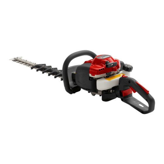
- Page 1 Workshop manual CHTZ60 English 1351 - 002 - 25.11.2020...
-
Page 2: Table Of Contents
Contents 1 Introduction 1.1 Document description..........3 1.2 Target group............3 1.3 Revisions..............3 1.4 Safety..............3 1.5 Servicing tools............3 2 Safety 2.1 Safety definitions............4 2.2 General safety instructions........4 2.3 Symbols on the product......... 4 3 Prepare and do servicing on the product 3.1 Maintenance schedule........... -
Page 3: Introduction
1.5 Servicing tools The manual gives information about necessary servicing tools. Always use original tools from RedMax. 1351 - 002 - 25.11.2020 Introduction - 3... -
Page 4: Safety
2 Safety 2.1 Safety definitions Warnings, cautions and notes are used to point out Always wear approved protective gloves. specially important parts of the manual. WARNING: Used if there is a risk of injury or death for the operator or bystanders if the Use stable boots with non-slip soles. -
Page 5: Prepare And Do Servicing On The Product
3 Prepare and do servicing on the product 3.1 Maintenance schedule Maintenance Before After 100 After 40 h operation Clean the external surface. After each operation. Clean the muffler, exhaust pipe and engine from leaves, dirt and unwanted lubri- After each operation. cant. -
Page 6: Servicing Data
4 Servicing data 4.1 Servicing data ▲ Lubricate with 2-stroke oil. ● Lubricate with grease. 3 - 4 Nm 3 - 4 Nm 2 - 3 Nm 3 - 4 Nm 5 - 8 Nm 3 - 4.5 Nm 1.5 - 2.5 Nm 2 - 3 Nm 3 - 4.5 Nm 6 - Servicing data... - Page 7 6 - 8 Nm 3 - 5 Nm 6 - 9 Nm 4 - 6 Nm 10 - 15 Nm 6 - 9 Nm 8 mm 1351 - 002 - 25.11.2020 Servicing data - 7...
- Page 8 4 - 6 Nm 3 - 4 Nm 6 - 8 Nm 8 - 10 Nm 10 - 12 Nm 16 mm 6 - 8 Nm 2.5 - 3 Nm 1.5 - 2.5 Nm 4.5 - 5.5 Nm 3 - 4 Nm 10 - 12 Nm 8 - Servicing data 1351 - 002 - 25.11.2020...
- Page 9 6 - 9 Nm 6 - 9 Nm 8 mm 8 mm 6 - 9 Nm 8 mm 6 - 9 Nm 8 mm 6 - 9 Nm 3 - 5 Nm 3 - 5 Nm 1351 - 002 - 25.11.2020 Servicing data - 9...
-
Page 10: Servicing Tools
5 Servicing tools 5.1 Servicing tools 10 - Servicing tools 1351 - 002 - 25.11.2020... - Page 11 Item Description Article number Removal tool for To remove ball bearings. 502 50 18-01 the ball bearing T-handle Torx, To loosen or remove Torx screws. 502 71 27-02 Carburetor ad- To adjust the idle speed screw on the carburetor. 501 60 02-03 justment tool Carburetor ad- To adjust the high speed needle and low speed needle on the carbu-...
-
Page 12: Function Overview
6 Function overview 6.1 Type plate and product serial number RedMax CHTZXXXX s/n 20XX XXXXXXX XXX XX XX-XX Husqvarna AB Huskvarna, Sweden 12 - Function overview 1351 - 002 - 25.11.2020... -
Page 13: Repair Instructions
7 Repair instructions 7.1 Product overview for repair instructions 1. Starter unit 6. Air filter 2. Muffler 7. Fuel tank 3. Spark plug 8. Carburetor 4. Flywheel 9. Rear handle 5. Ignition module 10. Gearbox 1351 - 002 - 25.11.2020 Repair instructions - 13... -
Page 14: To Clean And Examine The Product Parts
11. Cutting equipment 7.3.2 To disassemble the starter unit 12. Cylinder and piston WARNING: Use protective glasses. The recoil 13. Crankcase and crankshaft spring can eject from the starter pulley and 14. Front handle cause injury. 7.2 To clean and examine the product parts To remove and 1. - Page 15 4. Remove the screw (A), the drive disc (B), and the 7.3.4 To install the recoil spring in the starter pulley drive disc spring (C). WARNING: Use protective glasses. The recoil spring can eject from the starter pulley and cause injury. 1.
- Page 16 7.3.5 To assemble the starter unit 8. Lubricate the drive disc spring with cold resistant grease. 1. Make sure that the recoil spring is installed in the starter pulley. Install the recoil spring if it is 9. Install the drive disc (D). To install the recoil spring in the necessary.
-
Page 17: Muffler
2. Examine the spark arrester for damage. 4. Put the air filter and 1 tablespoon of air filter oil in a plastic bag. Use RedMax air filter oil. Refer to 3. Examine the muffler and the muffler holder for Servicing tools on page 10 . -
Page 18: Flywheel
5. Rub the plastic bag to supply the air filter oil equally CAUTION: Make sure that the piston stop across the air filter. does not go into the exhaust port. There is a risk of engine damage. 5. Remove the nut. 6. - Page 19 • Make sure that the key in the flywheel and keyway 4. Put the flywheel in position on the crankshaft. are not damaged. • Clean the crankshaft from grease and oil. 7.6.3 To assemble the flywheel 1. Make sure that the key in the flywheel and the keyway in the crankshaft are not damaged.
-
Page 20: Ignition System
7.7 Ignition system 5. Remove the spark plug and connect the ignition Servicing tools tester to the spark plug cap. Refer to on page 10 . 7.8 Introduction The engine has an electronic ignition system fully without moving parts. A defective component cannot be repaired, but must be replaced by a new component. - Page 21 7.8.3 To do a test of the short circuit cable 7.8.5 To examine the spark plug cable 1. Disconnect the short circuit cables. If there is no spark, do the procedure that follows to examine the connection between the spark plug cable and the spark plug.
- Page 22 4. Put the end of the cable against the stop of the 8. Push the cable into the spark plug cap. Servicing tools on page 10 . assembly pliers, refer to Then close the pliers to make the new hole. 9.
-
Page 23: Carburetor
To remove and install 3. Examine the connections for damage, dirt, and 10. Install the starter unit. Refer to the starter unit on page 14 . corrosion. 7.8.7 To remove and install the ignition module To remove and 1. Remove the starter unit. Refer to install the starter unit on page 14 . - Page 24 4. Carefully remove the 2 screws, the air filter holder 8. Make a note of how the fuel hoses (H) and (I) are (A), and the gasket (B). connected. 9. Disconnect the fuel hoses and remove the carburetor. 10. Install in the opposite sequence. 7.9.2 To disassemble and assemble the carburetor To remove and 1.
- Page 25 6. Examine the needle valve lever and the needle 10. Assemble in the opposite sequence. Make sure that valve for wear and damages. the needle valve lever is level with the surface of the carburetor housing. 7. Carefully remove the check valve (J) from the valve housing (K).
- Page 26 5. Make sure that there are no leaks. 4. Remove the 4 screws, the intake manifold, and the intake manifold gasket. 7.9.4 To adjust the carburetor To adjust the carburetor means that you adjust the engine to the local conditions such as weather, altitude and fuel.
-
Page 27: Handles
7.10 Handles 3. Remove the 2 screws (A) and the 4 washers (B). 7.10.1 To remove and install the front handle 1. Remove the 2 screws (A), the 2 washers (B), the 2 vibration elements (C), and the front handle (D). 2. - Page 28 7.10.3 To disassemble and assemble the throttle 3. Push up the flange (D) with a small screwdriver and remove the handle holder (E) from the throttle handle handle (F). To remove and 1. Remove the throttle handle. Refer to install the throttle handle on page 27 . 2.
- Page 29 6. Carefully remove the left throttle handle half. 10. Make a note of the position of the recoil spring. 7. Remove the safety catch (G) and the spring (H). 8. Make a note of the position of the throttle cable. 11.
-
Page 30: Cutting Unit
7.10.4 To remove and install the stop switch 3. Remove the 3 screws (A). 1. Use a flat screwdriver to loosen the stop switch. 2. Disconnect the 2 cables. 3. Remove the stop switch. 4. Remove the 2 screws (B). 5. - Page 31 7. Use the clutch removal tool to remove the clutch. 3. Remove the 6 screws and remove the gearbox Servicing The clutch has a left hand thread. Refer to cover. Use a flat screwdriver if it is necessary. tools on page 10 . 8.
- Page 32 4. Remove the gasket (A). 16. Assemble in the opposite sequence. 17. Add approximately 10 g of grease to the gearbox. 7.12.3 To remove and install the clutch drum To disassemble 1. Disassemble the gearbox. Refer to and assemble the gearbox on page 31 . 2.
-
Page 33: Cylinder And Piston
• Examine the clutch and the clutch springs for 7.13.2 To remove the cylinder and piston damages. To remove and 1. Remove the starter unit. Refer to install the starter unit on page 14 . 7.13 Cylinder and piston To remove and 2. - Page 34 9. Remove the cylinder cover. 11. Remove the 2 screws, the cylinder, and the cylinder gasket. 10. Remove the heat shield. 12. Put a cloth above the crankcase opening below the piston. 34 - Repair instructions 1351 - 002 - 25.11.2020...
- Page 35 13. Remove the snap rings on the piston pin with a 16. Remove the piston ring, if it is necessary. small flat nose pliers. Hold your finger on the snap ring to make sure it does not eject. 7.13.3 To clean and examine the cylinder and piston CAUTION: Clean carefully.
- Page 36 • Use a screwdriver to remove dirt particles from the • Put the piston ring in the cylinder and measure the cooling fins. space with an air gap tool. The space must not be more than 1 mm. • Clean all parts. •...
- Page 37 • Clean and examine the piston ring groove. It must 7.13.6 To assemble the cylinder and piston not be more than 1.6 mm. 1. Lubricate the needle bearing with two-stroke oil and put it into the connecting rod. Make sure that the needle bearing moves freely in the connecting rod.
-
Page 38: Crankshaft And Crankcase
5. Put a new cylinder base gasket on the crankcase. 7. Use the clamp from the piston assembly kit to compress the piston ring. Carefully push the piston into the cylinder opening. Tighten the 2 screws to Servicing data on page the specified torque. - Page 39 7.14.2 To disassemble the crankcase and 4. Use a screwdriver or equivalent to remove the sealing ring on each crankcase half. crankshaft 1. Remove the 3 screws and disconnect the crankcase CAUTION: Remove the sealing rings halves. carefully. The crankcase is easily damaged. a) Flywheel side.
- Page 40 a) Flywheel side. 7. Increase the temperature of the crankcase halves to 120ºC with a hot air gun. 8. Use the removal tool for the ball bearings to remove the ball bearings from the crankcase halves. a) Flywheel side. b) Clutch side. 40 - Repair instructions 1351 - 002 - 25.11.2020...
- Page 41 b) Clutch side. • Examine the crankshaft bearing. There must be no radial play in the connecting rod. Make sure that there is axial play to sufficiently lubricate the crankshaft bearing. • Examine the crankcase halves for cracks and damages. 7.14.4 To assemble the crankcase and crankshaft 1.
- Page 42 b) Clutch side. b) Clutch side. 3. Put the sealing ring in the crankcase half on the flywheel side. 2. Put the ball bearing in the crankcase. Carefully tap the removal tool for the ball bearing, refer to Servicing tools on page 10 , with a rubber hammer until the ball bearing is in position.
- Page 43 4. Put the crankshaft in the crankcase half on the 5. Install the gasket to the clutch side of the crankcase flywheel side. Lubricate the stub axle with some half. Lubricate the crankshaft pin with some drops of drops of oil and carefully move the crankshaft into oil and move the crankcase half on the clutch side the ball bearing.
-
Page 44: Fuel Tank
6. Put an assembly sleeve on the crankshaft on the 4. Remove the transparent fuel hose (A) from the clutch side to prevent damage to the sealing ring. carburetor and connect it to the pressure tester. Lubricate the crankshaft with oil and install the sealing ring. - Page 45 4. Remove the fuel hoses from the fuel tank. 6. Put the fuel filter in the tank as shown in the illustration. 5. Install in the opposite sequence. 7.15.3 To clean and examine the fuel filter 1. Remove the fuel tank cap. 2.
-
Page 46: Troubleshooting
8 Troubleshooting 8.1 Troubleshooting Starting The engine is hard to start The stop screw for the throttle does not operate correctly Blocked fuel filter Blocked fuel hose Air in fuel pipes Incorrect/unsatisfactory fuel The needle valve is defective The lever arm of the needle valve is damaged The lever arm of the needle valve does not operate correctly The control diaphragm is damaged The control diaphragm has a defective seal... - Page 47 Idle speed (low speed) The idle speed does not become The stop screw for the throttle does not operate correctly stable Blocked fuel filter Blocked fuel hose Air in fuel pipes Incorrect/unsatisfactory fuel The needle valve is defective The carburetor is not attached correctly The lever arm of the needle valve does not operate correctly The needle valve spring is not attached correctly The control diaphragm is damaged...
- Page 48 High speed Unsatisfactory performance at Blocked fuel filter high speed Blocked fuel hose Air in fuel pipes Incorrect/unsatisfactory fuel Vacuum pulse leakage Blocked vacuum pulse pipe Loose screws on the pump cover Defective pump diaphragm The needle valve is defective The carburetor is not attached correctly The lever arm of the needle valve is damaged The lever arm of the needle valve does not operate correctly...
- Page 49 Increasing and decreasing speed Can not increase speed Defective heat insulation seal 1351 - 002 - 25.11.2020 Troubleshooting - 49...
-
Page 50: Technical Data
9 Technical data 9.1 Technical data CHTZ60 Engine Cylinder displacement, cm 21.7 Idle speed, rpm 2900 Recommended max speed, rpm 9000 Maximum engine power acc. to ISO 8893, kW/hp @ rpm 0.6/0.8 @ 7800 Catalytic converter muffler Ignition system Spark plug... - Page 51 1351 - 002 - 25.11.2020 Technical data - 51...
- Page 52 114 19 79-26 2020-12-01...