
Related Manuals for Emerson Rosemount 2051G


Summary of Contents for Emerson Rosemount 2051G
- Page 1 Reference Manual 00809-0400-4101, Rev BA January 2018 ™ Rosemount 2051G In-Line Pressure Transmitter ® with HART Revision 5 and 7 Selectable Protocol...
-
Page 3: Table Of Contents
Models covered ............1 1.2.1 Rosemount 2051G In-Line Gage Pressure Transmitter ....1 1.2.2 Rosemount 2051G In-Line Absolute Pressure Transmitter . - Page 4 Contents Reference Manual 00809-0100-4016, Rev RF January 2018 2.12.1Verifying alarm level ..........21 2.12.2Performing an analog loop test .
- Page 5 Reference Manual Contents 00809-0100-4016, Rev RF January 2018 5Section 5: Operation and Maintenance Overview ............45 Safety messages .
- Page 6 7.6.4 Rosemount 2051G SIS reference ........68 7.6.5...
- Page 7 The products described in this document are NOT designed for nuclear-qualified applications. Using non-nuclear qualified products in applications that require nuclear-qualified hardware or products may cause inaccurate readings. For information on Rosemount nuclear-qualified products, contact your local Emerson Sales Representative. Title Page...
- Page 8 Installation of this transmitter in an explosive environment must be in accordance with the appropriate local, national, and international standards, codes, and practices. Review the approvals section of the Rosemount 2051G Reference Manual for any restrictions associated with a safe installation.
-
Page 9: Using This Manual
™ Rosemount 2051G. The sections are organized as follows: Section 2: Configuration provides instruction on commissioning and operating Rosemount 2051G Transmitters. Information on software functions, configuration parameters, and online variables is also included. Section 3: Hardware Installation contains mechanical installation instructions, and field upgrade options. - Page 10 Introduction Reference Manual 00809-0400-4101, Rev BA January 2018 Introduction...
-
Page 11: Safety Messages
Reference Manual Configuration 00809-0300-4410, Rev BA January 2018 Section 2 Configuration Safety messages ..............page 3 System readiness . -
Page 12: System Readiness
Installation of this transmitter in an explosive environment must be in accordance with the appropriate local, national, and international standards, codes, and practices. Review the approvals section of the Rosemount 2051G Reference Manual for any restrictions associated with a safe installation. - Page 13 Reference Manual Configuration 00809-0300-4410, Rev BA January 2018 Table 2-1. Device Revisions and Files Review Identify device Find device driver files Review instructions functionality Software NAMUR NAMUR HART HART release hardware software software universal Device Manual document Changes to date revision revision revision...
-
Page 14: Hart Installation Flowchart
Configuration Reference Manual 00809-0300-4410, Rev BA January 2018 HART installation flowchart Figure 2-1. HART Installation Flowchart START HERE Bench Calibration? Field Install Configure Security and Configure for Alarm Verify Pressure (page Mount Transmitter Set Units Review Transmitter page 29 page 13 Configuration page 9 Check Process... -
Page 15: Transmitter Overview
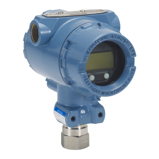
The Rosemount 2051G utilizes piezoresistive sensor technology for AP and GP measurements. The major components of the Rosemount 2051G In-Line are the sensor module and the electronics housing.The sensor module contains the oil filled sensor system (isolating diaphragm, oil fill system and sensor). - Page 16 Configuration Reference Manual 00809-0300-4410, Rev BA January 2018 Figure 2-3. Block Diagram Of Operation Signal Processing Microprocessor Digital-to- • Sensor Module Sensor linearization Analog Signal • Rerange Memory Conversion Temp. • Damping • Sensor Diagnostics • Engineering units • Communication Digital Pressure Communication...
-
Page 17: Configuration Overview
Set all transmitter hardware adjustments during commissioning to avoid exposing the transmitter electronics to the plant environment after installation. The Rosemount 2051G can be configured either before or after installation. Configuring the transmitter on the bench using either a Field Communicator, AMS Device Manager, or LOI ensures all transmitter components are in working order prior to installation. -
Page 18: Configuration Tools
Device Dashboard interface. As stated in System readiness , it is critical that the latest DD’s are loaded into the Field Communicator. Visit Emerson.com FieldCommGroup.org to download latest DD library. Field Communicator menu trees and Fast Keys are available in... -
Page 19: Setting The Loop To Manual
Field Communicator is located Appendix B: Field Communicator Menu Trees and Fast Keys. Fast key sequences for the latest DD are shown in Table 2-3. For Fast Key sequences for legacy DD's contact your local Emerson Representative. Configuration... -
Page 20: Ams Device Manager
Configuration Reference Manual 00809-0300-4410, Rev BA January 2018 Table 2-3. Device Dashboard Fast Key Sequence From the HOME screen, enter the Fast Key sequences listed Fast Key sequence Function HART 7 HART 5 Alarm and Saturation Levels 2, 2, 2, 5 2, 2, 2, 5 Damping 2, 2, 1, 1, 5... -
Page 21: Basic Setup Of The Transmitter
Reference Manual Configuration 00809-0300-4410, Rev BA January 2018 Basic setup of the transmitter This section provides the necessary steps for basic setup of a pressure transmitter. When installing in DP level or DP flow applications, refer to “Configuring scaled variable” on page 19 for setup instructions. - Page 22 Configuration Reference Manual 00809-0300-4410, Rev BA January 2018 Manually rerange the transmitter by entering range points Field Communicator From the HOME screen, enter the Fast Key sequence Device Dashboard Fast Keys 2, 2, 2, 1 AMS Device Manager 1. Right click the device and select Configure. 2.
- Page 23 Reference Manual Configuration 00809-0300-4410, Rev BA January 2018 Figure 2-9. Rerange with Applied Pressure Using LOI RERANGE VIEW CONFIG ENTER VALUES ZERO TRIM APPLY VALUES APPLY VALUES APPLY VALUES UNITS RERANGE RERANGE BACK TO MENU EXIT MENU LOOP TEST BACK TO MENU DISPLAY EXIT MENU EXTENDED MENU...
-
Page 24: Damping
Configuration Reference Manual 00809-0300-4410, Rev BA January 2018 Note If the transmitter security is on, adjustments to the zero and span will not be able to be made. Refer to “Configuring transmitter security” on page 36 for security information. The span is maintained when the 4 mA/1 V point is set. -
Page 25: Configuring The Lcd Display
Reference Manual Configuration 00809-0300-4410, Rev BA January 2018 2.10 Configuring the LCD display The LCD display configuration command allows customization of the LCD display to suit application requirements. The LCD display will alternate between the selected items. Pressure Units Sensor Temperature ... - Page 26 Configuration Reference Manual 00809-0300-4410, Rev BA January 2018 The transmitter automatically and continuously performs self-diagnostic routines. If the self-diagnostic routines detect a failure, the transmitter drives the output to configured alarm and value based on the position of the alarm switch. See “Setting transmitter alarm”...
-
Page 27: 2Configuring Scaled Variable
Reference Manual Configuration 00809-0300-4410, Rev BA January 2018 Figure 2-13. Configuring Alarm and Saturation with LOI EXTENDED MENU VIEW CONFIG CALIBRAT ZERO TRIM DAMPING UNITS TRANSFER FUNCT RERANGE SCALED VARIAB LOOP TEST ASSIGN PV DISPLAY EXTENDED MENU EXTENDED MENU ALARM SAT VALUES ALARM SAT VALUES ALARM SAT VALUES ROSEMOUNT VALUES... -
Page 28: 3Re-Mapping Device Variables
Configuration Reference Manual 00809-0300-4410, Rev BA January 2018 Figure 2-14. Configuring Scaled Variable Using a LOI EXTENDED MENU VIEW CONFIG CALIBRAT ZERO TRIM DAMPING UNITS SCALED VARIAB TRANSFER FUNCT RERANGE SCALED VARIAB SCALED VARIAB VIEW SCALED LOOP TEST CONFIG SCALED CONFIG SCALED ASSIGN PV DISPLAY... -
Page 29: Performing Transmitter Tests
Reference Manual Configuration 00809-0300-4410, Rev BA January 2018 Figure 2-15. Re-mapping with LOI VIEW CONFIG EXTENDED MENU ZERO TRIM CALIBRAT UNITS DAMPING RERANGE TRANSFER FUNCT LOOP TEST SCALED VARIAB ASSIGN PV DISPLAY EXTENDED MENU EXIT MENU ALARM SAT VALUES PASSWORD SIMULATE HART REV BACK TO MENU... -
Page 30: 3Simulate Device Variables
Configuration Reference Manual 00809-0300-4410, Rev BA January 2018 AMS Device Manager 1. Right click on the device and, within the Methods drop down menu, move cursor over Diagnostics and Test. In the Diagnostics and Test drop down menu select Loop Test. 2. -
Page 31: Configuring Burst Mode
Reference Manual Configuration 00809-0300-4410, Rev BA January 2018 2.13 Configuring burst mode Burst mode is compatible with the analog signal. Because the HART protocol features simultaneous digital and analog data transmission, the analog value can drive other equipment in the loop while the control system is receiving the digital information. -
Page 32: Establishing Multidrop Communication
A. HART modem B. Power supply The Rosemount 2051G is set to address zero (0) at the factory, which allows operation in the standard point-to-point manner with a 4–20 mA output signal. To activate multidrop communication, the transmitter address must be changed to a number from 1 to 15 for HART Revision 5, or 1–63 for HART Revision 7. -
Page 33: 1Changing A Transmitter Address
Reference Manual Configuration 00809-0300-4410, Rev BA January 2018 2.14.1 Changing a transmitter address To activate multidrop communication, the transmitter poll address must be assigned a number from 1 to 15 for HART Revision 5, and 1–63 for HART Revision 7. Each transmitter in a multidropped loop must have a unique poll address. - Page 34 Configuration Reference Manual 00809-0300-4410, Rev BA January 2018 Configuration...
-
Page 35: Overview
Hardware Installation Reference Manual January 2018 00809-0100-4108, Rev BA Section 3 Hardware Installation Overview ................page 27 Safety messages . -
Page 36: Considerations
Installation of this transmitter in an explosive environment must be in accordance with the appropriate local, national, and international standards, codes, and practices. Review the approvals section of the Rosemount 2051G Reference Manual for any restrictions associated with a safe installation. -
Page 37: Environmental Considerations
Protection ratings are required. For M20 threads, install conduit plugs to full thread engagement or until mechanical resistance is met. Mounting brackets Rosemount 2051G Transmitters may be panel-mounted or pipe-mounted via an optional mounting bracket (option code B4). See Figure 3-1 and for dimensional and mounting configuration information. - Page 38 Hardware Installation Reference Manual 00809-0100-4108, Rev BA January 2018 Figure 3-1. Mounting Bracket Option Code B4 Pipe mounting Panel mounting 5.13 (130) 3.85 (98) 4.26 (109) 3.95 (100) 6.15 (156) 2.81 (71) 2.97 (75) 5.97 (1.52) 4.78 (121) 2-in. U-Bolt for pipe mounting 6.90 (175) (clamp shown)
-
Page 39: Impulse Piping
Reference Manual Hardware Installation 00809-0100-4108, Rev BA January 2018 3.4.2 Impulse piping Mounting requirements Impulse piping configurations depend on specific measurement conditions. Refer to Figure 3-3 on page 31 through Figure 3-5 on page 32 for examples of the following mounting configurations: Liquid measurement Place taps to the side of the line to prevent sediment deposits on the transmitter’s process isolator. - Page 40 Hardware Installation Reference Manual 00809-0100-4108, Rev BA January 2018 Figure 3-4. Gas Applications Installation Example Figure 3-5. Steam Applications Installation Example Best practices The piping between the process and the transmitter must accurately transfer the pressure to obtain accurate measurements. There are six possible sources of error: pressure transfer, leaks, friction loss (particularly if purging is used), trapped gas in a liquid line, liquid in a gas line, and density variations between the legs.
-
Page 41: Inline Process Connection
Reference Manual Hardware Installation 00809-0100-4108, Rev BA January 2018 Vent all gas from liquid piping legs. When purging, make the purge connection close to the process taps and purge through equal lengths of the same size pipe. Avoid purging through the transmitter. Keep corrosive or hot (above 250 °F [121 °C]) process material out of direct contact with the sensor ... -
Page 42: Rosemount 306 Manifold
00809-0100-4108, Rev BA January 2018 Rosemount 306 Manifold The Rosemount 306 Integral Manifold is used with the Rosemount 2051G In-Line Transmitter to provide block-and-bleed valve capabilities of up to 10000 psi (690 bar). Figure 3-7. Rosemount 2051G and 306 In-line Manifold 3.5.1... -
Page 43: Overview
Installation of this transmitter in an explosive environment must be in accordance with the appropriate local, national, and international standards, codes, and practices. Review the approvals section of the Rosemount 2051G Reference Manual for any restrictions associated with a safe installation. In an Explosion-Proof/Flameproof installation, do not remove the transmitter covers when power is applied to the unit. -
Page 44: Local Operating Interface (Loi)/Lcd Display
5. Reattach transmitter housing cover; cover must be fully engaged to comply with explosion proof requirements. 6. Re-attach power and return loop to automatic control. Configuring transmitter security There are four security methods with the Rosemount 2051G Transmitters: Security switch ®... -
Page 45: Setting Security Switch
Reference Manual Electrical Installations 00809-0400-4101, Rev BA January 2018 Figure 4-2. 4–20 mA Electronics Board Without LCD display meter With LCD display /LOI display A. Alarm B. Security 4.4.1 Setting security switch The security switch is used to prevent changes to the transmitter configuration data. If the security switch is set to the locked location ( ), any transmitter configuration requests sent via HART, LOI, or local configuration buttons will be rejected by the transmitter and the transmitter configuration data will... -
Page 46: Configuration Button Lock
Electrical Installations Reference Manual 00809-0400-4101, Rev BA January 2018 Field Communicator From the HOME screen, enter the Fast Key sequence 2, 2, 6, 4 Device Dashboard Fast Keys AMS Device Manager 1. Right click the device and select Configure. 2. Under Manual Setup select the Security tab. 3. -
Page 47: Setting Transmitter Alarm
Reference Manual Electrical Installations 00809-0400-4101, Rev BA January 2018 AMS Device Manager 1. Right click the device and select Configure. 2. Under Manual Setup select the Security tab. 3. Within the LOI select the Configure Password button and follow the screen prompts. Figure 4-3. -
Page 48: Conduit Installation
Electrical Installations Reference Manual 00809-0400-4101, Rev BA January 2018 4.6.1 Conduit installation If all connections are not sealed, excess moisture accumulation can damage the transmitter. Make sure to mount the transmitter with the electrical housing positioned downward for drainage. To avoid moisture accumulation in the housing, install wiring with a drip loop, and ensure the bottom of the drip loop is mounted lower than the conduit connections of the transmitter housing. -
Page 49: Wiring The Transmitter
Reference Manual Electrical Installations 00809-0400-4101, Rev BA January 2018 Figure 4-5. Load Limitation Maximum loop resistance = 43.5 (Power supply voltage – 10.5) 1387 1000 Operating Region 10.5 42.4 Ω The Field Communicator requires a minimum loop resistance of 250 for communication. -
Page 50: Grounding The Transmitter
Electrical Installations Reference Manual 00809-0400-4101, Rev BA January 2018 2. For 4–20 mA HART output, connect the positive lead to the terminal marked (pwr/comm+) and the negative lead to the terminal marked (pwr/comm–). Do not connect the powered signal wiring to the test terminals. -
Page 51: Transient Protection Terminal Block Grounding
The transient protection terminal block can be ordered as an installed option (Option Code T1) or as a spare part to retrofit existing Rosemount 2051G Transmitters in the field. See “Ordering Information, Specifications, and Drawings”... - Page 52 Electrical Installations Reference Manual 00809-0400-4101, Rev BA January 2018 Figure 4-9. Transient Protection Terminal Block A. Lightning bolt location Note The transient protection terminal block does not provide transient protection unless the transmitter case is properly grounded. Use the guidelines to ground the transmitter case. Refer to Figure 4-8 on page Electrical Installations...
-
Page 53: Overview
Operation and Maintenance Reference Manual January 2018 00809-0400-4101, Rev BA Section 5 Operation and Maintenance Overview ................page 45 Safety messages . -
Page 54: Recommended Calibration Tasks
Operation and Maintenance Reference Manual 00809-0400-4101, Rev BA January 2018 Recommended calibration tasks Absolute pressure transmitters are calibrated at the factory. Trimming adjusts the position of the factory characterization curve. It is possible to degrade performance of the transmitter if any trim is done improperly or with inaccurate equipment. -
Page 55: Determining Necessary Sensor Trims
Reference Manual Operation and Maintenance 00809-0400-4101, Rev BA January 2018 Calibrate the 4–20 mA output 4–20 mA Output trim (page 4–20 mA Output trim using other scale (page 5.4.1 Determining necessary sensor trims Bench calibrations allow for calibrating the instrument for its desired range of operation. Straight forward connections to pressure source allow for a full calibration at the planned operating points. -
Page 56: Determining Calibration Frequency
Step 1: Determine the performance required for your application. Required Performance: 0.50% of span Step 2: Determine the operating conditions. Transmitter: Rosemount 2051G, Range 1 [URL = 30 psi (2,1 bar)] Calibrated Span: 30 psi (2,1 bar) Ambient Temperature Change: ± 50 °F (28 °C) Step 3: Calculate total probable error (TPE). -
Page 57: Perform A Sensor Trim
Sensor Trim over the full sensor range. Note Do not perform a zero trim on Rosemount 2051G Absolute Pressure Transmitters. Zero trim is zero based, and absolute pressure transmitters reference absolute zero. To correct mounting position effects on an Absolute Pressure Transmitter, perform a low trim within the sensor trim function. The low trim function provides an offset correction similar to the zero trim function, but it does not require zero-based input. - Page 58 Reference Manual Operation and Maintenance 00809-0400-4101, Rev BA January 2018 To calibrate the sensor with a Field Communicator using the sensor trim function, perform the following procedure: 1. Select 2: Lower Sensor Trim. Note Select pressure points so that lower and upper values are equal to or outside the expected process operation range.
-
Page 59: Recall Factory Trim-Sensor Trim
Reference Manual Operation and Maintenance 00809-0400-4101, Rev BA January 2018 1. Loosen the top tag of the transmitter to expose buttons. 2. Press and hold the digital zero button for at least two seconds, then release to perform a digital zero trim. -
Page 60: Performing Digital-To-Analog Trim (4-20Ma Output Trim)
Reference Manual Operation and Maintenance 00809-0400-4101, Rev BA January 2018 Figure 5-5. Analog Output Trim Example A. Before trim B. After Trim 5.6.1 Performing digital-to-analog trim (4–20mA output trim) Note If a resistor is added to the loop, ensure that the power supply is sufficient to power the transmitter to a 20 mA output with additional loop resistance. -
Page 61: Performing Digital-To-Analog Trim (4-20Ma Output Trim) Using Other Scale
Reference Manual Operation and Maintenance 00809-0400-4101, Rev BA January 2018 Figure 5-6. 4–20mA Output Trim using Local Operator Interface EXTENDED MENU VIEW CONFIG CALIBRAT CALIBRAT CALIBRAT ZERO TRIM DAMPING ZERO TRIM UNITS TRANSFER FUNCT LOWER TRIM RERANGE SCALED VARIAB UPPER TRIM LOOP TEST ANALOG TRIM ANALOG TRIM... -
Page 62: Switching Hart Revision
Reference Manual Operation and Maintenance 00809-0400-4101, Rev BA January 2018 AMS Device Manager 1. Right click the device and, under the Method drop down menu, move cursor over Calibrate and select Restore Factory Calibration. 2. Select Next to set the control loop to manual. 3. -
Page 63: Ams Device Manager
Reference Manual Operation and Maintenance 00809-0400-4101, Rev BA January 2018 5.7.3 AMS Device Manager 1. Select Manual Setup and select HART. 2. Select Change HART Revision, then follow the on screen prompts. Note AMS Device Manager versions 10.5 or greater are compatible with HART Revision 7. 5.7.4 Navigate to HART REV within the extended menu and select either HART REV 5 or HART REV 7. - Page 64 Reference Manual Operation and Maintenance 00809-0400-4101, Rev BA January 2018 Operation and Maintenance...
-
Page 65: Overview
Troubleshooting Reference Manual January 2018 00809-0400-4101, Rev BA Section 6 Troubleshooting Overview ................page 57 Safety messages . - Page 66 Troubleshooting Reference Manual 00809-0400-4101, Rev BA January 2018 Table 6-1. Rosemount 2051G Troubleshooting for 4–20 mA Output Symptom Corrective actions Transmitter milliamp reading is Verify terminal voltage is 10.5 to 42.4 Vdc at signal terminals zero Check power wires for reversed polarity...
-
Page 67: Diagnostic Messages
Reference Manual Troubleshooting 00809-0400-4101, Rev BA January 2018 Diagnostic messages Listed in the below sections are detailed table of the possible messages that will appear on either the LCD/LOI display, a Field Communicator, or an AMS Device Manager system. Use the tables below to diagnose particular status messages. - Page 68 Troubleshooting Reference Manual 00809-0400-4101, Rev BA January 2018 Table 6-3. Status: Maintenance – Fix Soon Alert name display LOI screen Problem Recommended action screen 1. Check the process and ambient conditions are Sensor The sensor temperature has within –85 to 194 °F (–65 to 90 °C). Temperature exceeded its safe operating TEMP...
-
Page 69: Disassembly Procedures
4. Remove all electrical leads and disconnect conduit. 5. Remove the transmitter from the process connection. a. The Rosemount 2051G Transmitter is attached to the process by a single hex nut process connection. Loosen the hex nut to separate the transmitter from the process. -
Page 70: Removing The Loi Or Lcd Display
6.4.3 Removing the LOI or LCD display Rosemount 2051G with M4 or M5 option codes have and LOI or LCD display. The transmitter LOI/LCD display are located in the compartment opposite the terminal side. To remove and/or replace the LOI/LCD display, perform the following procedures: 1. - Page 71 For inquiries outside of the United States, contact the nearest Emerson representative for RMA instructions. To expedite the return process outside of the United States, contact the nearest Emerson representative. Individuals who handle products exposed to a hazardous substance can avoid injury if they are informed of and understand the hazard.
- Page 72 Reference Manual Troubleshooting 00809-0400-4101, Rev BA January 2018 Troubleshooting...
-
Page 73: Safety Instrumented Systems (Sis) Certification
Rosemount 2051G safety certified identification ........ -
Page 74: Configuring In Sis Applications
January 2018 Configuring in SIS applications Use any HART capable configuration tool to communicate with and verify configuration of the Rosemount 2051G. Note Transmitter output is not safety-rated during the following: configuration changes, multidrop, and loop test. Alternative means should be used to ensure process safety during transmitter configuration and maintenance activities. -
Page 75: Rosemount 2051G Sis Operation And Mainenance
Reference Manual Safety Instrumented Systems Requirements 00809-0400-4101, Rev BA January 2018 Rosemount 2051G SIS operation and mainenance 7.5.1 Proof test The following proof tests are recommended. All proof test procedures must be carried out by qualified personnel. “Fast Keys” on page 97 to perform a Loop Test, Analog Output Trim, or Sensor Trim. -
Page 76: Inspection
All product repair and part replacement should be performed by qualified personnel. 7.6.4 Rosemount 2051G SIS reference The Rosemount 2051G must be operated in accordance to the functional and performance specifications provided in “Specifications and Reference Data” on page 7.6.5 Failure rate data The FMEDA report includes failure rates. -
Page 77: A.1 Product Certifications
Ordering Information, Specifications, and Drawings ........page 69 A.1 Product Certifications To view current Rosemount 2051G In-Line Pressure Transmitter Product Certifications, follow these steps: 1. - Page 78 Reference Manual Specifications and Reference Data January 2018 00809-0400-4101, Rev BA Specifications and Reference Data...
-
Page 79: Menu Trees
Field Communicator Menu Trees and Fast Keys Reference Manual January 2018 00809-0400-4101, Rev BA Appendix B Field Communicator Menu Trees and Fast Keys Menu trees ..............page 71 Fast Keys . - Page 80 Reference Manual Field Communicator Menu Trees and Fast Keys January 2018 00809-0400-4101, Rev BA Figure B-2. Configure - Guided Setup. Device Tagging 1 Tag 2 Long Tag 3 Description 4 Message 5 Date Basic Setup Units of Measure/Damping Units of Measure 1 Device Tagging 1 Units of Measure 1 Pressure...
- Page 81 Field Communicator Menu Trees and Fast Keys Reference Manual January 2018 00809-0400-4101, Rev BA Figure B-3. Configure - Manual Setup Pressure Setup Set Range Points 1 Pressure 1 Primary Variable 2 Upper Range Value 2 Upper Range Value 3 Lower Range Value 3 Lower Range Value 4 Pressure Units 5 Damping...
- Page 82 Reference Manual Field Communicator Menu Trees and Fast Keys January 2018 00809-0400-4101, Rev BA Figure B-4. Configure - Alert Setup Home 1 Overview 2 Configure Configure 3 Service Tools 1 Guided Setup 2 Manual Setup 3 Alert Setup Pressure Alert Alert Setup 1 Configure Alert 1 Alarm/Saturation...
-
Page 83: Fast Keys
Field Communicator Menu Trees and Fast Keys Reference Manual January 2018 00809-0400-4101, Rev BA Fast Keys ) indicates the basic configuration parameters. At minimum these parameters should be verified as a part of configuration and startup. A (7) indicates availability only in HART revision 7 mode. ... - Page 84 Field Communicator Menu Trees and Fast Keys Reference Manual January 2018 00809-0400-4101, Rev BA Field Communicator Menu Trees and Fast Keys...
-
Page 85: Loi Menu Tree
Local Operator Interface Reference Manual January 2018 00809-0400-4101, Rev BA Appendix C Local Operator Interface LOI menu tree ..............page 77 LOI menu tree - extended menu . -
Page 86: Loi Menu Tree - Extended Menu
Local Operator Interface Reference Manual January 2018 00809-0400-4101, Rev BA LOI menu tree - extended menu CALIBRAT ZERO TRIM LOWER TRIM UPPER TRIM FACTORY RECALL ANALOG TRIM SENSOR RECALL ANALOG RECALL FACTORY RECALL BACK TO MENU BACK TO MENU EXIT MENU EXIT MENU TRANSFER FUNCT EXTENDED MENU... -
Page 87: Number Entry
Local Operator Interface Reference Manual January 2018 00809-0400-4101, Rev BA Number entry Floating-point numbers can be entered with the LOI. All eight number locations on the top line can be used for number entry. Refer to Table 2-2 on page 11 for LOI button operation. -
Page 88: Text Entry
Local Operator Interface Reference Manual January 2018 00809-0400-4101, Rev BA Text entry Text can be entered with the LOI. Depending on the edited item, up to eight locations on the top line can be used for text entry. Text entry follows the same rules as the number entry rules in “LOI menu tree”... - Page 90 Terms and Conditions of Emerson Automation Solutions Sale page. The Emerson logo is a trademark and service mark of Emerson Electric Co. Emerson FZE P.O. Box 17033 Rosemount and Rosemount logotype are trademarks of Emerson. Jebel Ali Free Zone - South 2 DTM is a trademark of the FDT Group.