Table of Contents
Advertisement
Quick Links
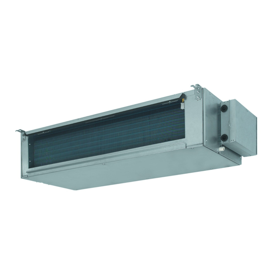
DUCTED AIR-CONDITIONING UNIT
Unit Model:
Indoor unit
FDM24PEV1K
FDM30PEV1K
FDM36PEV1K
FDM42PEV1K
FDM48PEV1K
FDYM24PEV1K
FDYM30PEV1K
FDYM36PEV1K
FDYM42PEV1K
FDYM48PEV1K
OPERATING AND INSTALLATION
INSTRUCTIONS MANUAL
Outdoor unit
R24PEV1K
R30PEV1K
R36PEY1K
R42PEY1K
R48PEY1K
RY24PEV1K
RY30PEV1K
RY36PEY1K
RY42PEY1K
RY48PEY1K
(7.0-14.0kW)
English
Advertisement
Table of Contents

Related Manuals for Daikin FDYM-PV1


Summary of Contents for Daikin FDYM-PV1
- Page 1 OPERATING AND INSTALLATION INSTRUCTIONS MANUAL DUCTED AIR-CONDITIONING UNIT English (7.0-14.0kW) Unit Model: Indoor unit Outdoor unit FDM24PEV1K R24PEV1K FDM30PEV1K R30PEV1K FDM36PEV1K R36PEY1K FDM42PEV1K R42PEY1K FDM48PEV1K R48PEY1K FDYM24PEV1K RY24PEV1K FDYM30PEV1K RY30PEV1K FDYM36PEV1K RY36PEY1K FDYM42PEV1K RY42PEY1K FDYM48PEV1K RY48PEY1K...
- Page 2 User Notice Ensure unifi ed power supply for each indoor unit. Never install wired controller in wet place or under sunlight directly. Shielding twisted pair line must be adopted as signal line or wiring (communication) of wired controller once the unit is installed in the place where there is electromagnetic interference.
-
Page 3: Table Of Contents
Contents I SAFETY PRECAUTIONS ........................2 II DISPLAYING PART ..........................6 2.1 LCD Display of Wired Controller ............................6 2.2 Instruction to LCD Display ..............................7 III BUTTONS ............................... 8 3.1 Silk Screen of Buttons ................................8 3.2 Instruction to Function of Buttons ............................8 IV INSTALLATION OF WIRED CONTROLLER .................. -
Page 4: Isafety Precautions
SAFETY PRECAUTIONS To gain full advantage of the air conditioner’s functions and to avoid malfunction due to mishandling, we recommend that you read this instruction manual carefully before use. This air conditioner is classifi ed under “appliances not accessible to the general public”. Please read these “SAFETY PRECAUTIONS”... - Page 5 • Be sure to earth the unit. Do not earth the unit to a utility pipe, lightning conductor or telephone earth lead. Imperfect earthing may result in electric shocks or fi re. A high surge current from lightning or other sources may cause damage to the air conditioner. •...
- Page 6 CAUTION • Do not use the air conditioner for purposes other than those for which it is intended. Do not use the air conditioner for cooling precision instruments, food, plants, animals or works of art as this may adversely affect the performance, quality and/or longevity of the object concerned. •...
- Page 7 • Watch your steps at the time of taking out or put back the air fi lter for cleaning or inspection. High-place work is required, to which utmost attention must be paid. If the scaffold is unstable, you may fall or topple down, thus causing injury. •...
-
Page 8: Displaying Part
DISPLAYING PART Fig. 2.1 Outline of wired controller 2.1 LCD Display of Wired Controller Fig. 2.2 LCD display English... -
Page 9: Instruction To Lcd Display
2.2 Instruction to LCD Display Description Instruction to Displaying Contents Swing* Swing function Air* Air exchange function Sleep Sleeping states Running mode Each kind of running mode of indoor unit (auto mode) Cooling Cooling mode Dry mode Heating Heating mode Defrost Defrosting state Gate-control... -
Page 10: Buttons
BUTTONS 3.1 Silk Screen of Buttons Fig. 3.1 Silk screen of buttons 3.2 Instruction to Function of Buttons Description Function of Button (1) Function selection and canceling; Enter/Cancel (2) Press it for 5s to enquiry the outdoor ambient temperature. (1) Running temperature setting of indoor unit, range :16 ∼ 30°C (2) Timer setting, range:0.5-24hr (3) Switchover between quiet/auto quiet Setting of high/middle/low/auto fan speed... -
Page 11: Installation Of Wired Controller
INSTALLATION OF WIRED CONTROLLER Fig. 4.1 Sketch for Installation of Wired Controller Socket’s base Soleplate of Front panel of Screw Description box installed in Screw M4X25 controller controller ST2.2X6.5 the wall Fig.4.1: Sketch for Installation of Wired Controller. Pay attention to the following items during the installation of wired controller: Cut off power supply before installation. -
Page 12: Instruction To Operation
INSTRUCTION TO OPERATION 5.1 On/Off Press On/Off button to turn on the unit. Repress this button to turn off the unit. Note: The state shown in Fig.5.1 indicates off-state of the unit after energization. The state shown in Fig.5.2 indicates on-state of the unit after energization. Fig. -
Page 13: Temperature Setting
5.3 Temperature Setting Press button for increase or decrease of setting temperature under on-state of the unit. If press either of them continuously, temperature will be increased or decreased by 1°C every 0.5s. In Cooling, Dry, Fan and Heating mode, temperature setting range is 16 ∼ 30°C. In Auto mode, the setting temperature is un-adjustable. -
Page 14: Swing Control Function
5.5 Swing Control Function* Under on-state of unit, press Function button till the unit enters swing control function and then press Enter/ Cancel button to turn on swing control function. During swing function, press Function button till the unit enters swing control function and then press Enter/ Cancel button to cancel swing control function. - Page 15 Timer off setting under on-state of the unit is shown as Fig.5.6 Turn on the unit, without Press “Timer” to set Press “ ” or “ ” button setting timer to adjust time Press “Timer” to confirm Press “ ” or “ ”...
-
Page 16: Air Exchange Setting
5.7 Air Exchange Setting* Turn-on air exchange function: Under on-state of the unit, press Function button into this function setting (Air mark blinks). AIR 1 displayed at the ambient temperature-displayed location (888) is defaulted (the last type of AIR will be displayed after adjustment). Press button to adjust air exchange type. -
Page 17: Sleep Setting
5.8 Sleep Setting Sleep on: Press Function button under on-state of the unit into Sleep function and then press Enter/Cancel button to turn on sleeping function. Sleep off: During sleep on state, press Function button into Sleep function and then press Enter/Cancel button to turn off this function. -
Page 18: Turbo Function Setting
5.9 Turbo Function Setting Turbo function: The unit at high fan speed can realize quick cooling or heating so that room temperature can quickly approach setting temperature. In cooling or heating mode, press Function button till the unit enters turbo function and then press Enter/Cancel button to turn on turbo function. - Page 19 After energy saving function is turned on, press Function button into energy saving function and press Enter/Cancel button to cancel this function. The energy saving setting is shown in the Fig.5.10. Turn on the unit, without Press “Function” button Press “ ”...
-
Page 20: E-Heater Setting
5.11 E-heater Setting* E-heater: In the heating mode, E-heater is allowed to be turned on for improvement of effi ciency. If heating mode is turned on by button operation, auxiliary electric heating function will be automati- cally turned on. Press Function button in heating mode into auxiliary electric heating function, E-HEATER blinking, and press Enter/Cancel button to turn on this function. -
Page 21: Blow Function Setting
5.12 Blow Function Setting Blow function: After the unit is turned off, water in evaporator of indoor unit will be automatically evaporated to avoid mildew. In cooling and dry mode, press Function button till the unit enters dry function, BLOW blinking, and then press Enter/Cancel button to turn on this function. -
Page 22: Quiet Function Setting
5.13 Quiet Function Setting Quiet function consists of 2 types: quiet and auto quiet. Press Function button till the unit enters quiet function setting state, QUIET or AUTO QUIET mark blinks. In this case, press button to switch between QUIET and AUTO QUIET and then press Enter/Cancel button to turn on this function. -
Page 23: Other Functions
5.14.1 Ambient Temperature Sensor Setting In fi eld setting mode, press Mode button to adjust the temperature displayed location displaying 00, and press button to adjust setting state at timer displayed location. There are 3 types for selection: Indoor ambient temperature is that at return air inlet (01 is displayed at timer displayed location) Indoor ambient temperature is that at the place of wired controller (02 is displayed at timer displayed location) Return air inlet temperature sensor shall be selected for cooling, dry and fan modes and wired controller... -
Page 24: Error Display
ERROR DISPLAY If there is malfunction during running of the system, LCD will display error code at temperature–displayed location. Once many malfunctions, error codes will be displayed circularly. If there are multiple circuit systems, the circuit number of failed system will be displayed before the colon (not for single circuit system). -
Page 25: Unit Function
UNIT FUNCTION Setting of Indoor Room Sensor and Checking of Outdoor Ambient Temperature 7.1 Setting of Double Indoor Room Sensors This series of ducted air-conditioning unit has two indoor room sensors. One is located at the air intake of the indoor unit and the other one is located inside the wired controller. -
Page 26: Fresh Air Control
7.3 Fresh Air Control* 11-levels control can be realized for the amount of fresh air taken in. The function not only facilitates the health of users, but also controls the electricity consumption loss because of taking in fresh air. This kind of control can be carried out through the wired controller. -
Page 27: Installation Instructions
VIII INSTALLATION INSTRUCTIONS Profi le Dimensions of Indoor Unit & Outdoor Unit 8.1 Dimensions of Indoor Unit 8.1.1 Dimensions of Indoor Unit Air Intake Air Supply Gas Pipe Liquid Pipe Drainage Pipe Electric Box Fig. For: FDM24PEV1K FDYM24PEV1K FDM30PEV1K FDYM30PEV1K FDM36PEV1K FDYM36PEV1K FDM42PEV1K... - Page 28 8.1.2 Dimension Requirement of the Installation Space of Indoor Unit Nut with Nut Spring Washer Washer Fig. For: FDM24PEV1K FDYM24PEV1K FDM30PEV1K FDYM30PEV1K FDM36PEV1K FDYM36PEV1K FDM42PEV1K FDYM42PEV1K FDM48PEV1K FDYM48PEV1K WARNING The height of installation for the indoor unit should be above 2.5m. English...
-
Page 29: Dimensions Of Outdoor Unit
8.2 Dimensions of Outdoor Unit 8.2.1 Dimensions of Outdoor Unit Fig. Unit : mm Model R42PEY1K R24PEV1K R30PEV1K R36PEY1K RY42PEY1K RY24PEV1K RY30PEV1K RY36PEY1K R48PEY1K Item RY48PEY1K 1018 1018 1107 1100 8.2.2 Dimension Requirement of the Installation Space of Outdoor Unit 0.5m 0.5m 0.5m... -
Page 30: Precautions On Installation Of Indoor Unit
Place of installation must ensure the machine will not be buried under snow or subject to the infl uence of rubbish or oil fog. The installation site must be at a place where the air exhaust outlet does not face strong wind. 8.4 Precautions on Installation of Indoor Unit 8.4.1 Selection of Installation Site Ensure the top hanging piece has strong strength to withstand the weight of the unit. -
Page 31: Level Check Of The Indoor Unit
PRECAUTIONS The preparation of all pipes (connecting pipes and drainage pipes) and cables (connecting lines of wired controller, indoor unit and outdoor unit) must be ready before the installation, so as to achieve smooth installation. Drill an opening on the ceiling. Maybe it is required to support the ceiling to ensure the evenness of it and avoid the vibration of it. -
Page 32: Installation Of Drainage Pipeline
CAUTION • The air supply pipe, the air intake pipe and the fresh air pipe must be covered with a layer of thermal insulation, so as to avoid thermal leakage and condensation. Firstly apply liquid nail on the pipes, then, attach the thermal insulation cotton with a layer of tinfoil. -
Page 33: Selection Of Connecting Pipe
8.9 Selection of Connecting Pipe Item Size of Fitting Max. Max. Height Amount of Additional Pipe (inch) Pipe Difference between Refrigerant to be Filled Length Indoor Unit and (For Extra Length of Liquid Outdoor Unit (m) Pipe) Model Pipe Pipe R24PEV1K+FDM24PEV1K RY24PEV1K+FDYM24PEV1K 60g/m... - Page 34 The following table describes the torques for tightening nuts of different pipe diameters. Pipe Diameter Tightening Torque 1/4” (inch) 15-30 (N·m) 3/8” (inch) 35-40 (N·m) 5/8” (inch) 60-65 (N·m) 1/2” (inch) 45-50 (N·m) 3/4” (inch) 70-75 (N·m) 7/8” (inch) 80-85 (N·m) The bending angle of the fi...
-
Page 35: Installation Of Protective Layer Of Connecting Pipe
8.11 Installation of Protective Layer of Connecting Pipe To avoid generation of condensate on the connecting pipe and leakage, the big pipe and the small pipe of the connecting pipe must be covered by thermal insulation materials, be bundled by adhesive tape, and be isolated from air. -
Page 36: Connection Of Signal Line Of Wired Controller
CAUTION During the installation of the bottom plate of the wired controller, pay attention to the direction of the bottom plate. The plate’s side with two notches must be at the lower position, otherwise, the panel of the wired con- troller cannot be correctly installed. -
Page 37: Electrical Installation
8.14 Electrical Installation CAUTION Before installing the electrical equipment, please pay attention to the following matters which have been specially pointed out by our designers: Check if the power supply used conforms to the rated power supply specifi ed on the nameplate. The capacity of the power supply must be large enough. -
Page 38: Power Cable Connection
8.15 Power Cable Connection: Air-conditioning unit with single-phase power supply Remove the front panel of the outdoor unit. Attach rubber ring to the cable-cross hole of the outdoor unit. Pass the cable though rubber ring. Connect the power supply cable to the “L, N” terminals and the grounding screw on the metal electric box. - Page 39 FDM36PEV1K+R36PEY1K FDYM36PEV1K+RY36PEY1K FDM42PEV1K+R42PEY1K FDYM42PEV1K+RY42PEY1K FDM48PEV1K+R48PEY1K FDYM48PEV1K+RY48PEY1K Outdoor Unit Indoor Unit L2 L3 N L N 1 breaker breaker L1 L2 L3 N PE L N PE Power: 380-415V 3N~50Hz Power: 220-240V~50Hz (1) Power cord 5×4mm² (H07RN-F) (2) Power cord 3×1.5mm² (H05VV-F) (3) Communication cords 2×0.75mm²...
- Page 40 Specifi cation of Power Supply Wire and Air Switch Outdoor Unit: Minimum Sectional Capability of Air Minimum Sectional Area of Power Power Supply Switch Area of Earth Wire Model Supply Wire (V, Ph, Hz) (mm²) (mm²) RY24PEV1K 220-240, 1, 50 R24PEV1K RY30PEV1K 220-240, 1, 50...
-
Page 41: Troubleshooting And Maintenance
8.17 Troubleshooting and Maintenance If your air-conditioning unit suffers from abnormal operation or failure, please fi rst check the following points before repair: Failure Possible Reasons The power supply is not connected. Electrical leakage of air-conditioning unit causes tripping of leakage switch. The unit cannot be started. - Page 42 8.18.2 Maintenance at the Beginning of Operating Season Check the air inlet and outlet of the indoor and outdoor units to confi rm there is no blockage. Check if the grounding wire is in good condition; Check if the line connection is in good condition; Check if there is any word displaying on the LCD of the wired controller after connecting the unit to power supply.
- Page 43 Appendix: Air conditioner nominal working condition and working range: Indoor side Outdoor side Test condition DB(°C) WB(°C) DB(°C) WB(°C) Nominal cooling Nominal heating – Rated cooling Low temp. cooling – Rated heating – Low temp. heating – –7 –8 Note: The design of this unit conforms to the requirements of ISO13253 standard.
-
Page 44: Specifications
SPECIFICATIONS English... - Page 45 EM09A058A (1002) 66129904511...