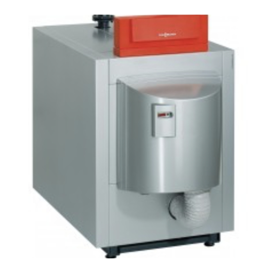
Viessmann Vitocrossal 200 Service Instructions For Contractors
Gas condensing boiler with matrix radiant burner 6 bar
Hide thumbs
Also See for Vitocrossal 200:
- Service instructions manual (96 pages) ,
- Service instructions for contractors (88 pages) ,
- Instructions manual (72 pages)
Table of Contents

Related Manuals for Viessmann Vitocrossal 200


Summary of Contents for Viessmann Vitocrossal 200
- Page 1 VIESMANN Service instructions for contractors Vitocrossal 200 Type CM2B, 87 to 311 kW Gas condensing boiler with MatriX radiant burner 6 bar For applicability, see the last page VITOCROSSAL 200 Please keep safe. 5677 612 GB 10/2016...
- Page 2 All current safety regulations as defined by DIN, EN, Replace faulty components only with original ■ DVGW, TRGI, TRF, VDE and all locally applicable Viessmann spare parts. standards. ÖNORM, EN, ÖVGW-TR Gas, ÖVGW-TRF and ÖVE SEV, SUVA, SVGW, SVTI, SWKI, VKF and...
- Page 3 Installing non-authorised components and making non-approved modifications or con- versions can compromise safety and may inva- lidate our warranty. For replacements, use only original spare parts supplied or approved by Viessmann.
- Page 4 Index Index 1. Information Symbols ....................Intended use ..................Product information ................2. Commissioning, inspec- Steps - commissioning, inspection and maintenance ......tion, maintenance 3. Vitotronic control unit Setting the codes at the control unit ............30 codes 4. Burner control unit Burner control unit VUC 310 ..............
- Page 5 Information Symbols The steps in connection with commissioning, inspec- Symbol Meaning tion and maintenance are found in the "Commission- Reference to other document containing ing, inspection and maintenance" section and identified further information as follows: Step in a diagram: Symbol Meaning The numbers correspond to the order in Steps required during commissioning...
- Page 6 Information Product information Vitocrossal 200 CM2B 87 to 311 kW with permissible operating pressure 6 bar (0.6 MPa). Gas condensing boiler for natural gas E and LL, with modulating MatriX radiant burner...
-
Page 7: Table Of Contents
Commissioning, inspection, maintenance Steps - commissioning, inspection and maintenance Commissioning steps Inspection steps Maintenance steps Page • 1. Checking the high limit safety cut-out setting..............• 2. Filling the heating system with water and venting............• 3. Filling the trap with water....................•... - Page 8 Commissioning, inspection, maintenance Steps - commissioning, inspection and… (cont.) Commissioning steps Inspection steps Maintenance steps Page • 39. Operating and service documents................... 29...
-
Page 9: Checking The High Limit Safety Cut-Out Setting
Commissioning, inspection, maintenance Checking the high limit safety cut-out setting The high limit safety cut-out must not be set higher Control unit installation and service instructions than 110 °C; if required, set it to a maximum of 110 °C. Filling the heating system with water and venting Record the volume filled, water hardness and pH value Note on page 56. - Page 10 Commissioning, inspection, maintenance Commissioning the system (cont.) 03. Check the gas supply pressure. 04. Open the gas line shut-off valves. 05. Switch ON the mains isolator (outside the installa- tion room). 06. Switch ON system ON/OFF switch at the con- trol unit.
-
Page 11: Checking The Gas Type
Commissioning, inspection, maintenance Checking the gas type 1. Check with your gas supply utility regarding the 2. In the delivered condition, the burner is set up for gas type and Wobbe index (Wo). natural gas E. If required, convert the burner to a ■... -
Page 12: Reducing The Operational Output (If Required)
Commissioning, inspection, maintenance Converting to natural gas LL (cont.) 04. Undo fitting 07. Remove restrictor with rubber cork gasket 08. Secure the gas train at flange : without restric- and without rubber cork gasket , but with O-ring . Replace factory-fitted screws M 5 ×... -
Page 13: Checking Static Pressure And Supply Pressure
Commissioning, inspection, maintenance Reducing the operational output (if required) (cont.) 7. Press S to switch to the operating display. Status Service 8. Press R A system restart is initiated. Fig. 6 Checking static pressure and supply pressure Static pressure 87 kW 115 to 311 kW Fig. - Page 14 Commissioning, inspection, maintenance Checking static pressure and supply pressure (cont.) Supply pressure 1. Start the burner. 3. Record the actual value in the report (on page 57). Note Commissioning: switch burner to max. heating out- 4. Close the gas shut-off valve. put.
-
Page 15: Checking The Rotary Damper Setting
Commissioning, inspection, maintenance Checking the rotary damper setting Fig. 9 1. Open the gas shut-off valve. 5. Check the position of the rotary damper during the start-up phase. Rotary damper windows must 2. Check the position of the rotary damper in burner be almost closed for approx. -
Page 16: Checking The Co2 Content
Commissioning, inspection, maintenance Checking the CO2 content Preparing the test 1. Open the gas shut-off valve. 2. Start the burner with the emissions test switch ena- bled. 3. Simultaneously hold down S for lon- ger than 2 s. Display then shows the following: ■... - Page 17 Commissioning, inspection, maintenance Checking the CO content (cont.) test at the lower heating output (87 kW) 1. Press until the service display has counted down to "0" (lower heating output). 2. Check the CO content at the flue pipe. Burner output in Permissible CO content in 8.5 (+0.2/-0.2)
- Page 18 Commissioning, inspection, maintenance Checking the CO content (cont.) test at the upper heating output (115 to 311 kW) 1. Press until the service display has counted up to "100" (= 100 %). 2. Check the CO content at the flue pipe. Burner output in Permissible CO content in...
-
Page 19: Checking The Flue Gas Temperature 13. Displaying The Ionisation Current
Commissioning, inspection, maintenance Checking the CO content (cont.) 3. If the CO content needs adjusting: ■ Undo cover ■ Turn adjusting screw in small increments (Torx 40). Continue turning until CO content rea- ches the specified range: – Turning clockwise content rises →... -
Page 20: Shutting Down The System
Commissioning, inspection, maintenance Shutting down the system 1. Switch OFF the mains isolator or the power supply, 2. Remove the burner hood. and safeguard against unauthorised reconnection. 3. Disconnect burner cables with plugs lÖ Danger from the burner control unit. Route the burner Mains voltage can be life threatening. -
Page 21: Checking All Connections And The Sensor Well On The Heating Water Side For Tightness
Commissioning, inspection, maintenance Checking all connections and the sensor well on the heating water side for tightness Fig. 18 Sensor well Note Also check the connections for the control equipment and the minimum pressure switch (low water indicator) for tightness. Removing the neutralising system, connecting the drain hose If a neutralising system is installed: 1. -
Page 22: Cleaning And Reconnecting The Condensate Drain System
3. Clean the neutralising system (if installed) in accordance with the manufacturer's instructions. Neutralising system operating instructions Note The neutralising agent can be obtained from Viessmann by quoting part no. 9521 702. 4. Undo and flush lower part of trap 5. Fill lower part of trap with water and reas- Fig. -
Page 23: Checking The Burner Gauze Assembly
Commissioning, inspection, maintenance Checking the burner gauze assembly Danger Escaping gas leads to a risk of explosion. Close the gas shut-off valve. Undo fitting on the gas supply pipe. 2. Undo the screws on the boiler door and open the door. -
Page 24: Closing The Boiler Door
Commissioning, inspection, maintenance Closing the boiler door Danger Leaks from the boiler door can result in poison- ing through escaping gas. Check the boiler door for flue gas tightness. To ensure that the boiler door closes tightly, adjust the clearance between boiler floor and hinge bolt to 16 mm ±... -
Page 25: Fitting The Burner
Commissioning, inspection, maintenance Cleaning the burner (cont.) 2. Remove Venturi mixing pipe 5. Clean the fan housing and impeller with com- from fan pressed air. 3. Remove Venturi mixing pipe with gas train and gas supply pipe 6. If required, vacuum the inside of burner gauze assembly Note For larger burners (246 to 311 kW), a rotary... -
Page 26: Checking The Gas Train Valves For Tightness
1 mbar (0.1 kPa) within 5 min. Otherwise there is a leak. In this case, return the gas train to your local Viessmann sales office for tests. 7. After testing, close both test connectors by tighten- ing the respective screws. -
Page 27: Checking The Gaskets On The Flue Gas Side
Commissioning, inspection, maintenance Checking the gaskets on the flue gas side Fig. 30 10 Nm Fig. 31 1. Check flue gas collector and boiler body tightness. -
Page 28: Performing Final Checks
Commissioning, inspection, maintenance Checking the gaskets on the flue gas side (cont.) 2. Check lip seal 3. If required, retighten the flue gas collector at ten- of the boiler flue connection for tightness. sioning toggles ; tighten screws diagonally with 10 Nm. -
Page 29: Checking The Installation Room Ventilation Air Apertures
Commissioning, inspection, maintenance Checking the installation room ventilation air apertures Check that the vent is unobstructed in the case of open flue operation. Instructing the system user The system installer should hand the operating instruc- This includes all components installed as accessories, tions to the system user and instruct the user in oper- e.g. - Page 30 Vitotronic control unit codes Setting the codes at the control unit Vitotronic service instructions In conjunction with the following control units: ■ Vitotronic 100, type GC1B ■ Vitotronic 200, type GW1B Vitotronic 300, type GW2B ■ Coding address Rated heating output of the MatriX radiant burner in kW Coding card 1041...
- Page 31 Burner control unit Burner control unit VUC 310 Display and programming unit A display and programming unit is integrated into the burner control unit. The display screen shows the rele- vant operating status, the service and parameter sta- tus, as well as any fault or error messages. The display comprises four elements of 7 segments Status Service...
- Page 32 Burner control unit Burner control unit VUC 310 (cont.) Status Service Status Service Flame stabilisation Maintenance program, no gas pressure or mains un- dervoltage Fig. 43 Fig. 40 Status Service Operation with flame Status Service Forced ventilation if no flame formation has been detected.
- Page 33 Burner control unit Burner control unit VUC 310 (cont.) Configurations: Menu Description point Changeover from the operating display of the burner control unit phase to other proc- ess information Configuration of control function operating parameters Menu point "5" is used to display the following process information: Sub-menu point Process information Units/scale...
- Page 34 Burner control unit Burner control unit VUC 310 (cont.) 3. S "6" is displayed under Status. 6. S to confirm. If reset successfully, "1" is shown under Service; if it failed, "0" is shown. until "0" is shown under Service. 7.
- Page 35 Burner control unit Burner control unit flow chart Fig. 45 Description of state: Phase Display Description Duration System start "A" System start 10 s Initialisation of fault meter 0.1 s Mains test, gas pressure Fan ramp-up, system start max. 20 s Forced ventilation, system start 20 s...
- Page 36 Burner control unit Burner control unit flow chart (cont.) Phase Display Description Duration Relay test "P" Fan ramp-up for test max. 20 s Safety relay test 0.9 s Disable relays BV1 and BV2. 0.9 s Relays test BV1 and BV2 0.9 s Ignition relay test 0.9 s...
- Page 37 Troubleshooting Fault display If the burner control unit switches to a fault state, the Fault code of the most recent fault (see table from fault display is automatically activated. The most page 37) recent fault is then displayed. The fault LED is also illu- minated in the case of a non-lockout fault, or flashes 1.
- Page 38 Troubleshooting Fault codes (cont.) Fault code dis- System characteristics Cause Measures played F b7 Burner control unit in a fault Coding card not inserted Insert coding card; check coding state; system cooling down; in the burner control unit; card, replace if required. burner control unit locked out.
- Page 39 Troubleshooting Fault codes (cont.) Fault code dis- System characteristics Cause Measures played F F4 Flame does not build during Incorrect gas type selec- Adjust gas type (see page 11). the safety time, no signal re- ported by the ionisation flame monitor.
- Page 40 Troubleshooting Fault codes (cont.) Fault code dis- System characteristics Cause Measures played F FA Fan runs without demand; Fan does not reach idle Fan subject to wind influence, burner control unit in a fault state, cable " A" faulty, check flue outlet and fan, replace a-Ö...
- Page 41 Parts lists Overview of assemblies The following details are required when ordering parts: ■ Serial no. (see type plate ■ Assembly (from this parts list) Position number of the individual part within the ■ assembly (from this parts list) Fig. 47 Type plate Thermal insulation assembly Boiler assembly...
- Page 42 Parts lists Boiler assembly 0001 0004 0003 0005 Fig. 48...
- Page 43 Parts lists Boiler assembly (cont.) Pos. Part 0001 CM2 flue gas cover with gasket 0003 Stench trap 0004 CM2 hinge bracket 0005 Base frame...
- Page 44 Parts lists Thermal insulation assembly 0008 0007 0015 0003 0015 0006 0005 0016 0011 0004 0009 0014 0001 0010 0013 0002 0012 0017 0018 0006 0014 Fig. 49...
- Page 45 0010 Thermal insulation jacket 0011 Thermal insulation mat, back 0012 Thermal insulation mat, front 0013 Right and left cover (strip) 0014 Vitocrossal 200 logo 0015 Edge protection 0016 Fixing rail, top 0017 Fixing rail, bottom 0018 Side panel, right front...
- Page 46 Parts lists Miscellaneous assembly 0001 0002 0003 0004 Fig. 50...
- Page 47 Parts lists Miscellaneous assembly (cont.) Pos. Part 0001 Touch-up spray paint, Vitosilver, 150 ml can 0002 Touch-up paint stick, Vitosilver 0003 Installation instructions 0004 Service instructions...
- Page 48 Component overview Overview of burner components Pressure-jet gas burner, type VMA III, 87 kW Fig. 51 Boiler door Burner control unit Ignition unit Display and programming unit Inlet adaptor for room sealed operation (optional) Gas supply pipe Gas pressure switch Gas shut-off valve Gas train Burner gauze assembly...
- Page 49 Component overview Overview of burner components (cont.) Pressure-jet gas burner, type VMA III, 115 to 311 kW Fig. 52 Boiler door Ionisation electrode Air pressure switch 1 Thermal insulation block Burner control unit Display and programming unit Ignition unit Gas train Suppressor choke box Gas supply pipe Inlet adaptor for room sealed operation (for 115,...
- Page 50 Function description Air pressure switch Fan pressure monitoring function (LDW1) If the static pressure check was unsuccessful after ■ approx. 5 minutes ■ If the air pressure is outside the permissible range during the pre-purge phase (tolerance time approx. 5 minutes) ■...
- Page 51 Function description Air pressure switch (cont.) Fan for burner 115 to 311 kW Fig. 55 Connector with screw ■ For 142 and 186 kW remove screw, attach power cable. Check for leaks. ■ For 115, 246 and 311 kW tighten the screw in the connector.
- Page 52 Connection diagrams Burner control unit connection diagram Fig. 56 Burner control unit VUC 310 Gas pressure switch 1 Fan motor with PWM control and feedback Air pressure switch 2 Air pressure switch 1 Display and programming unit...
- Page 53 Connection diagrams Burner control unit connection diagram (cont.) Fig. 57 Burner control unit VUC 310 F1 Backup fuse Flame monitor with ionisation current F2 Backup fuse F6 High limit safety cut-out Vitotronic control unit F7 Temperature controller Servomotor for rotary damper or 2/2-way solenoid valve H1 Hours run meter, modulation Ignition unit...
- Page 54 Water quality requirements Water quality requirements Note Prevention of damage due to scaling Observing the following requirements is necessary to safeguard your warranty rights. Prevent excessive scale build-up (calcium carbonate) The warranty excludes damage due to corrosion and on the heating surfaces. For heating systems with scaling.
- Page 55 Water quality requirements (cont.) Failure to observe the requirements of VDI Guideline Where chemicals are used as part of the corrosion 2035 can result in damaging limescale deposits. In protection, we recommend that the manufacturer of the such cases, the service life of the installed boilers will, chemicals issues a certificate of suitability of the addi- most often, already have been reduced.
- Page 56 Reports Reports Fill water report Fill water Top-up water Meter reading Total water volume Date — — — — — — — — — — — — — — — — — — — Max. fill volume: ......m Water quality report Total hardness pH value Water treatment...
- Page 57 Reports Reports (cont.) Settings and measurement values Commissioning Maintenance/service Static pressure mbar Supply pressure (flow pressure) for natural gas E mbar for natural gas LL mbar Tick gas type. Carbon dioxide content CO At the upper rated heat- actual % by vol. ■...
- Page 58 Specification Specification Specification Rated heating output TF/TR = 50/30 29 - 87 38 - 115 47 - 142 62 - 186 82 - 246 104 - 311 TF/TR = 80/60 27 - 80 35 - 105 43 - 130 56 - 170 75 - 225 95 - 285 Rated heat input...
- Page 59 The details for partial load refer to an output of 33 % of the rated heating output. If the partial load differs (subject to burner operating mode), calculate the flue gas mass flow rate accordingly. If using the Vitocrossal 200 with moisture-resistant chimneys, the draught must be no more than 0 Pa.
- Page 60 Specification Specification (cont.) Burner type VMA III-1 VMA III-2 VMA III-3 VMA III-4 VMA III-5 VMA III-6 Gas supply pressure mbar Gas connection 1¼ 1¼ MatriX radiant burner assignment Rated boiler heating output = 50/30 °C 29-87 38-115 47-142 47-186 82-246 104-311 = 80/60 °C...
- Page 61 Final decommissioning Final decommissioning and disposal Viessmann products can be recycled. Components and substances from the system are not part of ordi- nary household waste. For decommissioning the system, isolate the system from the power supply and allow components to cool down where appropriate.
- Page 62 Certificates Declaration of Conformity Vitocrossal 200, type CM2, 87 to 311 (80 to 285) kW, with Vitotronic boiler control unit and MatriX radiant burner We, Viessmann Werke GmbH & Co. KG, D-35107 Allendorf, declare as sole responsible body that the named...
- Page 63 Certificates Manufacturer’s certificate according to the 1st… (cont.) Allendorf, 19 July 2016 Viessmann Werke GmbH & Co. KG Authorised signatory Manfred Sommer...
- Page 64 Keyword index Keyword index Air pressure switch.............50 Ignition electrodes, checking........23 Instructing the system user........29 Intended use..............5 Boiler door, closing.............24 Internal system faults..........40 Boiler door, opening........... 20 Ionisation current display........... 19 Boiler water requirements.......... 54 Ionisation electrode, checking........23 Burner –...
- Page 68 Applicability Serial No.: 7554518 7554519 7554520 7554521 7554522 Viessmann Werke GmbH & Co. KG Viessmann Limited D-35107 Allendorf Hortonwood 30, Telford Telephone: +49 6452 70-0 Shropshire, TF1 7YP, GB Fax: +49 6452 70-2780 Telephone: +44 1952 675000 www.viessmann.com Fax: +44 1952 675040...