Table of Contents
Advertisement
Quick Links
Installer:
Leave this manual with the appliance.
Consumer: Retain this manual for future reference.
WARNING: If the information in these instructions
are not followed exactly, a fire or explosion may
result causing property damage, personal injury or
loss of life.
— Do not store or use gasoline or other flammable
vapors and liquids in the vicinity of this or any
other appliance.
— WHAT TO DO IF YOU SMELL GAS
•
Do not try to light any appliance.
•
Do not touch any electrical switch; do not use
any phone in your building.
•
Immediately call your gas supplier from a
neighbor's phone. Follow the gas supplier's
instructions.
•
If you cannot reach your gas supplier, call the
fire department.
— Installation and service must be performed by a
qualified installer, service agency or the gas sup-
plier.
INSTALLATION INSTRUCTIONS
OWNER'S MANUAL
AND
DIRECT VENT
WALL FURNACE
MODELS
DV210SGXLP-1
DV210SGXNAT-1
DV215SGXLP-1
DV215SGXNAT-1
This appliance may be installed in an after-market,
permanently located, manufactured home (USA only),
or mobile home, where not prohibited by state or local
codes.
This appliance is only for use with the type of gas
indicated on the rating plate. This appliance is not
convertible for use with other gases, unless a certified
kit is used.
WARNING: If not installed, operated, and maintained
in accordance with the manufacturer's instructions,
this product could expose you to substances in fuel
or from fuel combustion which can cause death or
serious illness.
Page 1
Advertisement
Table of Contents

Related Manuals for Empire Heating Systems DV210SGXLP-1


Summary of Contents for Empire Heating Systems DV210SGXLP-1
- Page 1 INSTALLATION INSTRUCTIONS OWNER'S MANUAL DIRECT VENT WALL FURNACE MODELS DV210SGXLP-1 DV210SGXNAT-1 DV215SGXLP-1 DV215SGXNAT-1 Installer: Leave this manual with the appliance. This appliance may be installed in an after-market, Consumer: Retain this manual for future reference. permanently located, manufactured home (USA only), or mobile home, where not prohibited by state or local codes.
-
Page 2: Table Of Contents
TABLE OF CONTENTS SECTION PAGE Important Safety Information ......................3 Safety Information for Users of LP Gas .................... 4 Requirements for Massachusetts ..................... 5 Introduction ............................6 Specifications ........................... 6 Gas Supply ............................7 Clearances ............................8 Installation Instructions ........................8-9 Lighting Instructions ........................ -
Page 3: Important Safety Information
IMPORTANT SAFETY INFORMATION THIS IS A HEATING APPLIANCE DO NOT OPERATE THIS APPLIANCE WITHOUT FRONT PANEL INSTALLED. • Due to high temperatures the appliance should be • More frequent cleaning may be required due to ex- located out of traffic and away from furniture and cessive lint from carpeting, bedding materials, etc. -
Page 4: Safety Information For Users Of Lp Gas
SAFETY INFORMATION FOR USERS OF LP-GAS Propane (LP-Gas) is a flammable gas which can cause fires SOME POINTS TO REMEMBER and explosions. In its natural state, propane is odorless and • Learn to recognize the odor of LP-gas. Your local LP-Gas colorless. -
Page 5: Requirements For Massachusetts
REQUIREMENTS FOR MASSACHUSETTS For all side wall horizontally vented gas fueled equipment installed SIGNAGE. A metal or plastic identification plate shall be per- in every dwelling, building or structure used in whole or in part for manently mounted to the exterior of the building at a minimum residential purposes, including those owned or operated by the height of eight (8) feet above grade directly in line with the Commonwealth and where the side wall exhaust vent termination exhaust vent terminal for the horizontally vented gas fueled is less than seven (7) feet above finished grade in the area of the heating appliance or equipment. The sign shall read, in print size no less than one-half (1/2) inch in size, “GAS VENT DI-... -
Page 6: Introduction
INTRODUCTION Introduction Qualified Installing Agency Always consult your local Building Department regarding regulations, Installation and replacement of gas piping, gas utilization equipment codes or ordinances which apply to the installation of a direct vent or accessories and repair and servicing of equipment shall be wall furnace. performed only by a qualified agency. The term "qualified agency" means any individual, firm, corporation or company which either in Instructions to Installer person or through a representative is engaged in and is responsible for 1. Installer must leave instruction manual with owner after (a) the installation or replacement of gas piping or (b) the connection, installation. installation, repair or servicing of equipment, who is experienced in 2. Installer must have owner fill out and mail warranty card supplied such work, familiar with all precautions required and has complied with furnace. -
Page 7: Gas Supply
GAS SUPPLY Locating Gas Supply checked for leaks by the installer. This should be done with a soap The gas line can enter the unit either through the floor or outside solution watching for bubbles on all exposed connections, and if wall. The gas line opening should be made at this time. Location unexposed, a pressure test should be made. of the opening will be determined by the position of floor joists and Never use an exposed flame to check for leaks. Appliance must be the valve and union used for servicing. disconnected from piping at inlet of control valve and pipe capped or plugged for pressure test. Never pressure test with appliance Recommended Gas Pipe Diameter connected; control valve will sustain damage! Schedule 40 Pipe Tubing, Type L A gas valve and ground joint union should be installed in the gas Inside Diameter Outside Diameter Pipe Length line upstream of the gas control to aid in servicing. It is required by the National Fuel Gas Code that a drip line be installed near the gas... -
Page 8: Clearances
CLEARANCES 1. In selecting a location for installation, it is necessary to provide The vent terminal of a direct vent appliance, with an input of 10,000 adequate accessibility clearances for servicing and proper Btu per hour (3 kW) or less shall be located at least 6" (150mm) installation. from any air opening into a building, and such an appliance with an 2. Although certified for 0 clearance to the floor , the unit is held in input over 10,000 Btu per hour (3 kW) but not over 50,000 Btu per place by a wall bracket. Enough clearance [2" (51mm) suggested] hour (14.7 kW) shall be installed with a 9" (229mm) vent terminal to allow changing or adding floor covering is recommended. clearance and the bottom of the vent terminal and the air intake Other clearances to combustible construction: shall be located at least 12" (305mm) above grade. Sides 1" (25mm) and 12" (305mm) from the top. WARNING: The nearest point of the vent cap should be a minimum 3. Note the position of the vent relative to the center of the unit. horizontal distant of six (6) feet (1.8m) from any pressure regulator. The DV-210 has the vent in the center. The DV-215 vent is 2" In case of regulator malfunction, the six feet (1.8m) distance will (51mm) off center to the right. reduce the chance of gas entering the vent cap. - Page 9 INSTALLATION INSTRUCTIONS (continued) Cutting Vent Tubes 5. Reassembly and resealing vent-air intake system is completed. This is the most important part of the installation. With the furnace Installing a Vent Near a Window Ledge, Other Type of Projection installed on wall the 5" (127mm) diameter air inlet tube and 3" or on Siding (vinyl, aluminum, etc.) (76mm) diameter flue outlet tube are to be marked and cut using Direct vent furnaces are designed to be installed on a uniform...
-
Page 10: Lighting Instructions
LIGHTING INSTRUCTIONS FOR YOUR SAFETY READ BEFORE LIGHTING WARNING: If you do not follow these instructions exactly, a fire or explo- sion may result causing property damage, personal injury or loss of life. A. This appliance has a pilot which must be lighted by C. -
Page 11: Maintenance
MAINTENANCE Piezo Pilot Ignitor Instructions These heaters are specially designed for use on self generating systems. They should never be used on line or low voltage A.C. Depressing the piezo ignitor button completely causes a spark to circuits. occur at the pilot. This is a substitute for a match which requires opening the pilot hole cover. Installing the ON/OFF Device To light the pilot, it is important that the electrode be 1/8" (3 mm) To install an ON/OFF device (such as a wall switch, remote, toggle from the thermopile. The spark must occur at the point the burner switch,or thermostat), remove the wire nut from the two wires from flame hits the thermopile. The end of the electrode will be red hot the valve. Run additional wire from the valve wires to the ON/OFF with the pilot on. - Page 12 PILOT FLAME CHARACTERISTICS The pilot flame is blue and goes toward the main burner and thermopile horizontally. A slight yellow tip on the flame is normal. The pilot flame must surround and extend approximately 1/4" (6mm) beyond the thermopile, and must extend beyond the first row toward the second row of main burner ports. Figure 7 MAIN BURNER FLAME CHARACTERISTICS On the main burner, the burning gas forms a primary flame and a secondary flame. The primary flame is blue and about 3/16" (5mm) high. The secondary flame is very pale blue, 3 inches (76mm) to 5 inches (127mm) high. Dust in the combustion air will produce an orange flame. Do not mistake it for an improper yellow flame. Figure 8 Page 12...
-
Page 13: Pilot Flame Characteristics
TROUBLESHOOTING Lit match goes out as it enters lighter port. Pilot and main burner go out during normal operation. Certain wind conditions will blow out match. Ignite Check millivolts. match, and as it flares, thrust match through opening. Check for proper size of pilot flame. Open nearby door or window and relight pilot. Check for defective or weak thermopile. Check input, reduce as needed. Pilot flames but goes out when knob is released. -
Page 14: Parts List
PARTS LIST Index Part Index Part Description Description TH100 WALL MOUNTING PLATE M151 GASKET - PILOT BURNER TH104 GASKET - FOR WALL MOUNTING PLATE TH133 CHAMBER DOOR WITH GASKET - DV210 TH015 AIR DROP ASSEMBLY - DV210 TH134 CHAMBER DOOR WITH GASKET - DV215 TH018 AIR DROP ASSEMBLY - DV215 TH365 VALVE BRACKET 11757 OUTER CASING - DV210 PILOT TUBING - 1/4" (6.4mm) WITH FER- TH336 RELLS (Nat.) 11758... -
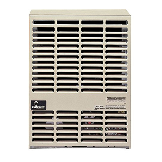
Page 15: Parts View
PARTS VIEW Page 15... -
Page 16: Optional Blower Installation Instructions
OPTIONAL BLOWER INSTALLATION INSTRUCTIONS DVB-1 For Direct Vent Wall Furnaces DV210 and DV215 Wiring INSTALLING OPTIONAL BLOWER DVB-1. The blower must be positioned as shown in Figure 1. Relocate gas line, if necessary, The appliance, when installed, must be electrically grounded in using elbow fitting at the gas valve, and move Piezo Spark Genera- accordance with local codes or, in the absence of local codes, with tor to the next screw. A slot on the bottom of the blower package the National Electrical Code, ANSI/NFPA 70 or Canadian Electrical engages a tab on the bottom of the inner casing and is secured by Code, CSA C22.1, if an external electrical source is utilized. This one screw in front. - Page 17 OPTIONAL BLOWER INSTALLATION INSTRUCTIONS DVB-1 For Direct Vent Wall Furnaces DV210 and DV215 Oiling the Motor Oiling holes are provided on each end of the motor for oiling. The blower should have five drops of #20 motor oil every 6 months. Do not use machine oil. Cleaning the Blower Wheel In some areas, such as near bedrooms and on floors with a hard surface, the blower wheel will be filled with lint very quickly. A visual check of the blower wheel should be made after 30 days use. The blower will run faster with a dirty wheel, but move less air. Remove the entire blower and clean each blade of the wheel with a tooth brush as often as necessary.
-
Page 18: Master Parts Distributor List
MASTER PARTS DISTRIBUTOR LIST To Order Parts Under Warranty, please contact your local Empire dealer. To provide warranty service, your dealer will need your name and address, purchase date and serial number, and the nature of the problem with the unit. To Order Parts After the Warranty Period, please contact your dealer or one of the Master Parts Distributors listed below. This list changes from time to time. Please note: Master Parts Distributors are independent businesses that stock the most commonly ordered Original Equip- ment repair parts for Heaters, Grills, and Fireplaces manufactured by Empire Comfort Systems Inc. HOW TO ORDER REPAIR PARTS Parts Not Under Warranty Parts can be ordered through your Service Person, Dealer, or a Master Parts Distributor. See this page for the Master Parts Distribu- tors list. For best results, the service person or dealer should order parts through the distributor. Parts can be shipped directly to the service person/dealer. -
Page 19: Warranty
WARRANTY Empire Comfort Systems Inc. warranties this space heating product to be free from defects at the time of purchase and for the periods specified below. Space heating products must be installed by a qualified technician and must be maintained and operated safely, in accordance with the instructions in the owner’s manual. This warranty applies to the original purchaser only and is not transferable. All warranty repairs must be accomplished by a qualified gas appliance technician.