Empire Heating Systems FAW-40-1IP Installation Instructions And Owner's Manual
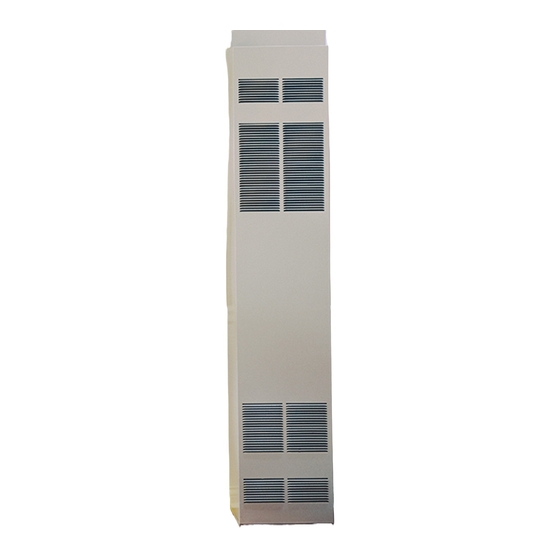
Fan type vented wall furnace
Hide thumbs
Also See for FAW-40-1IP:
- Installation instructions and owner's manual (41 pages) ,
- Installation instruction and owenrs manual (18 pages)
Table of Contents
Advertisement
Available languages
Available languages
Installer: Please leave these instructions with
the consumer.
Consumer: Please retain these instructions for
future use.
WARNING: If not installed, operated and
maintained in accordance with the manu-
facturer's instructions, this product could
expose you to substances in fuel or from
fuel combustion which can cause death or
serious illness.
12427-4-0306
INSTALLATION INSTRUCTIONS
OWNER'S MANUAL
AND
FAN TYPE
VENTED
WALL FURNACE
MODEL
FAW-40-1SPP
FAW-40-1IP
EFFECTIVE DATE
MARCH 2006
WARNING: If the information in this
manual is not followed exactly, a fire or
explosion may result causing property
damage, personal injury or loss of life.
— Do not store or use gasoline or other flam-
mable vapors and liquids in the vicinity
of this or any other appliance.
— WHAT TO DO IF YOU SMELL GAS
•
Do not try to light any appliance.
•
Do not touch any electrical switch; do
not use any phone in your building.
•
Immediately call your gas supplier
from a neighbor's phone. Follow the
gas supplier's instructions.
•
If you cannot reach your gas supplier,
call the fire department.
— Installation and service must be per-
formed by a qualified installer, service
agency or the gas supplier.
Page 1
Advertisement
Table of Contents

Related Manuals for Empire Heating Systems FAW-40-1IP


Summary of Contents for Empire Heating Systems FAW-40-1IP
-
Page 1: Installation Instructions
FAN TYPE VENTED WALL FURNACE MODEL FAW-40-1SPP FAW-40-1IP EFFECTIVE DATE MARCH 2006 • Do not try to light any appliance. • Do not touch any electrical switch; do not use any phone in your building. - Page 2 2. Installer must have owner fill out and mail warranty card supplied with furnace. 3. Installer should show owner how to start and operate furnace and thermostat. Warning: Any change to this furnace or its control can be dangerous. This...
- Page 3 SAFETY INFORMATION FOR USERS OF LP-GAS Propane (LP-Gas) is a flammable gas which can cause fires and explosions. In its natural state, propane is odorless and colorless. You may not know all the following safety precau- tions which can protect both you and your family from an accident.
- Page 4 For example, a space including a water heater rated at 40,000 Btuh input and a furnace rated at 40,000 Btuh requires a volume of 4,000 cubic feet (50 x (40 + 40) = 4,000) to be considered as unconfined.
- Page 5 Maintain 3/4" minimum spacing above heater. 3. The wall in which the furnace is recessed has (0) zero (0mm) clearance to the furnace sides. 4. When using side discharge registers, SOR-1 or SOK-1, the furnace cannot be recessed into the wall.
- Page 6 Page 6 and attach side wall plate to furnace side of wall with (2) #10 x 1 1/2" (38mm) provided screws. 5. Attach outer boot to the cabinet side with (4) #8 x 1/4" (6mm) provided screws.
- Page 7 11. Installation of ROK-1 is completed. Locating Furnace On Wall The furnace is to be located on a wall. The furnace is 14 1/8" (35.9cm) in width and can be recessed into the wall with typical stud spacing. A template is provided in furnace carton for locating gas line connection.
- Page 8 flame. The burner does not have a primary air adjustment. The flame will be correct if the factory-set pressure and orifice opening are used. After the furnace has been operating, the burner ports may be blocked by foreign matter carried in by combustion air. Therefore, cleaning of the burner may be needed for proper flame.
- Page 9 Thermostat Installation The thermostat should be installed in the same room as the furnace 4' (1.2m) to 5' (1.5m) above the floor and away from another heat source (cooking stove, hot water heater, etc.) including walls and doorways with a heat source in an adjoining room.
- Page 10 Spark Igniter Does Not Light Pilot: With air in the gas line, such as when the furnace is first installed or was off all summer, the pilot flame may be too lean to ignite on the first few trials. Turn the control valve knob to pilot position and depress the red reset button.
-
Page 11: Lighting Instructions
FOR YOUR SAFETY READ BEFORE LIGHTING WARNING: If you do not follow these instructions exactly, a fire or explosion may result causing property damage, personal injury or loss of life. A. This appliance has a pilot which must be lighted by hand. -
Page 12: Operating Instructions
FOR YOUR SAFETY READ BEFORE OPERATING WARNING: If you do not follow these instructions exactly, a fire or explosion may result causing property damage, personal injury or loss of life. A. This appliance is equipped with an ignition device which automatically lights the pilot. -
Page 13: Sequence Of Operation
SEQUENCE OF OPERATION START System Check Trial for Ignition Main Burner Operation (1) Ignitor will turn OFF about 30 seconds into the trial for ignition if the pilot flame has not lit. It will turn back ON for the final 30 seconds of the 90 second trial for ignition. - Page 14 START IP SYSTEM TROUBLESHOOTING SEQUENCE Turn OFF Gas Supply Disconnect System Control Harness Set Thermostat to Call for Heat Check for Proper Voltage at Control Harness (See Inset A - Voltage Should be 24V Between Thermostat and 24V Common, and 24V Between 24V Common and 24V Hot.) Plug Harness into SmartValve...
- Page 15 Then determine the Part Number (not the Index Number) and the Description of each part from the following appropriate illustration and list. Be sure to give all this information. Furnace Model Number Furnace Serial Number Type of Gas (Propane or Natural) Do not order bolts, screws, washers or nuts.
- Page 16 Page 16 12427-4-0306...
-
Page 17: Service Notes
Service Notes Page 17 12427-4-0306... - Page 18 Empire Comfort Systems, Inc. Nine Eighteen Freeburg Ave. Belleville, Illinois 62220-2623 Page 18 PH: 1-618-233-7420 PH: 1-800-851-3153 FAX: 1-618-233-7097 FAX: 1-800-443-8648 E-MAIL: info@empirecomfort.com WEB SITE: www.empirecomfort.com 12427-4-0306...
- Page 19 Si vous ne pouvez pas contacter votre fournis- seur de gaz, appeler le poste de pompiers. — L’installation et le service doivent être exécutés par un installateur qualifié, une agence d’entretien ou un fournisseur de gaz. ÉVACUATION MODÈLE FAW-40-1SPP FAW-40-1IP Page 1...
- Page 20 Introduction Toujours consulter le département de construction de votre région en ce qui regarde les règlements, les codes ou les ordonnances qui s’appliquent à l’installation d’un radiateur mural avec évacuation. Instructions pour l'Installateur 1. Après l’installation, l’installateur doit laisser le manuel d’instructions au propriétaire.
- Page 21 INFORMATION DE SÉCURITÉ POUR LES UTILISATEURS DE PROPANE Le propane est un gaz inflammable qui peut causer des feux et des explosions. Dans son état naturel, le propane est inodore et sans couleur. Peut-être que vous ne connaissez pas toutes les précautions décrites ci-dessous? Elles peuvent vous protéger ainsi que votre famille contre un accident.
- Page 22 Air de Ventilation et de Combustion ATTENTION: Danger pour des dommages à la propriété, des blessures ou la mort, ce radiateur et d’autre sorte d’appareil au gaz doivent avoir assez d’air frais pour permettre une bonne combustion et une bonne ventilation des gaz d’échappement. La plupart des maisons exigera que l’air extérieur soit accessible.
- Page 23 Si l’air de combustion est pris à l’extérieur par des conduits horizontaux, les ouvertures et les conduits doivent avoir un espace libre minimum de 1" (6.5cm ) par 2,000 Btuh d’entrée totale pour l’appareil. Agence d’Installation Qualifiée L’installation et le remplacement des tuyaux à gaz, des équipements ou accessoires, la réparation et l’entretien de l’équipement doivent être faits seulement par une agence qualifiée.
- Page 24 4. Les évents à gaz de type B-1 ou (B-W) pour plus d’un étage exige une plaque de base, une paire d’entretoises pour la plaque du plafond, au plafond du premier étage et une paire d’entretoises pour l’arrêt de feu à chaque niveau de plafond successif. L’espace entre les montants autour des évents à...
- Page 25 arrière pour former un carré. Percer un trou pilote à l’intérieur du carré que vous avez tracé sur la paroi extérieure arrière. Enlever la feuille de métal à l’intérieur du carré que vous avez tracé, avec des ciseaux à métal ou un outil comparable. 3.
- Page 26 TUYAU D’ALIMENTATION EN GAZ VALVE DE FERMETURE MANUELLE ARRIVÉE D’ALIMENTATION DE GAZ 3” (76mm) MINIMUM BONDE NPT DE 1/8” (3mm) POUR VÉRIFIER LE JAUGEAGE DES (3mm) CONNEXIONS Figure 8 Méthode pour installer un collecteur de sédiment avec un adapteur en T L’emploi des connexions de gaz suivantes est recommandé.
- Page 27 Aspect Convenable de la Flamme du Brûleur Principal La flamme convenable aura une petite flamme bleue intérieure avec une flamme extérieure bleue pâle beaucoup plus grande. Il n’y a pas d’ajustement d’air primaire pour le brûleur. La flamme se corrigera si la pression pré-ajustée à...
- Page 28 Figure 13 CONNECTEUR DU TUYAU D’ÉVACUATION INTERRUPTEUR DE FIN DE COURSE POUR L’ÉVENT VENTILATEUR INTERRUPTEUR DE FIN DE COURSE FAN SWITCH ALLUMEUR PIEZO Page 10 SUGGESTIONS POUR LE SERVICE ET L’ENTRETIEN. Général : Tous les radiateurs ont reçu un test d’allumage pour vérifier le bon fonctionnement.
- Page 29 Veilleuse modèle IP Ce radiateur utilise un système “Smart Valve” Honeywell pour l’allumage intermittent de la veilleuse. Lors d’un appel de chaleur par le thermostat, cette commande fera fonc- tionner la mini surface chaude d’allumage laquelle allumera la veilleuse qui elle à son tour allumera le brûleur principal. La soupape de gaz qui est utilisée dans ce système s’ouvre par étape ce qui veux dire quelle ouvrira à...
-
Page 30: Instructions D'allumage
POUR VOTRE SÉCURITÉ LIRE AVANT D’ALLUMER AVERTISSEMENT: Si vous ne suivez pas exactement ces instructions, un feu ou une explosion peut se produire causant des dommages à la propriété, des blessures corporelles ou la mort. A. Cet appareil a une veilleuse qui doit être allumée manuel- lement. - Page 31 POUR VOTRE SÉCURITÉ LIRE AVANT D’ALLUMER AVERTISSEMENT: Si vous ne suivez pas exactement ces instructions, un feu ou une explosion peut se produire causant des dommages à la propriété, des blessures corporelles ou la mort. A. Cet appareil est muni d'un dispositif d'allumage lequel allume automatiquement la veilleuse.
- Page 32 Page 14 12427(F)-3-0903...
- Page 33 Page 15 12427(F)-3-0903...
- Page 34 PLEASE NOTE: When ordering parts, it is very important that part number and description of part coincide. Index Part Number Description WFA-115 Joint d’étanchéité DV-1247 Plaque du dessus (USA) 15668 Plaque du dessus (CANADA) R-3165 Agrafe pour la porte (exige 2) DV-1204 Paroi de côté...
- Page 35 VEILLEUSE ET SUP- PORT POUR LES MODÉ- LES SPP Empire Comfort Systems, Inc. Nine Eighteen Freeburg Ave. Belleville, Illinois 62222-0529 Page 17 12427(F)-3-0903...
- Page 36 Empire Comfort Systems, Inc. Nine Eighteen Freeburg Ave. Belleville, Illinois 62220-2623 Page 18 PH: 1-618-233-7420 PH: 1-800-851-3153 FAX: 1-618-233-7097 FAX: 1-800-443-8648 E-MAIL: info@empirecomfort.com WEB SITE: www.empirecomfort.com 12427(F)-3-0903...