Table of Contents
Advertisement
Quick Links
Instruction Manual
Form 1432
April 1998
. . . . . . . . . . . . . . . . . . . . . . . . . . . . . .
. . . . . . . . . . . . . . . . . . . . . . . . . . . . .
. . . . . . . . . . . . . . . . . . . . . . . . . . . . . . . . . .
. . . . . . . . . . . . . . . . . . . . . . . . . . . . . . .
. . . . . . . . . . . . . . . . . . . . . . . . . . . . . . . .
. . . . . . . . . . . . . . . . . . . . . . . . . . . .
. . . . . . . . . . . . . . . . . . . . . . . . . .
. . . . . . . . . . . . . . . . . . . . . . . . . . . . . .
. . . . . . . . . . . . . . . . . . . . . . . . . . . . . . . . . . . . . .
. . . . . . . . . . . . . . . . . . . . . . . . . . . . . . . . . . . . . .
. . . . . . . . . . . . . . . . . . . . . . . . . . . . . .
. . . . . . . . . . . . . . . . . . . . . . . . . . . . . . .
. . . . . . . . . . . . . . . . . . . . . . . . . . . . . . . . . .
. . . . . . . . . . . . . . . . . . . . . . . . . . . . .
. . . . . . . . . . . . . . . . . . . . . . . . . . . . . . . .
. . . . . . . . . . . . . . . . . . . . . . . . . . . . .
. . . . . . . . . . . . . . . . . . . . . . . . . . . . . . . .
. . . . . . . . . . . . . . . . . . . . . . . . . . .
. . . . . . . . . . . . . . . . . . . . . . . . . . . . . . . .
. . . . . . . . . . . . . . . . . . . . . . . . . . . . . . . . .
Scope of Manual
This instruction manual provides information on instal-
lation, adjustment, maintenance, and parts ordering for
1
1
2
2
. . . . . . . . . . . . . . . . .
3
3
3
4
4
4
4
. . . . . . . . . . . . . . . . . . . . . .
4
. . . . . . . . . . . . . . . . . . . . .
5
5
. . . . . . . . . . . . . . . . .
6
6
7
. . . . . . . . . . . . . . . .
9
. . .
9
. . . .
12
. . . . . . . . . . . .
14
14
14
. . . . . . . . . . . . . . . . . .
15
. . . . . . . . . . .
15
16
16
16
16
17
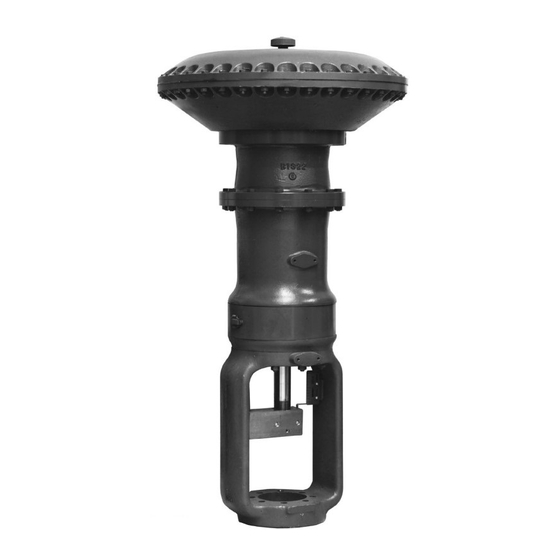
Type 667 Sizes 80 & 100
W1950 / IL
Figure 1. Size 80 Type 667 Actuator
the Type 667 actuator in sizes 80 and 100 (figure 1).
Refer to separate instruction manuals for information
about other equipment and accessories used with
these actuators.
Only personnel qualified through training or experience
should install, operate, and maintain a Type 667 ac-
tuator. If you have any questions about these instruc-
tions, contact your Fisher Controls sales office or
sales representative before proceeding.
Advertisement
Table of Contents

Related Manuals for Emerson Fisher Type 667 size 80


Summary of Contents for Emerson Fisher Type 667 size 80
-
Page 1: Table Of Contents
Instruction Manual Form 1432 Type 667 Sizes 80 & 100 April 1998 Introduction ......Scope of Manual . -
Page 2: Description
Type 667 Sizes 80 & 100 Table 1. Specifications ACTUATOR SIZE SPECIFICATION SPECIFICATION inch Nominal Effective Diaphragm Area Nominal Effective Diaphragm Area 1761 2902 inch Yoke Boss Diameters Yoke Boss Diameters inch 1 or 1-1/4 1-1/4 Acceptable Valve Stem Diameters Acceptable Valve Stem Diameters 25.4 or 31.8 31.8... -
Page 3: Maximum Pressure Limitations
Type 667 Sizes 80 & 100 WARNING When an actuator and valve body are shipped togeth- er, the actuator is normally mounted on the valve. Fol- low the valve body instructions when installing the To avoid personal injury or parts dam- control valve in the pipeline. -
Page 4: Loading Connection
Type 667 Sizes 80 & 100 When adjusting travel of a direct-acting valve, put a WARNING slight pressure on the actuator diaphragm. This moves the valve plug off the seat, reducing the chance of damaging the valve plug or seat during adjustments. To avoid personal injury due to the sud- den, uncontrolled movement of parts, 1. -
Page 5: Size 100 Actuator Spring
Type 667 Sizes 80 & 100 Size 100 Actuator Spring CAUTION SPRING SEAT The actuator must be in the vertical position when adjusting the spring to avoid damage to thrust bearing (key 86, figure 7) and to properly position the spacers required for adjustment. -
Page 6: Size 80 Actuator Maintenance
Type 667 Sizes 80 & 100 stem connector (key 31) when spring WARNING force is applied. 5. If necessary, the entire actuator assembly may be Avoid personal injury from sudden re- removed from the valve body by unscrewing the cap lease of process pressure. -
Page 7: Assembly
Type 667 Sizes 80 & 100 b. Replace packing and O-rings (keys 118, 119, 8. Coat gasket (key 70) with lubricant (key 237) or 96, 107, and 120). equivalent. Position the lower diaphragm casing (key 64) on the spring case adaptor, and secure with cap screws (key 30). - Page 8 Type 667 Sizes 80 & 100 VENT ASSEMBLY (KEY 17) CAP SCREW (KEY 12) UPPER DIAPHRAGM PLATE (KEY 4) SPACER (KEY 2) CAP SCREW (KEY 13) UPPER DIAPHRAGM CASE (KEY 1) HEX NUT (KEY 14) DIAPHRAGM (KEY 3) LOWER DIAPHRAGM LOWER DIAPHRAGM CASE (KEY 64) PLATE (KEY 71)
-
Page 9: Size 100 Actuator Maintenance
Type 667 Sizes 80 & 100 Size 100 Actuator Maintenance outline the procedure required to de- crease high spring compression. For size 100 actuators, refer to figure 5 for part names and locations. Key number locations for Size 100 ac- Loosen jam nut (key 26), and rotate adjusting nut (key tuators are shown in figure 7. - Page 10 Type 667 Sizes 80 & 100 DIAPHRAGM CASING CAP SCREW (KEY 12) COVER (KEY 15) UPPER DIAPHRAGM HEX NUT (KEY 24) PLATE (KEY 4) HEX NUT (KEY 241) UPPER DIAPHRAGM CASING (KEY 1) WASHER (KEY 37) DIAPHRAGM (KEY 3) CAP SCREW (KEY 13) O-RING (KEY 240) BACK UP PLATE (KEY 6) SEAL BUSHING...
- Page 11 Type 667 Sizes 80 & 100 6. Install diaphragm backup plate, diaphragm retainer, WARNING diaphragm, upper diaphragm plate, and washer (keys 6, 5, 3, 4, and 37) on the actuator stem (key 144). To avoid personal injury and property Note damage from the sudden release of spring load, be sure that all spring load Install diaphragm with the fabric side...
-
Page 12: For Actuators With The Top-Loaded Option
Type 667 Sizes 80 & 100 10. Insert the cap screws (key 13) into the upper dia- 4. Remove the diaphragm plate (key 4) with O-ring phragm casing, and tighten the hex nuts (key 14) in (key 240, diaphragm (key 3), diaphragm retainer (key the following manner. - Page 13 Type 667 Sizes 80 & 100 Note manual torque wrench for size 80 and 100 actuators. When installing lower diaphragm cas- ing, install O-rings (key 70) into grooves Note found in the lower diaphragm casing before placing the casing on the yoke Do not use lubricant on these bolts and assembly.
-
Page 14: Size 80 Side-Mounted Handwheel
Type 667 Sizes 80 & 100 17. Position the upper diaphragm casing (key 1) on 26. Mount the actuator on the valve, and secure with the diaphragm (key 3) and align the holes. the actuator-to-bonnet bolting. Refer to the Installation section to connect actuator stem to valve plug stem. -
Page 15: Size 80 Hydraulic Snubber
Type 667 Sizes 80 & 100 screw slot in the worm retainer with the set screw hole Note in the gear case, insert the set screw, and tighten. Overtightening the set screws will make 3. Coat the worm shaft (key 51) threads with Lubri- handwheel operation difficult. -
Page 16: Disassembly
Type 667 Sizes 80 & 100 Instructions are given below for complete disassembly shaft into the gear case so that the end of the shaft fits and assembly. Disassemble only as far as necessary snugly in the back worm retainer. to accomplish the required maintenance;... - Page 17 Type 667 Sizes 80 & 100 Description Part Number Cap Screw, steel Size 80 3/4 to 1-inch travel (19 to 25 mm) 1R412031192 1-1/8 inch travel (29 mm) 1R411931192 Actuator 1-1/2 inch travel (38 mm) 1R411831192 2-inch travel (50 mm) 1R4112X0012 Description Part Number...
- Page 18 Type 667 Sizes 80 & 100 50A8599-C APPLY LUB/SEALANT NOTE: KEYS 243, 244*, 245, AND 246 ARE NOT SHOWN. 50A8597-D / DOC Figure 6. Size 80 Type 667 Actuator Description Part Number Description Part Number Travel Scale, stainless steel Cap Screw, cr pl steel Size 80 Size 100 only (2 req’d) 1B848024052...
- Page 19 Type 667 Sizes 80 & 100 Description Part Number Description Part Number Lower Diaphragm Casing, yoke & tie rod ass’y Thrust Bearing Size 100 only Size 80 1H733128992 5H yoke boss 40A2652X012 Size 100 10A2619X012 7 in. (178 mm) yoke boss 40A2652X022 Cover Band Ass’y, steel Hex Jam Nut, pl steel (2 req’d)
- Page 20 Type 667 Sizes 80 & 100 56A9820-B / DOC APPLY LUB NOTES: THIS PART IS LOCATED 90 TO FRONT OF POSITION SHOWN 2. KEYS 243 AND 244 ARE NOT SHOWN 50A2623-F / DOC Figure 7. Size 100 Type 667 Actuator...
- Page 21 Type 667 Sizes 80 & 100 Key 18 Spring, steel COMPRESSION MAXIMUM RANGE TRAVEL ACTUATOR PART COLOR RATE LOAD SIZE SIZE NUMBER NUMBER CODE CODE Inches Lb/in N/mm 3-15 0.2-1 1000 175.1 5630 25,042 1H747727082 3-15 0.2-1 1650 1650 288 9 288.9 7900 7900...
- Page 22 Type 667 Sizes 80 & 100 VIEW A APPLY LUB/SEALANT 50A8759-C / DOC Figure 8. Size 80 Type 667 Actuator with Side-Mounted Handwheel and Hydraulic Snubber...
- Page 23 Type 667 Sizes 80 & 100 Description Part Number Description Part Number Hydraulic fluid, 2 gal (7.6L) Hydraulic Snubber Size 80 (not furnished with actuator) 1L1572X0012 109* O-Ring, nitrile (2 req’d) 1E591406992 Stem & Piston Ass’y 2P5422000A2 Orifice, brass (2 req’d) 1P351514012 Cylinder, cast iron 4P542019022...
- Page 24 Type 667 Sizes 80 & 100 APPLY LUB 50A2624-F / DOC Figure 9. Size 100 Top-Mounted Handwheel Fisher, Fisher-Rosemount, and Managing The Process Better are marks owned by Fisher Controls International, Inc. or Fisher-Rosemount Systems, Inc. All other marks are the property of their respective owners. Fisher Controls International, Inc.