Viessmann Vitoconnect 100 Installation And Service Instructions For Contractors
Communication interface for remote monitoring and control of heating systems via the internet, for the following user interfaces: - vicare app - vitotrol plus app - vitoguide
Hide thumbs
Also See for Vitoconnect 100:
- Installation and service instructions manual (25 pages) ,
- Operating instructions for the system user (24 pages)
Table of Contents
Advertisement
Quick Links
Installation and service instructions
for contractors
Vitoconnect 100
Type OPTO1
Communication interface for remote monitoring and control of heating systems via
the internet, for the following user interfaces:
■
ViCare app
Vitotrol Plus app
■
Vitoguide
■
For applicability, see the last page
VITOCONNECT 100
5785 665 GB
9/2016
VIESMANN
Please keep safe.
Advertisement
Table of Contents

Related Manuals for Viessmann Vitoconnect 100


Summary of Contents for Viessmann Vitoconnect 100
- Page 1 VIESMANN Installation and service instructions for contractors Vitoconnect 100 Type OPTO1 Communication interface for remote monitoring and control of heating systems via the internet, for the following user interfaces: ■ ViCare app Vitotrol Plus app ■ Vitoguide ■ For applicability, see the last page VITOCONNECT 100 Please keep safe.
- Page 2 These instructions are exclusively intended for author- For replacements, use only original spare parts ised contractors. supplied or approved by Viessmann. Work on electrical equipment must only be carried ■ out by a qualified electrician. Safety instructions for operating the system ■...
-
Page 3: Safety Instructions
Safety instructions Safety instructions (cont.) Extractors Operating appliances that extract air to the outside (cooker hoods, extractors, air conditioning units, etc.) can create negative pressure. If the boiler is operated at the same time, this can lead to reverse flow of the flue gas. - Page 4 Index Index 1. Safety and liability Operational reliability ................Liability ....................2. Information Symbols ....................Intended use ..................3. Preparing for installation System requirements ................Heating system ................... ■ Supported control units ............... ■ IP network ................... ■ Operation via app .................. Functions ....................
-
Page 5: Operational Reliability
The Vitotronic control units and the Vitoconnect 100 toring for water damage. ■ must be connected and configured correctly. ■ The Vitoconnect 100 is connected to the internet via a WLAN router. ■ Internet access must be available at all times. ■... -
Page 6: Symbol Meaning
Install and operate Vitoconnect products as intended, in conjunction with the electronic control units and con- trollers for the Viessmann heat and power generators designed for this system. In particular, observe the cur- rent and voltage specifications for connections and hook-ups. -
Page 7: System Requirements
Preparing for installation System requirements Heating system The Vitoconnect 100, type OPTO1 can be used for a single boiler system with Vitotronic control unit, without heating circuits downstream. Supported control units The Vitoconnect 100, type OPTO1, can be used in conjunction with the following Viessmann control units. -
Page 8: Operation Via App
Apple iOS, version 8 or higher Google Android, version 4.4 or higher ■ Operation via app For remote control of Viessmann heating systems with Vitotronic control units via IP network. Fig. 1 Heat source with control unit Viessmann server Connecting lead Optolink/USB... - Page 9 Forwarding messages Any pending messages from the heating system, e.g. sensor or burner faults, are transmitted to the Vitoconnect 100 via Optolink and USB. The Vitoconnect 100 transmits these messages to the Viessmann server. The ViCare app and Vitotrol Plus app regularly check the heating system status and display any messages.
-
Page 10: Installation Location
Fig. 2 Sample illustration with wall mounted boiler To ensure a good WLAN connection, keep the dis- tance between the Vitoconnect 100 and the WLAN router as short as possible. Range The range of WLAN connections may be reduced by walls, ceilings and interior fixtures. -
Page 11: Installation Sequence
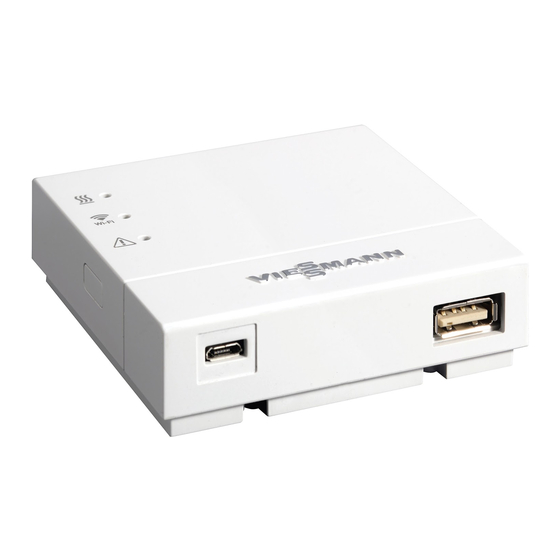
Installation sequence Installation location (cont.) Range reduction: WLAN signals are isolated by service ducts and lift ■ ■ On their way between transmitter and receiver, shafts. WLAN signals are damped, e.g. by air or when pen- ■ WLAN signals suffer interference from appliances etrating walls. - Page 12 For connecting lead Optolink/USB Micro USB for power supply from plug-in power supply unit For connecting lead Optolink/USB 1. Connect the Vitoconnect 100 to the heat source using the Optolink/USB connecting lead. Cable routing in the heat source: Heat source documentation 2.
-
Page 13: Display And Controls
Interpreting the LED indicators Communication with the heat source – Flashes yellow. Connection between Vitoconnect 100 and heat source being established Illuminates green. Connection between Vitoconnect 100 and heat source successfully established Flashes red. No connection to the heat source, see page 16. -
Page 14: Checking The Network Settings
LED , All are illuminated white. The Vitoconnect 100 starts. All are illuminated yellow. The Vitoconnect 100 has been reset to the factory setting and can be commissioned again. Note Flashing: LED 0.5 s on and 0.5 s off Pulsating: LED 0.1 s on and 0.9 s off... - Page 15 7. Follow the instructions in the app. Set up the home network. ■ Enter the system name and location. ■ ■ Accept the data protection agreement and terms of use. The Vitoconnect 100 and the Vitotrol Plus app are set up.
- Page 16 Take care not to damage the Vitoconnect 100. Never disconnect the Vitoconnect 100 from the power supply during firmware installation. Faults without LED indicator Fault Steps All indicators on the Check the power supply and plug-in power supply unit of the Vitoconnect 100. Vitoconnect 100 are off.
-
Page 17: Maintenance Mode
3 LEDs are flashing yellow. 2. Release the reset button. 3. Press the reset button again, this time for longer than 5 s, until all LEDs are illuminated yellow. 4. Release the reset button. The Vitoconnect 100 is back to its factory setting. - Page 18 Troubleshooting Restoring the factory setting (cont.)
-
Page 19: Ordering Parts
Parts lists Ordering parts The following details are required when ordering parts: ■ Order no. (see type plate ■ Position number of the part (from this parts list) Fig. 7... - Page 20 Parts lists EU: Parts list 0001 0002 Fig. 8...
- Page 21 Parts lists EU: Parts list (cont.) Pos. Part 0001 Connecting lead USB/Optolink 0002 Plug-in power supply unit...
- Page 22 Parts lists GB/US/CA: Parts list 0001 0002 Fig. 9...
- Page 23 Parts lists GB/US/CA: Parts list (cont.) Pos. Part 0001 Connecting lead USB/Optolink 0002 Power supply unit with adaptor...
- Page 24 Specification Specification Vitoconnect 100 Rated voltage ― WLAN frequency 2.4 GHz WLAN encryption Unencrypted or WPA2 Internet protocol IPv4 IP allocation DHCP Rated current Power consumption Protection class IP rating IP 30 to EN 60529; ensure through design/installation. Permissible ambient temperature Operation 5 to +40 °C...
- Page 25 Keyword index Keyword index Ambient temperature..........11 Network................ 8 Network operator............5 Network setting Commissioning.............13, 14 – Resetting..............17 Control device Network settings............14 – For ViCare app............7 – For Vitotrol Plus app..........8 Controls..............13 Operating system............. 7, 8 Control units Operation..............8 –...
- Page 28 Applicability Part no. 7571381 7637691 Viessmann Werke GmbH & Co. KG Viessmann Limited D-35107 Allendorf Hortonwood 30, Telford Telephone: +49 6452 70-0 Shropshire, TF1 7YP, GB Fax: +49 6452 70-2780 Telephone: +44 1952 675000 www.viessmann.com Fax: +44 1952 675040 E-mail: info-uk@viessmann.com...